lock VAUXHALL ADAM 2014.5 Service Manual
[x] Cancel search | Manufacturer: VAUXHALL, Model Year: 2014.5, Model line: ADAM, Model: VAUXHALL ADAM 2014.5Pages: 217, PDF Size: 6.68 MB
Page 150 of 217

148Driving and operating
ACME Adapter: Screw the nut of the
filling nozzle onto the adapter. Press
locking lever on filler nozzle down.
DISH (Italy) filler neck: Place the filler
nozzle into the adapter. Press locking lever on filler nozzle down.
Bayonet filler neck: Place filler nozzle
on the adapter and turn to the left or
right through one quarter turn. Pull
locking lever of filler nozzle fully.
EURO filler neck: Press the filler
nozzle onto the adapter until it
engages.
Press the button of the liquid gas supply point. The filling system stops
or begins to run slowly when 80% of
the tank volume is reached
(maximum fill level).
Release button on filling system and
the filling process stops. Release the
locking lever and remove the filler
nozzle. A small quantity of liquid gas
can escape.
Remove adapter and stow in vehicle.
Fit protective cap to prevent the
penetration of foreign bodies into the
filler opening and the system.9 Warning
Due to the system design, an
escape of liquid gas after
releasing the locking lever is
unavoidable. Avoid inhaling.
9 Warning
The liquid gas tank may only be
filled to 80% for safety reasons.
The multivalve on the liquid gas tank
automatically limits the fill quantity. If
a larger quantity is added, we
recommend not exposing the vehicle
to the sun until the excess amount
has been used up.
Filling adapter
As filling systems are not
standardised, different adapters are
required which are available from
Vauxhall Distributors and from
Vauxhall Authorised Repairers.ACME adapter: Belgium, Germany,
Ireland, Luxembourg, Switzerland
Bayonet adapter: Netherlands,
Norway, Spain, United Kingdom
Page 153 of 217
Vehicle care151
■ Open the bonnet, close all doorsand lock the vehicle.
■ Disconnect the clamp from the negative terminal of the vehicle
battery. Beware that all systems are
not functional, e.g. anti-theft alarm
system.
Putting back into operation
When the vehicle is to be put back into
operation:
■ Connect the clamp to the negative terminal of the vehicle battery.
Activate the electronics of the
power windows.
■ Check tyre pressure.
■ Fill up the washer fluid reservoir.
■ Check the engine oil level.
■ Check the coolant level.
■ Fit the number plate if necessary.End-of-life vehicle
recovery
Information on end-of-life vehicle
recovery centres and the recycling of
end-of-life vehicles is available on our website. Only entrust this work to an
authorised recycling centre.
Gas vehicles must be recycled by a
service centre authorised for gas
vehicles.Vehicle checks
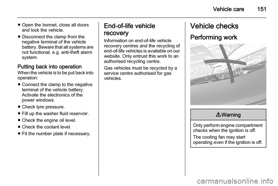
Performing work9 Warning
Only perform engine compartment
checks when the ignition is off.
The cooling fan may start
operating even if the ignition is off.
Page 160 of 217
158Vehicle care
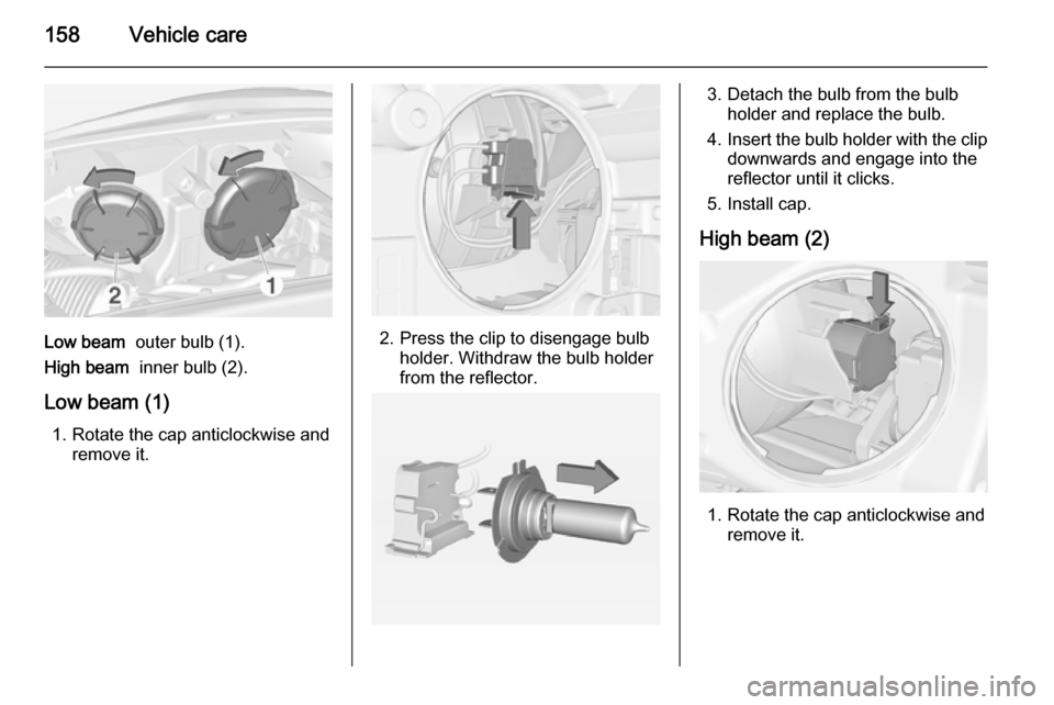
Low beam outer bulb (1).
High beam inner bulb (2).
Low beam (1) 1. Rotate the cap anticlockwise and remove it.2. Press the clip to disengage bulbholder. Withdraw the bulb holder
from the reflector.
3. Detach the bulb from the bulb holder and replace the bulb.
4. Insert the bulb holder with the clip
downwards and engage into the
reflector until it clicks.
5. Install cap.
High beam (2)
1. Rotate the cap anticlockwise and remove it.
Page 161 of 217
Vehicle care159
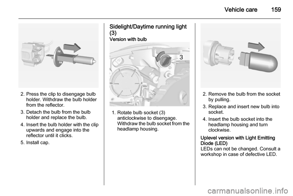
2. Press the clip to disengage bulbholder. Withdraw the bulb holder
from the reflector.
3. Detach the bulb from the bulb holder and replace the bulb.
4. Insert the bulb holder with the clip
upwards and engage into the
reflector until it clicks.
5. Install cap.
Sidelight/Daytime running light
(3)Version with bulb
1. Rotate bulb socket (3) anticlockwise to disengage.
Withdraw the bulb socket from the
headlamp housing.2. Remove the bulb from the socket by pulling.
3. Replace and insert new bulb into socket.
4. Insert the bulb socket into the headlamp housing and turn
clockwise.
Uplevel version with Light Emitting
Diode (LED)
LEDs can not be changed. Consult a
workshop in case of defective LED.
Page 162 of 217
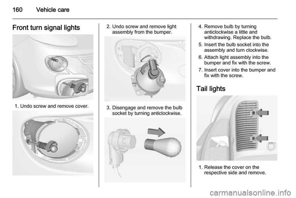
160Vehicle careFront turn signal lights
1. Undo screw and remove cover.
2. Undo screw and remove lightassembly from the bumper.
3. Disengage and remove the bulbsocket by turning anticlockwise.
4. Remove bulb by turninganticlockwise a little and
withdrawing. Replace the bulb.
5. Insert the bulb socket into the assembly and turn clockwise.
6. Attach light assembly into the bumper and fix with the screw.
7. Insert cover into the bumper and fix with the screw.
Tail lights
1. Release the cover on the respective side and remove.
Page 163 of 217
Vehicle care161
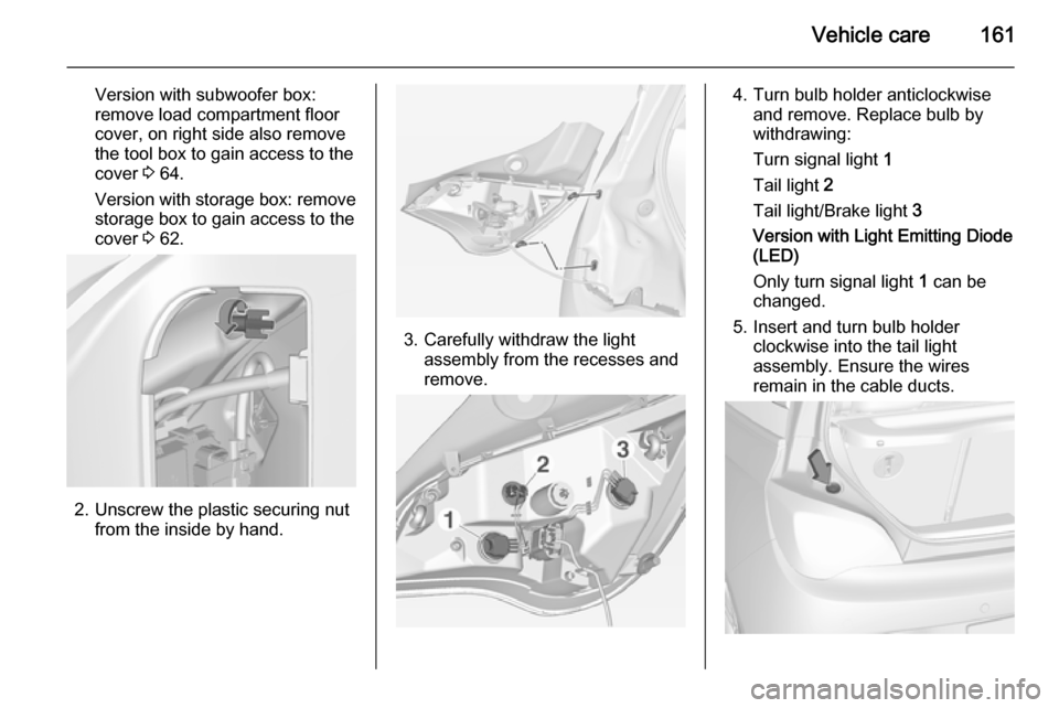
Version with subwoofer box:remove load compartment floor
cover, on right side also remove
the tool box to gain access to the
cover 3 64.
Version with storage box: remove
storage box to gain access to the
cover 3 62.
2. Unscrew the plastic securing nut
from the inside by hand.
3. Carefully withdraw the lightassembly from the recesses and
remove.
4. Turn bulb holder anticlockwise and remove. Replace bulb by
withdrawing:
Turn signal light 1
Tail light 2
Tail light/Brake light 3
Version with Light Emitting Diode (LED)
Only turn signal light 1 can be
changed.
5. Insert and turn bulb holder clockwise into the tail light
assembly. Ensure the wires
remain in the cable ducts.
Page 164 of 217
162Vehicle care
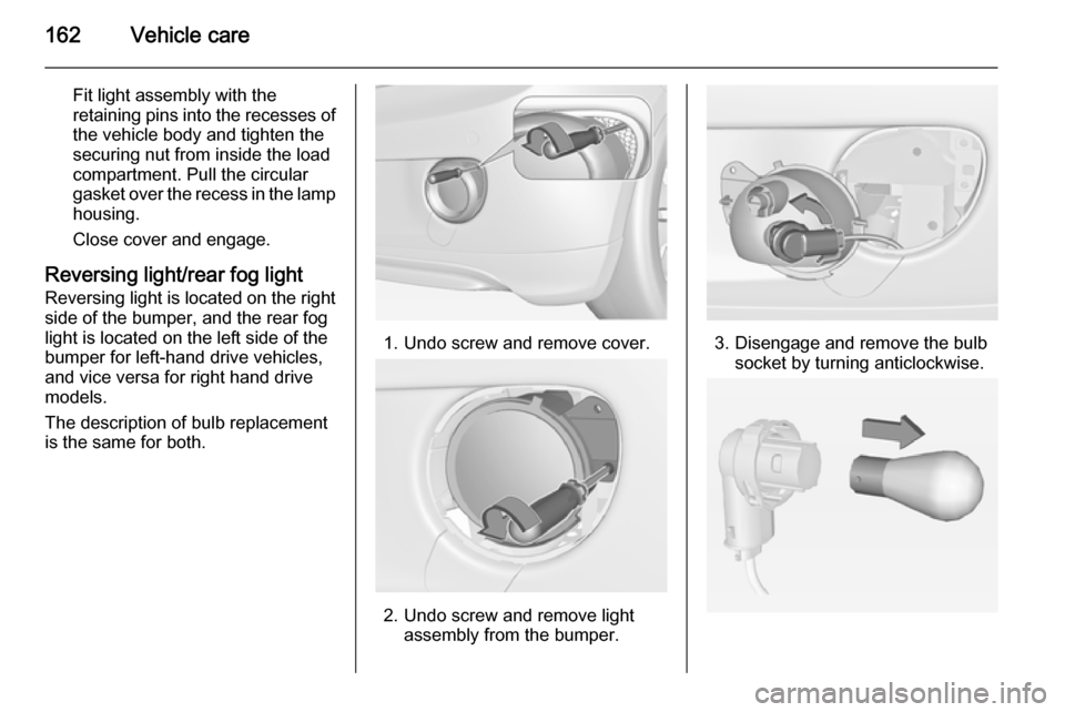
Fit light assembly with the
retaining pins into the recesses of
the vehicle body and tighten the
securing nut from inside the load
compartment. Pull the circular
gasket over the recess in the lamp housing.
Close cover and engage.
Reversing light/rear fog light
Reversing light is located on the right
side of the bumper, and the rear fog
light is located on the left side of the
bumper for left-hand drive vehicles,
and vice versa for right hand drive
models.
The description of bulb replacement
is the same for both.
1. Undo screw and remove cover.
2. Undo screw and remove light assembly from the bumper.
3. Disengage and remove the bulbsocket by turning anticlockwise.
Page 165 of 217

Vehicle care163
4. Remove bulb by turninganticlockwise slightly and
withdrawing. Replace the bulb.
5. Insert the bulb socket into the assembly and turn clockwise.
6. Replace light assembly in the bumper and fix with the screw.
7. Insert cover into the bumper and fix with the screw.
Side turn signal lights To replace bulb, remove lamp
housing:
1. Slide lamp to its left side and remove with its right end.
2. Turn bulb holder anticlockwiseand remove from housing.
3. Pull bulb from bulb holder and replace it.
4. Insert bulb holder and turnclockwise.
5. Insert left end of the lamp, slide to
the left and insert right end.
Number plate light
1. Insert screwdriver in recess of the
cover, press to the side and
release spring.
Page 166 of 217
164Vehicle care
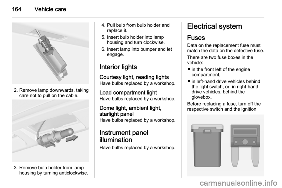
2. Remove lamp downwards, takingcare not to pull on the cable.
3. Remove bulb holder from lamphousing by turning anticlockwise.
4. Pull bulb from bulb holder andreplace it.
5. Insert bulb holder into lamp housing and turn clockwise.
6. Insert lamp into bumper and let engage.
Interior lights Courtesy light, reading lights
Have bulbs replaced by a workshop.
Load compartment light Have bulbs replaced by a workshop.
Dome light, ambient light,starlight panel
Have bulbs replaced by a workshop.
Instrument panel
illumination
Have bulbs replaced by a workshop.Electrical system
Fuses Data on the replacement fuse must
match the data on the defective fuse.
There are two fuse boxes in the
vehicle:
■ in the front left of the engine compartment,
■ in left-hand drive vehicles behind the light switch, or, in right-handdrive vehicles, behind the
glovebox.
Before replacing a fuse, turn off the
respective switch and the ignition.
Page 178 of 217

176Vehicle care
If the wheel covers and tyres used are
not factory approved, the tyres must
not have a rim protection ridge.
Wheel covers must not impair brake
cooling.9 Warning
Use of unsuitable tyres or wheel
covers could lead to sudden
pressure loss and thereby
accidents.
Tyre chains
Tyre chains are only permitted on the
front wheels.
Always use fine mesh chains that add no more than 10 mm to the tyre tread
and the inboard sides (including chain lock).9 Warning
Damage may lead to tyre blowout.
Tyre chains are only permitted on
tyres of size 175/70 R 14,
185/70 R 14, 185/60 R 15,
185/65 R 15 and 195/55 R 16.
Tyre chains are not permitted on tyres of size 215/45 R 17 and 225/35 R 18 .
The use of tyre chains is not permitted
on the temporary spare wheel.
Tyre repair kit
Minor damage to the tyre tread can be
repaired with the tyre repair kit.
Do not remove foreign bodies from
the tyres.
Tyre damage exceeding 4 mm or that
is at tyre's sidewall cannot be repaired with the tyre repair kit.9 Warning
Do not drive faster than 50 mph.
Do not use for a lengthy period.
Steering and handling may be
affected.
If you have a flat tyre:
Apply the parking brake and engage
first gear.