jacking VAUXHALL ADAM 2015.5 Owner's Manual
[x] Cancel search | Manufacturer: VAUXHALL, Model Year: 2015.5, Model line: ADAM, Model: VAUXHALL ADAM 2015.5Pages: 233, PDF Size: 6.98 MB
Page 193 of 233

Vehicle care191
Notice
The driving characteristics of the
repaired tyre are severely affected, therefore have this tyre replaced.
If unusual noise is heard or the
compressor becomes hot, turn
compressor off for at least
30 minutes.
The built-in safety valve opens at a
pressure of 102 psi.
Note the expiry date of the kit. After
this date its sealing capability is no
longer guaranteed. Pay attention to
storage information on sealant
bottle.
Replace the used sealant bottle. Dispose of the bottle as prescribed
by applicable laws.
The compressor and sealant can be used from approx. -30 °C.
The adapters supplied can be used
to pump up other items e.g.
footballs, air mattresses, inflatable
dinghies etc. They are located on the
underside of the compressor. To
remove, screw on compressor air
hose and withdraw adapter.Wheel changing
Make the following preparations and
observe the following information:
■ Park the vehicle on a level, firm and
non-skid surface. The front wheels
must be in the straight-ahead
position.
■ Apply the parking brake and engage first gear or reverse gear.
■ Never change more than one wheel
at once.
■ Use the jack only to change wheels
in case of puncture, not for
seasonal winter or summer tyre
change.
■ The jack is maintenance-free.
■ If the ground on which the vehicle is standing is soft, a solid board
(max. 1 cm thick) should be placed
under the jack.
■ Take heavy objects out of the vehicle before jacking up.
■ No people or animals may be in the
vehicle when it is jacked-up.
■ Never crawl under a jacked-up vehicle.■ Do not start the vehicle when it israised on the jack.
■ Before screwing in the wheel bolts,
clean them and lightly coat the
taper of each wheel bolt with
commercially available grease.9 Warning
Do not grease the thread of the
wheel bolt.
1. Steel wheels:
Pull off the wheel cover.
Alloy wheels with bolt caps Disengage wheel bolt caps with a
screwdriver and remove. To
protect the wheel, place a soft
cloth between the screwdriver
and the alloy wheel.
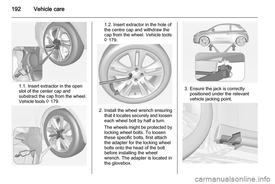
Alloy wheels with centre cap
Two versions are available:
Page 194 of 233

192Vehicle care
1.1. Insert extractor in the open
slot of the center cap and
substract the cap from the wheel.
Vehicle tools 3 179.
1.2. Insert extractor in the hole of
the centre cap and withdraw the
cap from the wheel. Vehicle tools 3 179.
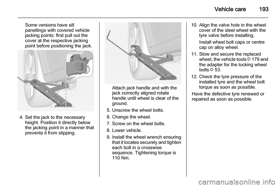
2. Install the wheel wrench ensuring
that it locates securely and loosen
each wheel bolt by half a turn.
The wheels might be protected by
locking wheel bolts. To loosen
these specific bolts, first attach
the adapter for the locking wheel
bolts onto the head of the bolt
before installing the wheel
wrench. The adapter is located in
the glovebox.
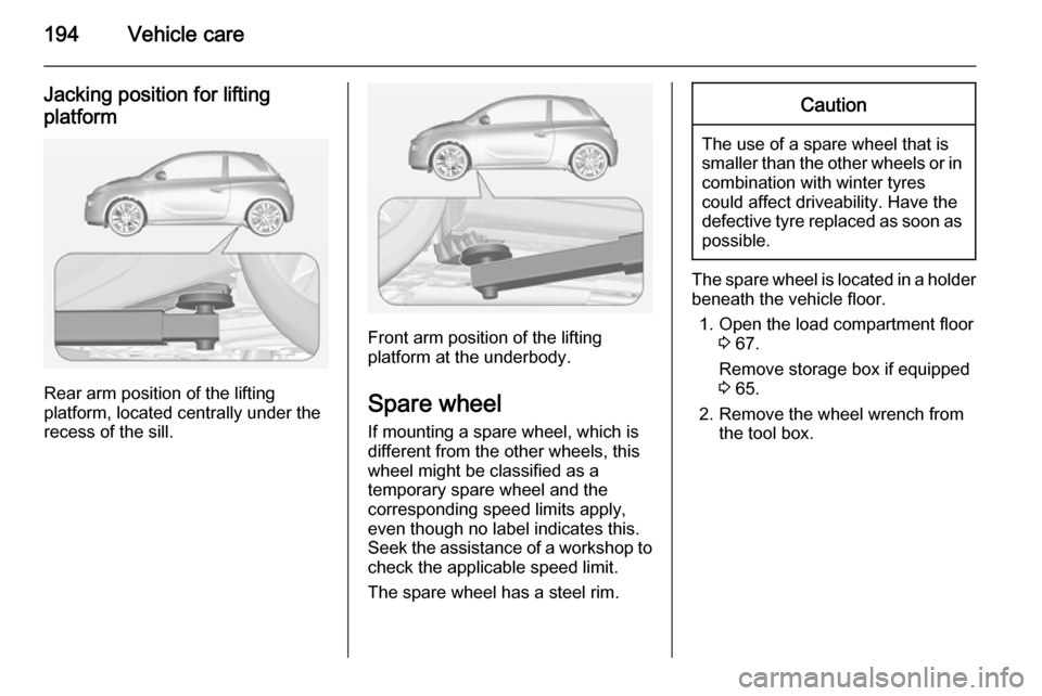
3. Ensure the jack is correctly positioned under the relevant
vehicle jacking point.
Page 195 of 233

Vehicle care193
Some versions have sill
panellings with covered vehicle
jacking points: first pull out the
cover at the respective jacking
point before positioning the jack.
4. Set the jack to the necessary height. Position it directly below
the jacking point in a manner that
prevents it from slipping.
Attach jack handle and with the
jack correctly aligned rotate handle until wheel is clear of theground.
5. Unscrew the wheel bolts.
6. Change the wheel.
7. Screw on the wheel bolts.
8. Lower vehicle.
9. Install the wheel wrench ensuring that it locates securely and tighten
each bolt in a crosswise
sequence. Tightening torque is
110 Nm.
10. Align the valve hole in the wheel cover of the steel wheel with the
tyre valve before installing.
Install wheel bolt caps or centre
cap on alloy wheel.
11. Stow and secure the replaced wheel, the vehicle tools 3 179 and
the adapter for the locking wheel
bolts 3 53.
12. Check the tyre pressure of the installed tyre and the wheel bolt
torque as soon as possible.
Have the defective tyre renewed or
repaired as soon as possible.
Page 196 of 233

194Vehicle care
Jacking position for liftingplatform
Rear arm position of the lifting
platform, located centrally under the
recess of the sill.
Front arm position of the lifting platform at the underbody.
Spare wheel If mounting a spare wheel, which is
different from the other wheels, this
wheel might be classified as a
temporary spare wheel and the
corresponding speed limits apply,
even though no label indicates this.
Seek the assistance of a workshop to
check the applicable speed limit.
The spare wheel has a steel rim.
Caution
The use of a spare wheel that is smaller than the other wheels or in combination with winter tyres
could affect driveability. Have the defective tyre replaced as soon as
possible.
The spare wheel is located in a holder
beneath the vehicle floor.
1. Open the load compartment floor 3 67.
Remove storage box if equipped
3 65.
2. Remove the wheel wrench from the tool box.
Page 224 of 233

222Customer informationCustomer informationCustomer information................222
Vehicle data recording and pri‐ vacy ........................................... 223Customer information
Declaration of conformity Transmission systems
This vehicle has systems that
transmit and/or receive radio waves
subject to Directive 1999/5/EC.
These systems are in compliance with the essential requirements and
other relevant provisions of Directive
1999/5/EC. Copies of the original
Declarations of Conformity can be
obtained on our website.
Jack
Translation of the original declaration
of conformity
Declaration of conformity according
to EC Directive 2006/42/EC
We declare that the product:
Product designation: Jack
Type/GM part number: 13331922 is in compliance with the provisions of
Directive 2006/42/EC.Applied technical standards:GMN9737=JackingGM 14337=Standard
Equipment Jack –
Hardware TestsGMN5127=Vehicle Integrity –
Hoisting and
Service Station
JackingGMW15005=Standard
Equipment Jack
and Spare Tyre,
Vehicle TestISO TS 16949=Quality
management
systems
The signatory is authorised to
compile the technical documentation.
Rüsselsheim, 31st January 2014
signed by
Hans-Peter Metzger
Engineering Group Manager Chassis
& Structure
Adam Opel AG
D-65423 Rüsselsheim