tow VAUXHALL ADAM 2015 User Guide
[x] Cancel search | Manufacturer: VAUXHALL, Model Year: 2015, Model line: ADAM, Model: VAUXHALL ADAM 2015Pages: 225, PDF Size: 6.81 MB
Page 114 of 225
112Climate control
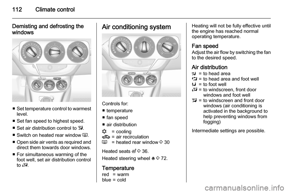
Demisting and defrosting the
windows
■ Set temperature control to warmest
level.
■ Set fan speed to highest speed.
■ Set air distribution control to l.
■ Switch on heated rear window Ü.
■ Open side air vents as required and
direct them towards door windows.
■ For simultaneous warming of the foot well, set air distribution control
to J.
Air conditioning system
Controls for:
■ temperature
■ fan speed
■ air distribution
n=cooling4=air recirculationÜ=heated rear window 3 30
Heated seats ß 3 36.
Heated steering wheel * 3 72.
Temperature
red=warmblue=coldHeating will not be fully effective until
the engine has reached normal
operating temperature.
Fan speed Adjust the air flow by switching the fan
to the desired speed.
Air distributionM=to head areaL=to head area and foot wellK=to foot wellJ=to windscreen, front door
windows and foot welll=to windscreen and front door
windows (air conditioning is
activated in the background to
help preventing windows from
fogging)
Intermediate settings are possible.
Page 116 of 225
114Climate control
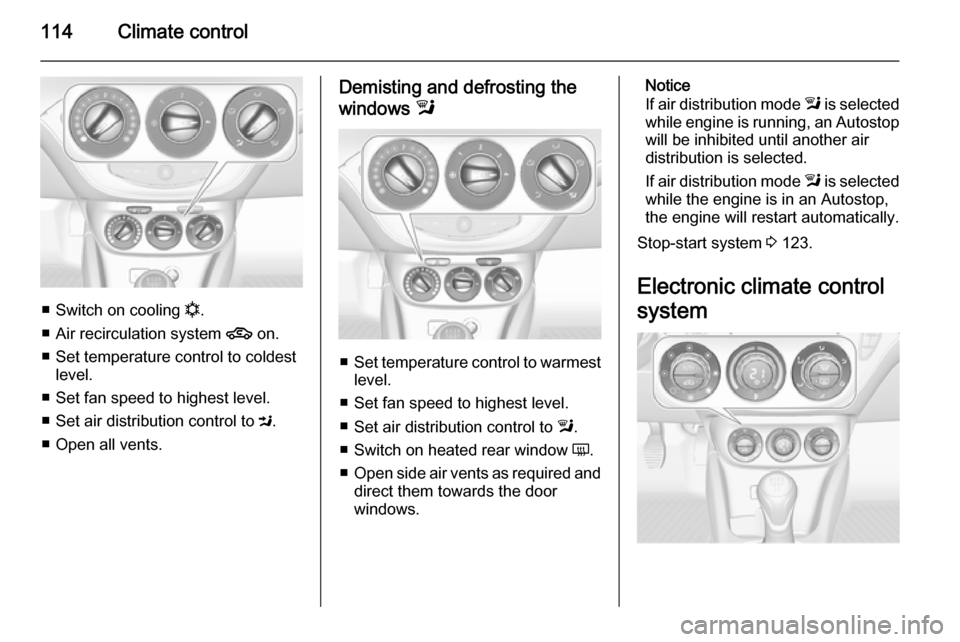
■Switch on cooling n.
■ Air recirculation system 4 on.
■ Set temperature control to coldest level.
■ Set fan speed to highest level.
■ Set air distribution control to M.
■ Open all vents.
Demisting and defrosting the
windows l
■Set temperature control to warmest
level.
■ Set fan speed to highest level.
■ Set air distribution control to l.
■ Switch on heated rear window Ü.
■ Open side air vents as required and
direct them towards the door
windows.
Notice
If air distribution mode l is selected
while engine is running, an Autostop
will be inhibited until another air
distribution is selected.
If air distribution mode l is selected
while the engine is in an Autostop,
the engine will restart automatically.
Stop-start system 3 123.
Electronic climate control
system
Page 127 of 225

Driving and operating125
Restart of the engine by the
stop-start system
The selector lever must be in neutral
to enable an automatic restart.
If one of the following conditions
occurs during an Autostop, the
engine will be restarted automatically by the stop-start system:
■ The stop-start system is manually deactivated.
■ The bonnet is opened.
■ The driver's seat belt is unfastened
and the driver's door is opened.
■ The engine temperature is too low.
■ The charging level of the vehicle battery is below a defined level.
■ The brake vacuum is not sufficient.
■ The vehicle is driven at least at walking speed.
■ The climate control system requests an engine start.
■ The air conditioning is manually switched on.
If the bonnet is not fully closed, a warning message is displayed in the
Driver Information Centre.If an electrical accessory, e.g. a
portable CD player, is connected to
the power outlet, a brief power drop
during restart might be noticeable.
Parking9 Warning
■ Do not park the vehicle on an
easily ignitable surface. The
high temperature of the exhaust
system could ignite the surface.
■ Always apply the parking brake.
Activate the parking brake
without pressing the release
button. Apply as firmly as
possible on a downhill slope or
uphill slope. Depress foot brake
at the same time to reduce
operating force.
■ Switch off the engine.
■ If the vehicle is on a level surface or uphill slope, engage
first gear before removing the ignition key. On an uphill slope,
turn the front wheels away from
the kerb.
If the vehicle is on a downhill
slope, engage reverse gear
before removing the ignition
key. Turn the front wheels
towards the kerb.
■ Close the windows.
■ Remove the ignition key. Turn the steering wheel until the
steering wheel lock is felt to
engage.
■ Lock the vehicle.
■ Activate the anti-theft alarm system.
■ The engine cooling fans may run after the engine has been switchedoff 3 153.
■ After running at high engine speeds
or with high engine loads, operate
the engine briefly at a low load or
run in neutral for
approx. 30 seconds before
switching off, in order to protect the turbocharger.
Page 128 of 225
126Driving and operating
Notice
In the event of an accident with
airbag deployment, the engine is
turned off automatically if the vehicle
comes to a standstill within a certain time.Engine exhaust9 Danger
Engine exhaust gases contain
poisonous carbon monoxide,
which is colourless and odourless and could be fatal if inhaled.
If exhaust gases enter the interior
of the vehicle, open the windows.
Have the cause of the fault
rectified by a workshop.
Avoid driving with an open load
compartment, otherwise exhaust
gases could enter the vehicle.
Catalytic converter
The catalytic converter reduces the
amount of harmful substances in the
exhaust gases.
Caution
Fuel grades other than those listed on pages 3 146, 3 209 could
damage the catalytic converter or
electronic components.
Unburnt petrol will overheat and
damage the catalytic converter.
Therefore avoid excessive use of the starter, running the fuel tank
dry and starting the engine by
pushing or towing.
In the event of misfiring, uneven
engine running, a reduction in engine performance or other unusual
problems, have the cause of the fault
rectified by a workshop as soon as
possible. In an emergency, driving
can be continued for a short period,
keeping vehicle speed and engine
speed low.
Page 129 of 225
Driving and operating127Manual transmission
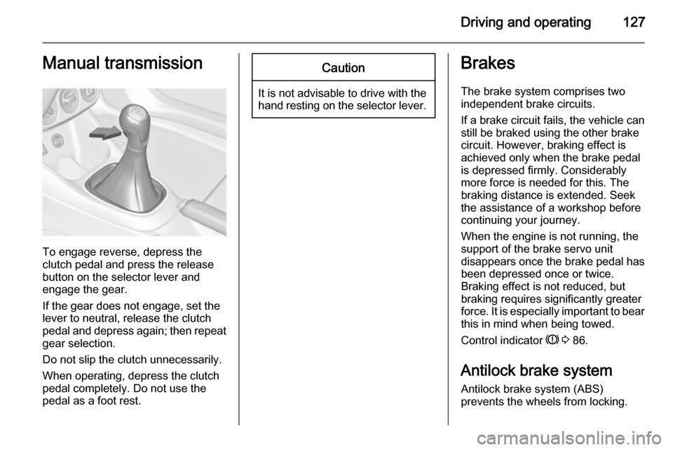
To engage reverse, depress the
clutch pedal and press the release button on the selector lever and
engage the gear.
If the gear does not engage, set the
lever to neutral, release the clutch
pedal and depress again; then repeat
gear selection.
Do not slip the clutch unnecessarily.
When operating, depress the clutch
pedal completely. Do not use the
pedal as a foot rest.
Caution
It is not advisable to drive with the hand resting on the selector lever.
Brakes
The brake system comprises two independent brake circuits.
If a brake circuit fails, the vehicle can
still be braked using the other brake
circuit. However, braking effect is
achieved only when the brake pedal
is depressed firmly. Considerably
more force is needed for this. The
braking distance is extended. Seek the assistance of a workshop before
continuing your journey.
When the engine is not running, the
support of the brake servo unit
disappears once the brake pedal has been depressed once or twice.
Braking effect is not reduced, but
braking requires significantly greater
force. It is especially important to bear
this in mind when being towed.
Control indicator R 3 86.
Antilock brake system
Antilock brake system (ABS)
prevents the wheels from locking.
Page 151 of 225
Driving and operating149
Liquid gas refuellingFollow the operating and safety
instructions of the filling station when
refuelling.
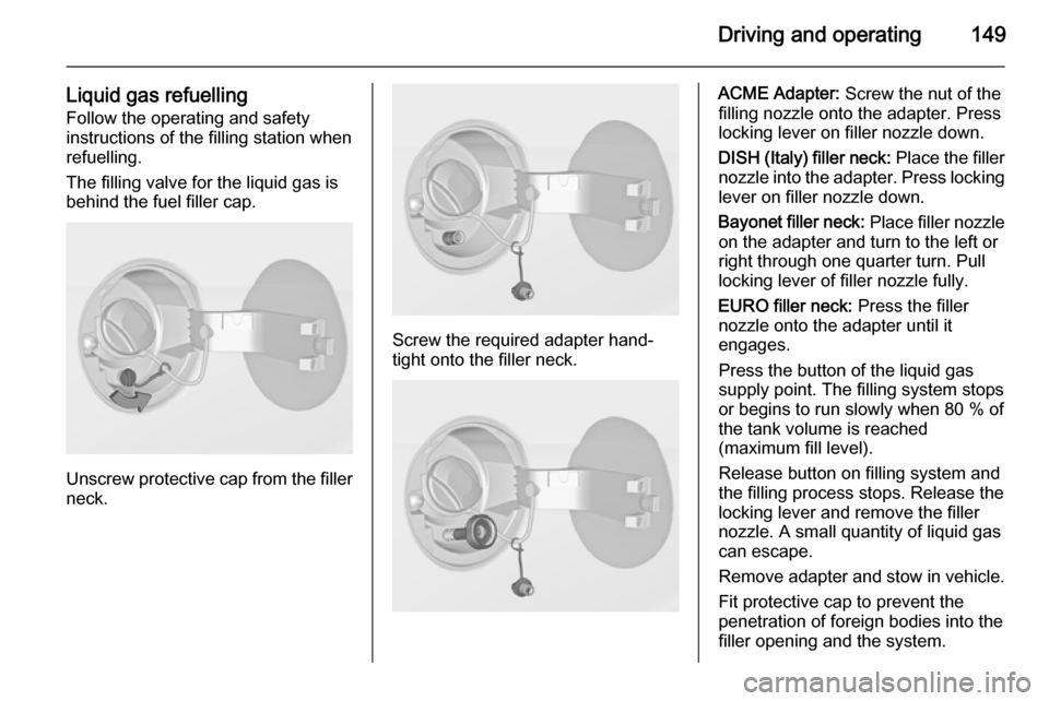
The filling valve for the liquid gas is
behind the fuel filler cap.
Unscrew protective cap from the filler
neck.
Screw the required adapter hand-
tight onto the filler neck.
ACME Adapter: Screw the nut of the
filling nozzle onto the adapter. Press
locking lever on filler nozzle down.
DISH (Italy) filler neck: Place the filler
nozzle into the adapter. Press locking lever on filler nozzle down.
Bayonet filler neck: Place filler nozzle
on the adapter and turn to the left or
right through one quarter turn. Pull
locking lever of filler nozzle fully.
EURO filler neck: Press the filler
nozzle onto the adapter until it
engages.
Press the button of the liquid gas supply point. The filling system stops
or begins to run slowly when 80 % of
the tank volume is reached
(maximum fill level).
Release button on filling system and
the filling process stops. Release the
locking lever and remove the filler
nozzle. A small quantity of liquid gas
can escape.
Remove adapter and stow in vehicle.
Fit protective cap to prevent the
penetration of foreign bodies into the
filler opening and the system.
Page 154 of 225

152Vehicle careVehicle careGeneral Information...................152
Vehicle checks ........................... 153
Bulb replacement .......................159
Electrical system ........................168
Vehicle tools .............................. 173
Wheels and tyres .......................175
Jump starting ............................. 193
Towing ....................................... 194
Appearance care .......................197General Information
Accessories and vehicle
modifications
We recommend the use of genuine parts and accessories and factory
approved parts specific for your
vehicle type. We cannot assess or
guarantee reliability of other products
- even if they have a regulatory or
otherwise granted approval.
Do not make any modifications to the electrical system, e.g. changes of
electronic control units (chip tuning).Caution
When transporting the vehicle on
a train or on a recovery vehicle, the
mud flaps might be damaged.
Vehicle storage
Storage for a long period of time
If the vehicle is to be stored for several months:
■ Wash and wax the vehicle.
■ Have the wax in the engine compartment and underbody
checked.
■ Clean and preserve the rubber seals.
■ Fill up fuel tank completely.
■ Change the engine oil.
■ Drain the washer fluid reservoir.
■ Check the coolant antifreeze and corrosion protection.
■ Adjust tyre pressure to the value specified for full load.
■ Park the vehicle in a dry, well ventilated place. Engage first orreverse gear. Prevent the vehiclefrom rolling.
■ Do not apply the parking brake.
Page 175 of 225

Vehicle care173
No.Circuit35–36–37rear wiper38cigarette lighter39–40–Vehicle toolsTools
Vehicles with tyre repair kit
Some tools and the towing eye are
located together with the tyre repair
kit in a tool box in the load
compartment below the floor cover.
On version with storage box, remove
box first 3 64.
On versions with rear carrier system
or liquid gas engine, the tools are
located together with the towing eye
and tyre repair kit in a suitcase, fixed
with a strap at the left sidewall in the
load compartment.
Page 176 of 225
174Vehicle care
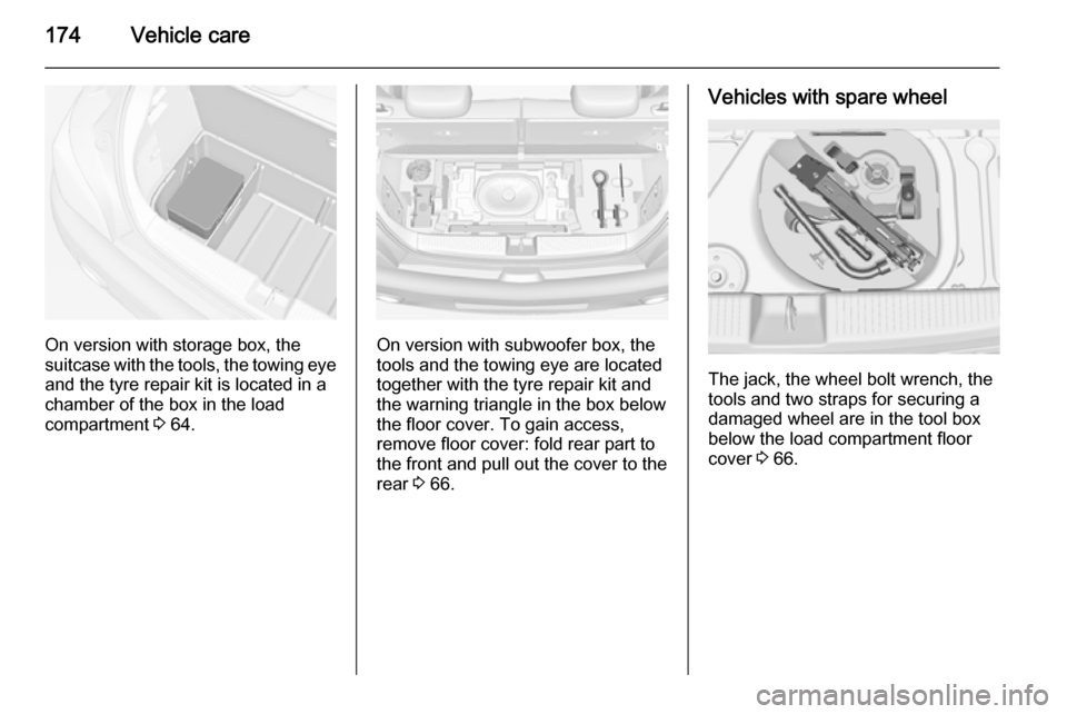
On version with storage box, the
suitcase with the tools, the towing eye
and the tyre repair kit is located in a
chamber of the box in the load
compartment 3 64.On version with subwoofer box, the
tools and the towing eye are located
together with the tyre repair kit and
the warning triangle in the box below
the floor cover. To gain access,
remove floor cover: fold rear part to
the front and pull out the cover to the
rear 3 66.
Vehicles with spare wheel
The jack, the wheel bolt wrench, the
tools and two straps for securing a
damaged wheel are in the tool box below the load compartment floor
cover 3 66.
Page 185 of 225
Vehicle care183
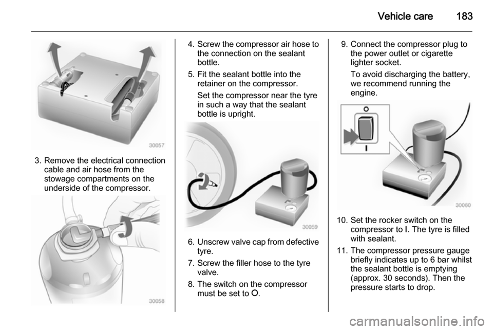
3. Remove the electrical connectioncable and air hose from the
stowage compartments on the
underside of the compressor.
4. Screw the compressor air hose to
the connection on the sealant
bottle.
5. Fit the sealant bottle into the retainer on the compressor.
Set the compressor near the tyre
in such a way that the sealant
bottle is upright.
6. Unscrew valve cap from defective
tyre.
7. Screw the filler hose to the tyre valve.
8. The switch on the compressor must be set to J.
9. Connect the compressor plug to
the power outlet or cigarette
lighter socket.
To avoid discharging the battery,
we recommend running the
engine.
10. Set the rocker switch on the compressor to I. The tyre is filled
with sealant.
11. The compressor pressure gauge briefly indicates up to 6 bar whilstthe sealant bottle is emptying
(approx. 30 seconds). Then the
pressure starts to drop.