warning light VAUXHALL ADAM 2015 Owner's Manual
[x] Cancel search | Manufacturer: VAUXHALL, Model Year: 2015, Model line: ADAM, Model: VAUXHALL ADAM 2015Pages: 225, PDF Size: 6.81 MB
Page 13 of 225

In brief11
1Power windows .....................28
2 Exterior mirrors .....................27
3 Cruise control .....................132
Speed limiter ....................... 134
4 Side air vents ...................... 119
5 Turn and lane-change
signals, headlight flash,
low beam and high beam ....106
Exit lighting ......................... 109
Parking lights ...................... 106
Buttons for Driver
Information Centre ................89
6 Instruments .......................... 79
7 Steering wheel controls .......71
8 Driver Information Centre ...... 89
9 Windscreen wiper,
windscreen washer
system, headlight washer
system, rear wiper, rear
washer system ......................73
10 Central locking system ..........21
City mode ............................ 131
Fuel selector ......................... 80Eco button for stop-start
system ................................. 123
Parking assist ..................... 135
Seat heating .......................... 36
Heated steering wheel ..........72
11 Colour-Info-Display ..............94
Graphic-Info-Display .............95
12 Hazard warning flashers ....105
Control indicator for airbag
deactivation .......................... 85
Control indicator for front
passenger seat belt .............84
13 Anti-theft alarm system
status LED ........................... 25
14 Centre air vents .................. 119
15 Side air vents passenger
side ..................................... 119
16 Glovebox .............................. 52
Fuse box ............................ 171
17 Climate control system ........ 111
18 Power outlet .......................... 78
19 AUX input, USB input ...........1020Selector lever, manual
transmission ....................... 127
21 Parking brake ......................128
22 Ignition switch with
steering wheel lock ............122
23 Horn ..................................... 72
Driver airbag ........................ 42
24 Bonnet release lever ..........154
25 Steering wheel adjustment ..71
26 Light switch ........................ 103
Headlight range
adjustment ......................... 105
Rear fog light ...................... 106
Brightness of instrument
panel illumination ................107
Brightness of ambient light 107
Page 15 of 225

In brief13
Turn and lane-change signalslever up=right turn signallever down=left turn signal
Turn and lane-change signals
3 106, Parking lights 3 106.
Hazard warning flashers
Operated with the ¨ button.
Hazard warning flashers 3 105.
Horn
Press j.
Page 19 of 225
In brief17
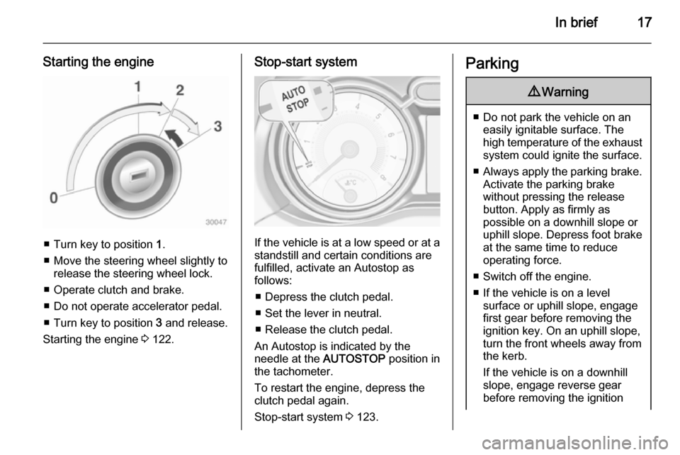
Starting the engine
■ Turn key to position 1.
■ Move the steering wheel slightly to release the steering wheel lock.
■ Operate clutch and brake.
■ Do not operate accelerator pedal.
■ Turn key to position 3 and release.
Starting the engine 3 122.
Stop-start system
If the vehicle is at a low speed or at a
standstill and certain conditions are
fulfilled, activate an Autostop as
follows:
■ Depress the clutch pedal.
■ Set the lever in neutral.
■ Release the clutch pedal.
An Autostop is indicated by the
needle at the AUTOSTOP position in
the tachometer.
To restart the engine, depress the clutch pedal again.
Stop-start system 3 123.
Parking9 Warning
■ Do not park the vehicle on an
easily ignitable surface. The
high temperature of the exhaust system could ignite the surface.
■ Always apply the parking brake.
Activate the parking brake
without pressing the release
button. Apply as firmly as
possible on a downhill slope or
uphill slope. Depress foot brake
at the same time to reduce
operating force.
■ Switch off the engine.
■ If the vehicle is on a level surface or uphill slope, engage
first gear before removing the ignition key. On an uphill slope,
turn the front wheels away from
the kerb.
If the vehicle is on a downhill
slope, engage reverse gear
before removing the ignition
Page 28 of 225

26Keys, doors and windows
Status during the first 30 seconds of
anti-theft alarm system activation:LED illuminates=test, arming delayLED flashes
quickly=doors, tailgate or
bonnet not
completely closed, or system fault
Status after system is armed:
LED flashes
slowly=system is armed
Seek the assistance of a workshop in
the event of faults.
Deactivation
Unlocking the vehicle by pressing
button c deactivates anti-theft alarm
system.
The system is not deactivated by
unlocking the driver's door with the
key or with the central locking button
in the passenger compartment.
Alarm
When triggered, the alarm horn
sounds and the hazard warning lights flash simultaneously. The number
and duration of alarm signals are
stipulated by legislation.
The alarm can be silenced by
pressing any button on the radio remote control or by switching on the
ignition.
The anti-theft alarm system can only
be deactivated by pressing button c
on the radio remote control or by
switching on the ignition.
A triggered alarm, which has not been interrupted by the driver, will be
indicated by the hazard warning
lights. They will flash quickly three
times when the vehicle is unlocked
with the radio remote control.
Vehicle messages 3 96.
Immobiliser The system is part of the ignition
switch and checks whether the
vehicle is allowed to be started with the key being used.The immobiliser is activated
automatically after the key has been removed from the ignition switch.
If the control indicator d flashes when
the ignition is on, there is a fault in the
system; the engine cannot be started. Switch off the ignition and repeat the
start attempt.
If the control indicator continues
flashing, attempt to start the engine
using the spare key and seek the
assistance of a workshop.
Notice
The immobiliser does not lock the
doors. You should always lock the
vehicle after leaving it.
Switch on the anti-theft alarm
system 3 21, 3 25.
Control indicator d 3 88.
Page 30 of 225
28Keys, doors and windowsInterior mirrors
Manual anti-dazzle
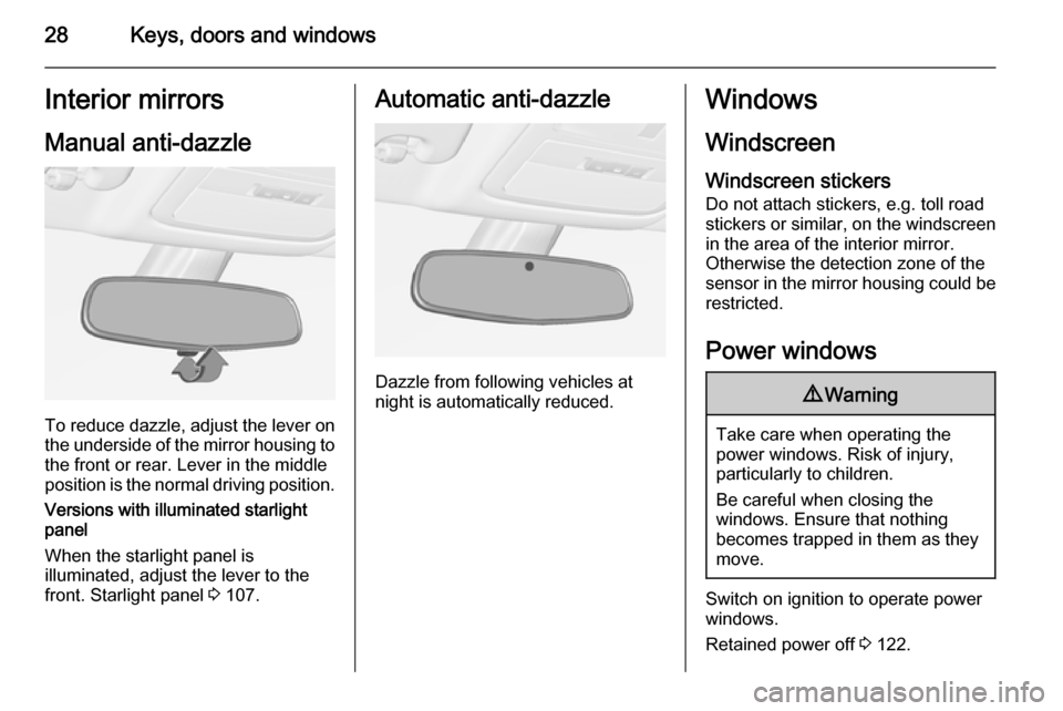
To reduce dazzle, adjust the lever on the underside of the mirror housing to
the front or rear. Lever in the middle
position is the normal driving position.
Versions with illuminated starlight
panel
When the starlight panel is
illuminated, adjust the lever to the
front. Starlight panel 3 107.
Automatic anti-dazzle
Dazzle from following vehicles at
night is automatically reduced.
Windows
Windscreen
Windscreen stickers
Do not attach stickers, e.g. toll road
stickers or similar, on the windscreen in the area of the interior mirror.
Otherwise the detection zone of the
sensor in the mirror housing could be
restricted.
Power windows9 Warning
Take care when operating the
power windows. Risk of injury,
particularly to children.
Be careful when closing the
windows. Ensure that nothing
becomes trapped in them as they
move.
Switch on ignition to operate power
windows.
Retained power off 3 122.
Page 31 of 225
Keys, doors and windows29
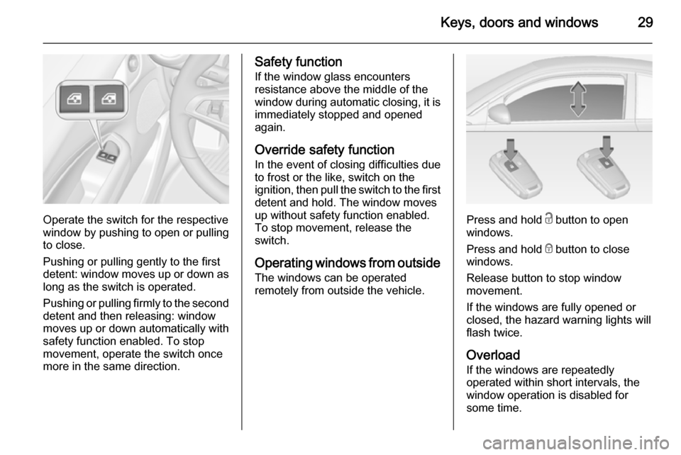
Operate the switch for the respective
window by pushing to open or pulling to close.
Pushing or pulling gently to the first
detent: window moves up or down as long as the switch is operated.
Pushing or pulling firmly to the second
detent and then releasing: window
moves up or down automatically with
safety function enabled. To stop
movement, operate the switch once
more in the same direction.
Safety function
If the window glass encounters
resistance above the middle of the
window during automatic closing, it is
immediately stopped and opened again.
Override safety function
In the event of closing difficulties due
to frost or the like, switch on the
ignition, then pull the switch to the first
detent and hold. The window moves
up without safety function enabled.
To stop movement, release the
switch.
Operating windows from outside
The windows can be operated
remotely from outside the vehicle.
Press and hold c button to open
windows.
Press and hold e button to close
windows.
Release button to stop window
movement.
If the windows are fully opened or
closed, the hazard warning lights will
flash twice.
Overload
If the windows are repeatedly
operated within short intervals, the
window operation is disabled for
some time.
Page 35 of 225
Seats, restraints33
Rear head restraints, heightadjustment
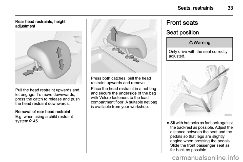
Pull the head restraint upwards and
let engage. To move downwards, press the catch to release and push
the head restraint downwards.
Removal of rear head restraint
E.g. when using a child restraint
system 3 45.
Press both catches, pull the head
restraint upwards and remove.
Place the head restraint in a net bag
and secure the underside of the bag
with Velcro fasteners to the load
compartment floor. A suitable net bag
is available from your workshop.
Front seats
Seat position9 Warning
Only drive with the seat correctly
adjusted.
■ Sit with buttocks as far back against
the backrest as possible. Adjust the distance between the seat and the
pedals so that legs are slightly
angled when pressing the pedals.
Slide the front passenger seat as
far back as possible.
Page 36 of 225
34Seats, restraints
■ Sit with shoulders as far backagainst the backrest as possible.Set the backrest rake so that it is
possible to easily reach the
steering wheel with arms slightly
bent. Maintain contact between
shoulders and the backrest when
turning the steering wheel. Do not
angle the backrest too far back. We recommend a maximum rake ofapprox. 25°.
■ Adjust the steering wheel 3 71.
■ Set seat height high enough to have a clear field of vision on allsides and of all display instruments.
There should be at least one hand
of clearance between head and the
roof frame. Your thighs should rest
lightly on the seat without pressing
into it.
■ Adjust the head restraint 3 32.Seat adjustment9 Danger
Do not sit nearer than 25 cm from
the steering wheel, to permit safe
airbag deployment.
9 Warning
Never adjust seats while driving as
they could move uncontrollably.
9 Warning
Never store any objects under the
seats.
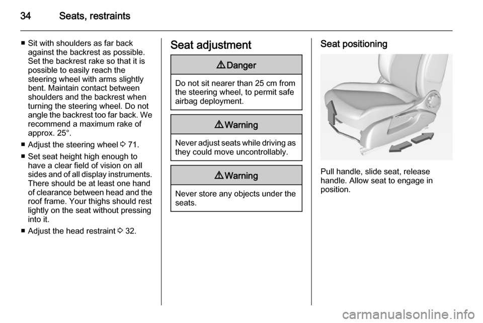
Seat positioning
Pull handle, slide seat, release
handle. Allow seat to engage in
position.
Page 45 of 225
Seats, restraints43
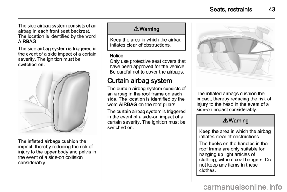
The side airbag system consists of an
airbag in each front seat backrest.
The location is identified by the word
AIRBAG .
The side airbag system is triggered in the event of a side impact of a certain
severity. The ignition must be
switched on.
The inflated airbags cushion the
impact, thereby reducing the risk of
injury to the upper body and pelvis in
the event of a side-on collision
considerably.
9 Warning
Keep the area in which the airbag
inflates clear of obstructions.
Notice
Only use protective seat covers that have been approved for the vehicle.Be careful not to cover the airbags.
Curtain airbag system
The curtain airbag system consists of an airbag in the roof frame on each
side. The location is identified by the
word AIRBAG on the roof pillars.
The curtain airbag system is triggered
in the event of a side-on impact of a
certain severity. The ignition must be
switched on.
The inflated airbags cushion the
impact, thereby reducing the risk of
injury to the head in the event of a
side-on impact considerably.
9 Warning
Keep the area in which the airbag
inflates clear of obstructions.
The hooks on the handles in the
roof frame are only suitable for
hanging up light articles of
clothing, without coat hangers. Do not keep any items in these
clothes.
Page 57 of 225

Storage55
Pull release lever up. The system
disengages and travels quickly out of
the bumper.
Completely pull out the rear carrier
system until you hear it engage.
Ensure that it is not possible to push in the rear carrier system without
pulling the release lever again.
9 Warning
It is only permissible to fit objects
to the rear carrier system if the
system has been correctly
engaged. If the rear carrier system
will not engage correctly, do not fit
objects to the system and slide the system back. Seek the assistance
of a workshop.
Unfold number plate light
Lift the number plate light and fold it
backwards.
Fold out tail lamps
Swivel hinges of both tail lamps
backwards as far as it will go.