lock VAUXHALL ADAM 2016.5 Owner's Guide
[x] Cancel search | Manufacturer: VAUXHALL, Model Year: 2016.5, Model line: ADAM, Model: VAUXHALL ADAM 2016.5Pages: 239, PDF Size: 7.2 MB
Page 57 of 239
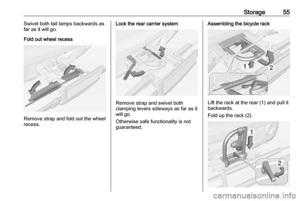
Storage55Swivel both tail lamps backwards as
far as it will go.
Fold out wheel recess
Remove strap and fold out the wheel
recess.
Lock the rear carrier system
Remove strap and swivel both
clamping levers sideways as far as it
will go.
Otherwise safe functionality is not
guaranteed.
Assembling the bicycle rack
Lift the rack at the rear (1) and pull it
backwards.
Fold up the rack (2).
Page 59 of 239
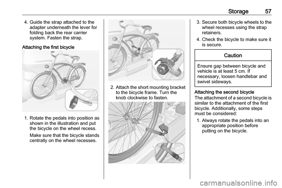
Storage574. Guide the strap attached to theadapter underneath the lever for
folding back the rear carrier
system. Fasten the strap.
Attaching the first bicycle
1. Rotate the pedals into position as shown in the illustration and put
the bicycle on the wheel recess.
Make sure that the bicycle stands centrally on the wheel recesses.
2. Attach the short mounting bracket
to the bicycle frame. Turn the
knob clockwise to fasten.
3. Secure both bicycle wheels to the
wheel recesses using the strap
retainers.
4. Check the bicycle to make sure it is secure.Caution
Ensure gap between bicycle and
vehicle is at least 5 cm. If
necessary, loosen handlebar and swivel sideways.
Attaching the second bicycle
The attachment of a second bicycle is
similar to the attachment of the first
bicycle. Additionally, some steps
must be considered:
1. Always rotate the pedals into an appropriate position before
putting on the bicycle.
Page 61 of 239
Storage59
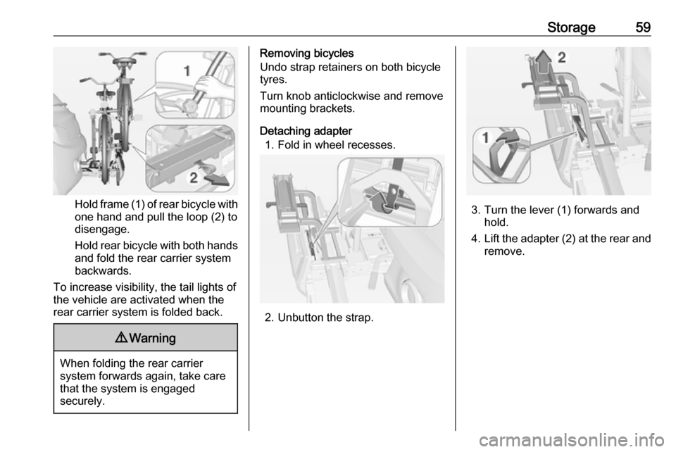
Hold frame (1) of rear bicycle with
one hand and pull the loop (2) to
disengage.
Hold rear bicycle with both hands and fold the rear carrier system
backwards.
To increase visibility, the tail lights of
the vehicle are activated when the
rear carrier system is folded back.
9 Warning
When folding the rear carrier
system forwards again, take care
that the system is engaged
securely.
Removing bicycles
Undo strap retainers on both bicycle
tyres.
Turn knob anticlockwise and remove
mounting brackets.
Detaching adapter 1. Fold in wheel recesses.
2. Unbutton the strap.
3. Turn the lever (1) forwards and hold.
4. Lift the adapter (2) at the rear and
remove.
Page 63 of 239
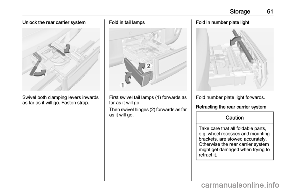
Storage61Unlock the rear carrier system
Swivel both clamping levers inwards
as far as it will go. Fasten strap.
Fold in tail lamps
First swivel tail lamps (1) forwards as
far as it will go.
Then swivel hinges (2) forwards as far as it will go.
Fold in number plate light
Fold number plate light forwards.
Retracting the rear carrier system
Caution
Take care that all foldable parts,
e.g. wheel recesses and mounting brackets, are stowed accurately.
Otherwise the rear carrier system might get damaged when trying to retract it.
Page 64 of 239
62Storage
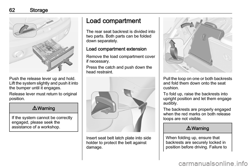
Push the release lever up and hold.
Lift the system slightly and push it into the bumper until it engages.
Release lever must return to original
position.
9 Warning
If the system cannot be correctly
engaged, please seek the
assistance of a workshop.
Load compartment
The rear seat backrest is divided into
two parts. Both parts can be folded
down separately.
Load compartment extension
Remove the load compartment cover
if necessary.
Press the catch and push down the
head restraint.
Insert seat belt latch plate into side
holder to protect the belt against
damage.
Pull the loop on one or both backrests and fold them down onto the seat
cushion.
To fold up, raise the backrests into
upright position and let them engage
audibly.
The backrests are properly engaged
when the red marks on both release
loops are not visible.
9 Warning
When folding up, ensure that
backrests are securely locked in
position before driving. Failure to
Page 65 of 239
Storage63do so may result in personal injuryor damage to load or vehicle in the
event of heavy braking or collision.
Hook for carrier bags
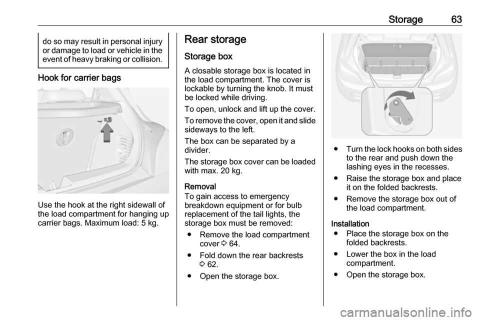
Use the hook at the right sidewall of
the load compartment for hanging up carrier bags. Maximum load: 5 kg.
Rear storage
Storage box A closable storage box is located in
the load compartment. The cover is lockable by turning the knob. It must
be locked while driving.
To open, unlock and lift up the cover.
To remove the cover, open it and slide sideways to the left.
The box can be separated by a
divider.
The storage box cover can be loaded
with max. 20 kg.
Removal
To gain access to emergency breakdown equipment or for bulb
replacement of the tail lights, the
storage box must be removed:
● Remove the load compartment cover 3 64.
● Fold down the rear backrests 3 62.
● Open the storage box.
● Turn the lock hooks on both sides
to the rear and push down the
lashing eyes in the recesses.
● Raise the storage box and place it on the folded backrests.
● Remove the storage box out of the load compartment.
Installation ● Place the storage box on the folded backrests.
● Lower the box in the load compartment.
● Open the storage box.
Page 66 of 239
64Storage● Raise the lashing eyes on bothsides and turn the lock hooks to
the front to fix the box to the
lashing eyes.
● Raise the rear backrests and install the load compartment
cover.
● Stow the suitcase with tyre repair
kit in a chamber of the storage
box.
● Close and lock the cover.
Load compartment cover
Do not place any objects on the cover.
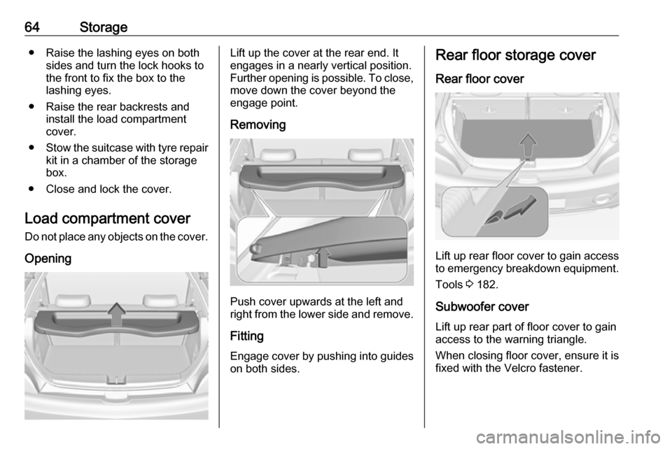
OpeningLift up the cover at the rear end. It
engages in a nearly vertical position.
Further opening is possible. To close, move down the cover beyond the
engage point.
Removing
Push cover upwards at the left and
right from the lower side and remove.
Fitting Engage cover by pushing into guides
on both sides.
Rear floor storage cover
Rear floor cover
Lift up rear floor cover to gain access
to emergency breakdown equipment.
Tools 3 182.
Subwoofer cover
Lift up rear part of floor cover to gain
access to the warning triangle.
When closing floor cover, ensure it is
fixed with the Velcro fastener.
Page 71 of 239

Instruments and controls69Instruments and
controlsControls ....................................... 70
Steering wheel adjustment ........70
Steering wheel controls .............70
Heated steering wheel ...............70
Horn ........................................... 71
Windscreen wiper/washer .........71
Rear window wiper/washer .......73
Outside temperature ..................73
Clock ......................................... 74
Power outlets ............................. 76
Inductive charging .....................76
Cigarette lighter ......................... 77
Ashtrays .................................... 77
Warning lights, gauges and indi‐
cators ........................................... 78
Instrument cluster ......................78
Speedometer ............................. 78
Odometer .................................. 78
Trip odometer ............................ 78
Tachometer ............................... 78
Fuel gauge ................................ 79
Fuel selector .............................. 79
Engine coolant temperature gauge ....................................... 80Service display.......................... 80
Control indicators ......................81
Turn signal ................................. 83
Seat belt reminder .....................83
Airbag and belt tensioners .........84
Airbag deactivation ....................84
Charging system .......................84
Malfunction indicator light ..........85
Service vehicle soon .................85
Brake and clutch system ...........85
Operate pedal ............................ 85
Antilock brake system (ABS) .....86
Upshift ....................................... 86
Power steering .......................... 86
Ultrasonic parking assist ...........86
Electronic Stability Control off ...86
Electronic Stability Control and Traction Control system ...........86
Tyre pressure monitoring system ...................................... 87
Engine oil pressure ....................87
Low fuel ..................................... 87
Immobiliser ................................ 88
Exterior light .............................. 88
High beam ................................. 88
Rear fog light ............................. 88
Cruise control ............................ 88
Door open .................................. 88
Information displays .....................88
Driver Information Centre ..........88Colour-Info-Display ....................93
Graphic-Info-Display ..................94
Vehicle messages ........................95
Warning chimes .........................97
Battery voltage .......................... 97
Vehicle personalisation ................98
OnStar ....................................... 101
Page 72 of 239
70Instruments and controlsControlsSteering wheel adjustment
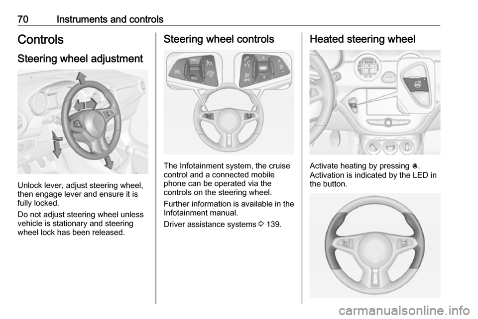
Unlock lever, adjust steering wheel,
then engage lever and ensure it is
fully locked.
Do not adjust steering wheel unless
vehicle is stationary and steering
wheel lock has been released.
Steering wheel controls
The Infotainment system, the cruise
control and a connected mobile
phone can be operated via the
controls on the steering wheel.
Further information is available in the
Infotainment manual.
Driver assistance systems 3 139.
Heated steering wheel
Activate heating by pressing *.
Activation is indicated by the LED in
the button.
Page 76 of 239
74Instruments and controls
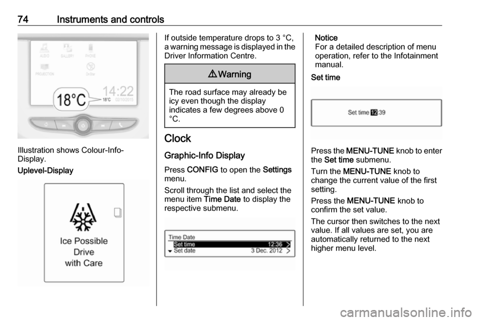
Illustration shows Colour-Info-
Display.
Uplevel-Display
If outside temperature drops to 3 °C,
a warning message is displayed in the Driver Information Centre.9 Warning
The road surface may already be
icy even though the display
indicates a few degrees above 0
°C.
Clock
Graphic-Info Display
Press CONFIG to open the Settings
menu.
Scroll through the list and select the
menu item Time Date to display the
respective submenu.
Notice
For a detailed description of menu
operation, refer to the Infotainment
manual.
Set time
Press the MENU-TUNE knob to enter
the Set time submenu.
Turn the MENU-TUNE knob to
change the current value of the first setting.
Press the MENU-TUNE knob to
confirm the set value.
The cursor then switches to the next
value. If all values are set, you are
automatically returned to the next
higher menu level.