lock VAUXHALL ADAM 2016.5 Repair Manual
[x] Cancel search | Manufacturer: VAUXHALL, Model Year: 2016.5, Model line: ADAM, Model: VAUXHALL ADAM 2016.5Pages: 239, PDF Size: 7.2 MB
Page 176 of 239
174Vehicle care
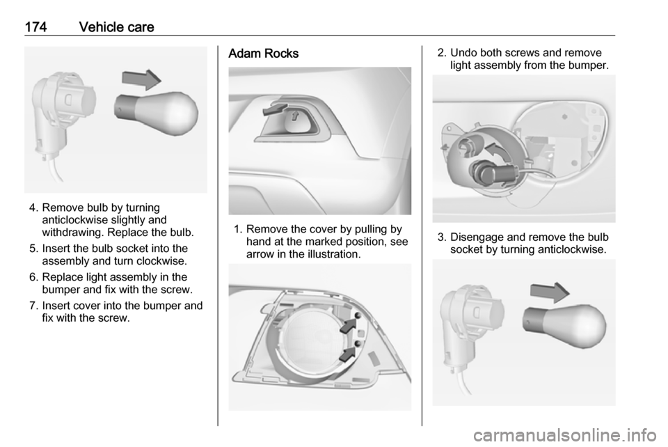
4. Remove bulb by turninganticlockwise slightly and
withdrawing. Replace the bulb.
5. Insert the bulb socket into the assembly and turn clockwise.
6. Replace light assembly in the bumper and fix with the screw.
7. Insert cover into the bumper and fix with the screw.
Adam Rocks
1. Remove the cover by pulling by hand at the marked position, see
arrow in the illustration.
2. Undo both screws and remove light assembly from the bumper.
3. Disengage and remove the bulb socket by turning anticlockwise.
Page 177 of 239
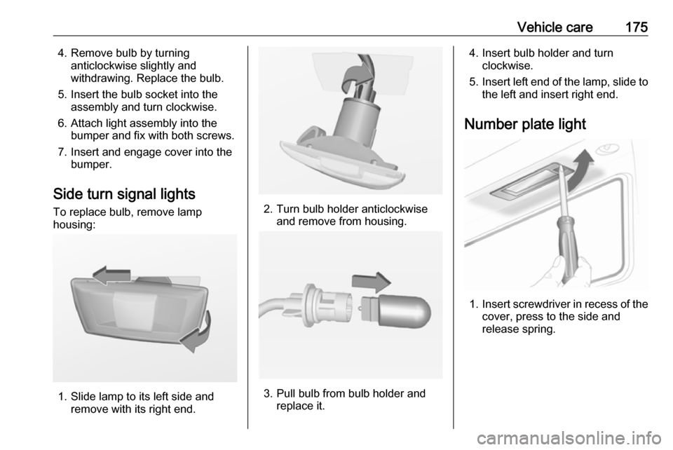
Vehicle care1754. Remove bulb by turninganticlockwise slightly and
withdrawing. Replace the bulb.
5. Insert the bulb socket into the assembly and turn clockwise.
6. Attach light assembly into the bumper and fix with both screws.
7. Insert and engage cover into the bumper.
Side turn signal lights
To replace bulb, remove lamp
housing:
1. Slide lamp to its left side and remove with its right end.
2. Turn bulb holder anticlockwiseand remove from housing.
3. Pull bulb from bulb holder and replace it.
4. Insert bulb holder and turnclockwise.
5. Insert left end of the lamp, slide to
the left and insert right end.
Number plate light
1. Insert screwdriver in recess of the
cover, press to the side and
release spring.
Page 178 of 239
176Vehicle care
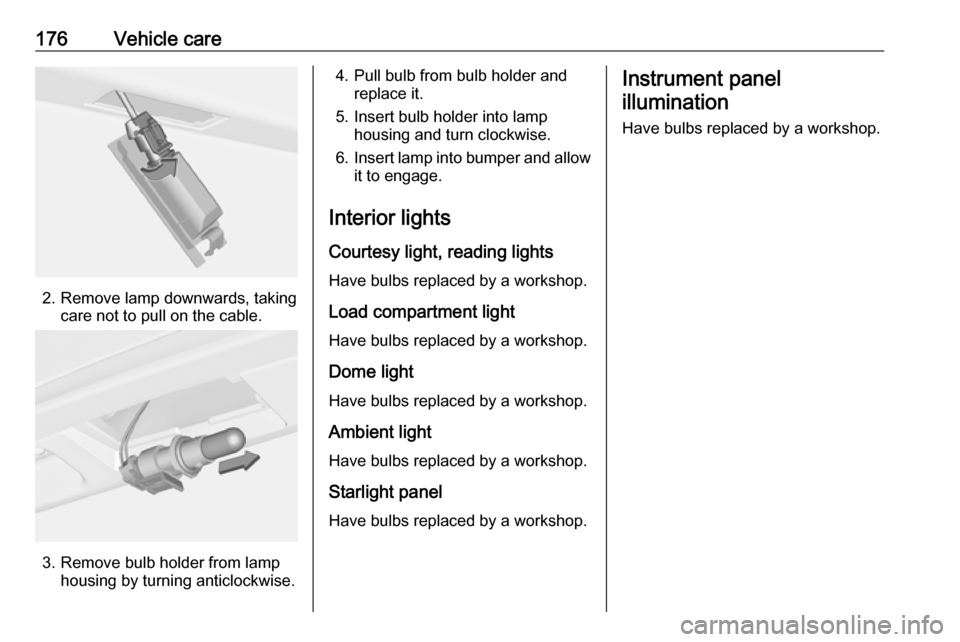
2. Remove lamp downwards, takingcare not to pull on the cable.
3. Remove bulb holder from lamphousing by turning anticlockwise.
4. Pull bulb from bulb holder andreplace it.
5. Insert bulb holder into lamp housing and turn clockwise.
6. Insert lamp into bumper and allow
it to engage.
Interior lights Courtesy light, reading lights
Have bulbs replaced by a workshop.
Load compartment light
Have bulbs replaced by a workshop.
Dome light
Have bulbs replaced by a workshop.
Ambient lightHave bulbs replaced by a workshop.
Starlight panel
Have bulbs replaced by a workshop.Instrument panel illumination
Have bulbs replaced by a workshop.
Page 191 of 239
Vehicle care189indicators (TWI). Their position is
indicated by markings on the
sidewall.
Tyres age, even if they are not used.
We recommend tyre replacement
every 6 years.
Changing tyre and wheel size
If tyres of a different size than those
fitted at the factory are used, it may be necessary to reprogramme the
speedometer as well as the nominal
tyre pressure and to make other
vehicle modifications.
After converting to a different tyre
size, have the label with tyre
pressures replaced.Caution
When converting to wheels with 14'', the ground clearance will be
reduced. This must be considered
when passing over obstacles.
9 Warning
Use of unsuitable tyres or wheels
may lead to accidents and will
invalidate the vehicle type
approval.
Wheel covers
Wheel covers and tyres that are
factory approved for the respective
vehicle and comply with all of the
relevant wheel and tyre combination
requirements must be used.
If the wheel covers and tyres used are
not factory approved, the tyres must
not have a rim protection ridge.
Wheel covers must not impair brake
cooling.
9 Warning
Use of unsuitable tyres or wheel
covers could lead to sudden
pressure loss and thereby
accidents.
Steel wheels: When using locking
wheel bolts, do not attach wheel
covers.
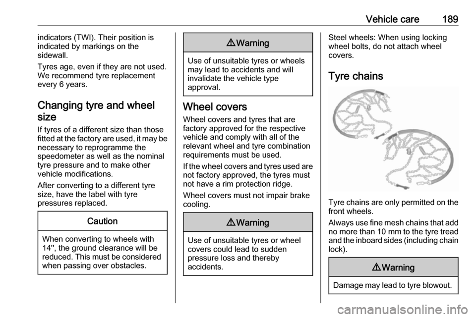
Tyre chains
Tyre chains are only permitted on the
front wheels.
Always use fine mesh chains that add no more than 10 mm to the tyre tread
and the inboard sides (including chain lock).
9 Warning
Damage may lead to tyre blowout.
Page 197 of 239
Vehicle care195cap from the wheel. Vehicle tools
3 182.
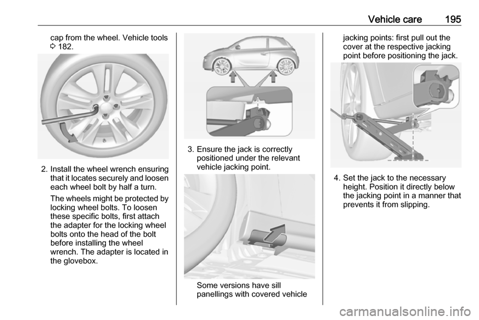
2. Install the wheel wrench ensuring
that it locates securely and loosen
each wheel bolt by half a turn.
The wheels might be protected by
locking wheel bolts. To loosen
these specific bolts, first attach
the adapter for the locking wheel
bolts onto the head of the bolt
before installing the wheel
wrench. The adapter is located in
the glovebox.
3. Ensure the jack is correctly positioned under the relevant
vehicle jacking point.
Some versions have sill
panellings with covered vehicle
jacking points: first pull out the
cover at the respective jacking
point before positioning the jack.
4. Set the jack to the necessary height. Position it directly below
the jacking point in a manner that
prevents it from slipping.
Page 198 of 239
196Vehicle care
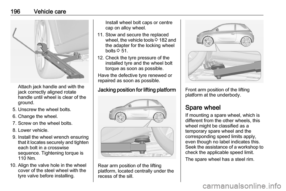
Attach jack handle and with the
jack correctly aligned rotate handle until wheel is clear of theground.
5. Unscrew the wheel bolts.
6. Change the wheel.
7. Screw on the wheel bolts.
8. Lower vehicle.
9. Install the wheel wrench ensuring that it locates securely and tighten
each bolt in a crosswise
sequence. Tightening torque is
110 Nm.
10. Align the valve hole in the wheel cover of the steel wheel with the
tyre valve before installing.
Install wheel bolt caps or centre
cap on alloy wheel.
11. Stow and secure the replaced wheel, the vehicle tools 3 182 and
the adapter for the locking wheel
bolts 3 51.
12. Check the tyre pressure of the installed tyre and the wheel bolt
torque as soon as possible.
Have the defective tyre renewed or
repaired as soon as possible.
Jacking position for lifting platform
Rear arm position of the lifting
platform, located centrally under the
recess of the sill.
Front arm position of the lifting platform at the underbody.
Spare wheel If mounting a spare wheel, which is
different from the other wheels, this
wheel might be classified as a
temporary spare wheel and the
corresponding speed limits apply,
even though no label indicates this.
Seek the assistance of a workshop to
check the applicable speed limit.
The spare wheel has a steel rim.
Page 199 of 239
Vehicle care197Caution
The use of a spare wheel that issmaller than the other wheels or in combination with winter tyres
could affect driveability. Have the defective tyre replaced as soon as
possible.
The spare wheel is located in a holder
beneath the vehicle floor.
1. Open the load compartment floor 3 64.
Remove storage box if equipped
3 63.
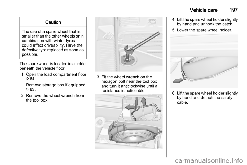
2. Remove the wheel wrench from the tool box.
3. Fit the wheel wrench on the hexagon bolt near the tool box
and turn it anticlockwise until a
resistance is noticeable.
4. Lift the spare wheel holder slightly
by hand and unhook the catch.
5. Lower the spare wheel holder.
6. Lift the spare wheel holder slightly
by hand and detach the safety
cable.
Page 200 of 239
198Vehicle care
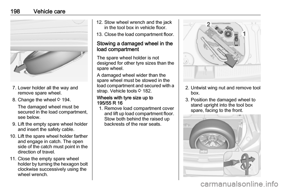
7. Lower holder all the way andremove spare wheel.
8. Change the wheel 3 194.
The damaged wheel must be
secured in the load compartment,
see below.
9. Lift the empty spare wheel holder and insert the safety cable.
10. Lift the spare wheel holder farther
and engage in catch. The open
side of the catch must point in the direction of travel.
11. Close the empty spare wheel holder by turning the hexagon boltclockwise successively using the
wheel wrench.
12. Stow wheel wrench and the jack in the tool box in vehicle floor.
13. Close the load compartment floor.
Stowing a damaged wheel in the
load compartment
The spare wheel holder is not
designed for other tyre sizes than the
spare wheel.
A damaged wheel wider than the
spare wheel must be stowed in the
load compartment and secured with a
strap. Vehicle tools 3 182.Wheels with tyre size up to
195/55 R 16 1. Remove load compartment cover and lift up load compartment floor.
Stow both behind the raised up
backrests of the rear seats.
2. Untwist wing nut and remove tool box.
3. Position the damaged wheel to stand upright into the tool box
spare, facing to the front.
Page 204 of 239
202Vehicle care3. Connect the black lead to thenegative terminal of the booster
battery.
4. Connect the other end of the black
lead to a vehicle grounding point,
such as the engine block or an
engine mounting bolt. Connect as far away from the discharged
vehicle battery as possible,
however at least 60 cm.
Route the leads so that they cannot
catch on rotating parts in the engine
compartment.
To start the engine: 1. Start the engine of the vehicle providing the jump.
2. After five minutes, start the other engine. Start attempts should be
made for no longer than
15 seconds at an interval of one minute.
3. Allow both engines to idle for approx. three minutes with the
leads connected.4. Switch on electrical consumers (e.g. headlights, heated rear
window) of the vehicle receiving
the jump start.
5. Reverse above sequence exactly when removing leads.Towing
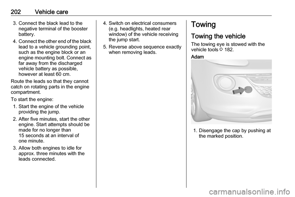
Towing the vehicle The towing eye is stowed with the
vehicle tools 3 182.Adam
1. Disengage the cap by pushing at
the marked position.
Page 205 of 239

Vehicle care203
2. Screw in the towing eye as far asit will go until it stops in a
horizontal position.
3. Attach a tow rope – or better still a
tow rod – to the towing eye.
Adam Rocks
1. Disengage the small cap with a screwdriver at the marked
position.
2. Screw in the towing eye as far as it will go until it stops in a
horizontal position.
3. Attach a tow rope – or better still a
tow rod – to the towing eye.General
The towing eye must only be used for
towing and not for recovering the
vehicle.
Switch on ignition to release steering
wheel lock and to permit operation of
brake lights, horn and windscreen
wiper.
Transmission in neutral.Caution
Drive slowly. Do not drive jerkily.
Excessive tractive force can
damage the vehicle.
When the engine is not running,
considerably more force is needed to
brake and steer.
To prevent the entry of exhaust gases from the towing vehicle, switch on the
air recirculation and close the
windows.