warning light VAUXHALL ADAM 2017.5 Owner's Manual
[x] Cancel search | Manufacturer: VAUXHALL, Model Year: 2017.5, Model line: ADAM, Model: VAUXHALL ADAM 2017.5Pages: 241, PDF Size: 7.33 MB
Page 13 of 241

In brief111Power windows .....................29
2 Exterior mirrors .....................27
3 Cruise control .....................142
Speed limiter ....................... 143
4 Side air vents ...................... 123
5 Turn and lane-change
signals, headlight flash,
low beam and high beam ....110
Exit lighting ......................... 113
Parking lights ...................... 110
Buttons for Driver
Information Centre ................89
6 Instruments .......................... 78
7 Steering wheel controls .......71
8 Driver Information Centre ...... 89
9 Windscreen wiper,
windscreen washer
system, headlight washer
system, rear wiper, rear
washer system ......................72
10 Central locking system ..........22
City mode ............................ 140
Fuel selector ......................... 80Eco button for stop-start
system ................................. 128
Traction Control system .....138
Electronic Stability Control . 139
Parking assist ..................... 145
Seat heating .......................... 36
Heated steering wheel ..........71
11 Colour-Info-Display ..............94
Graphic-Info-Display .............95
12 Hazard warning flashers ....109
Control indicator for airbag
deactivation .......................... 85
Control indicator for front
passenger seat belt .............84
13 Anti-theft alarm system
status LED ........................... 25
14 Centre air vents .................. 123
15 Side air vents passenger
side ..................................... 123
16 Glovebox .............................. 51
Fuse box ............................ 183
17 Climate control system ........ 115
18 Power outlet .......................... 7719AUX input, USB input ...........10
20 Selector lever,
transmission ....................... 132
21 Parking brake ......................137
22 Ignition switch with
steering wheel lock ............126
23 Horn ..................................... 72
Driver airbag ........................ 42
24 Bonnet release lever ..........165
25 Steering wheel adjustment ..71
26 Light switch ........................ 107
Headlight range
adjustment ......................... 109
Rear fog light ...................... 110
Brightness of instrument
panel illumination ................111
Brightness of ambient light 111
Page 15 of 241

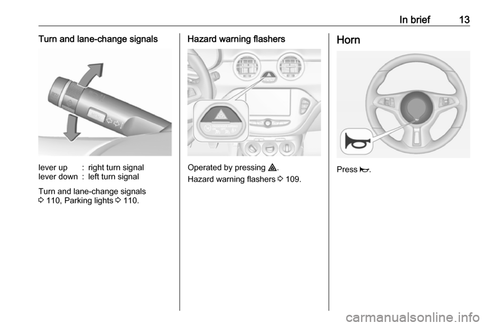
In brief13Turn and lane-change signalslever up:right turn signallever down:left turn signal
Turn and lane-change signals
3 110, Parking lights 3 110.
Hazard warning flashers
Operated by pressing ¨.
Hazard warning flashers 3 109.
Horn
Press j.
Page 28 of 241

26Keys, doors and windowsActivation● Self-activated 30 seconds after locking the vehicle by pressing e
once.
● Directly by pressing e twice
within five seconds.
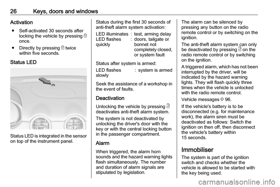
Status LED
Status LED is integrated in the sensor
on top of the instrument panel.
Status during the first 30 seconds of
anti-theft alarm system activation:LED illuminates:test, arming delayLED flashes
quickly:doors, tailgate or
bonnet not
completely closed,
or system fault
Status after system is armed:
LED flashes
slowly:system is armed
Seek the assistance of a workshop in the event of faults.
Deactivation Unlocking the vehicle by pressing c
deactivates anti-theft alarm system.
The system is not deactivated by
unlocking the driver's door with the
key or with the central locking button
in the passenger compartment.
Alarm When triggered, the alarm horn
sounds and the hazard warning lights
flash simultaneously. The number
and duration of alarm signals are
stipulated by legislation.
The alarm can be silenced by
pressing any button on the radio
remote control or by switching on the
ignition.
The anti-theft alarm system can only
be deactivated by pressing c on the
radio remote control or by switching
on the ignition.
A triggered alarm, which has not been interrupted by the driver, will be
indicated by the hazard warning
lights. They will flash quickly three
times when the vehicle is unlocked
with the radio remote control.
Vehicle messages 3 96.
If the vehicle's battery is to be
disconnected (e.g. for maintenance
work), the alarm siren must be
deactivated as follows: Switch the
ignition on then off, then disconnect
the vehicle's battery within
15 seconds.
Immobiliser The system is part of the ignition
switch and checks whether the
vehicle is allowed to be started with
the key being used.
Page 32 of 241

30Keys, doors and windows
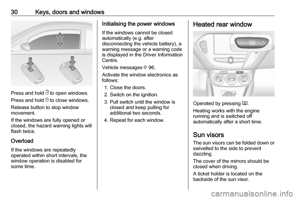
Press and hold c to open windows.
Press and hold e to close windows.
Release button to stop window
movement.
If the windows are fully opened or
closed, the hazard warning lights will
flash twice.
Overload
If the windows are repeatedly
operated within short intervals, the
window operation is disabled for
some time.
Initialising the power windows
If the windows cannot be closed
automatically (e.g. after
disconnecting the vehicle battery), a
warning message or a warning code
is displayed in the Driver Information
Centre.
Vehicle messages 3 96.
Activate the window electronics as
follows:
1. Close the doors.
2. Switch on the ignition.
3. Pull switch until the window is closed and keep pulling for
additional two seconds.
4. Repeat for each window.Heated rear window
Operated by pressing Ü.
Heating works with the engine
running and is switched off
automatically after a short time.
Sun visors The sun visors can be folded down or
swivelled to the side to prevent
dazzling.
The cover of the mirrors should be
closed when driving.
A ticket holder is located on the
backside of the sun visor.
Page 46 of 241

44Seats, restraintsCurtain airbag system
The curtain airbag system consists of an airbag in the roof frame on each
side. The location is identified by the
word AIRBAG on the roof pillars.
The curtain airbag system is triggered in the event of a side-on impact of a
certain severity. The ignition must be
switched on.
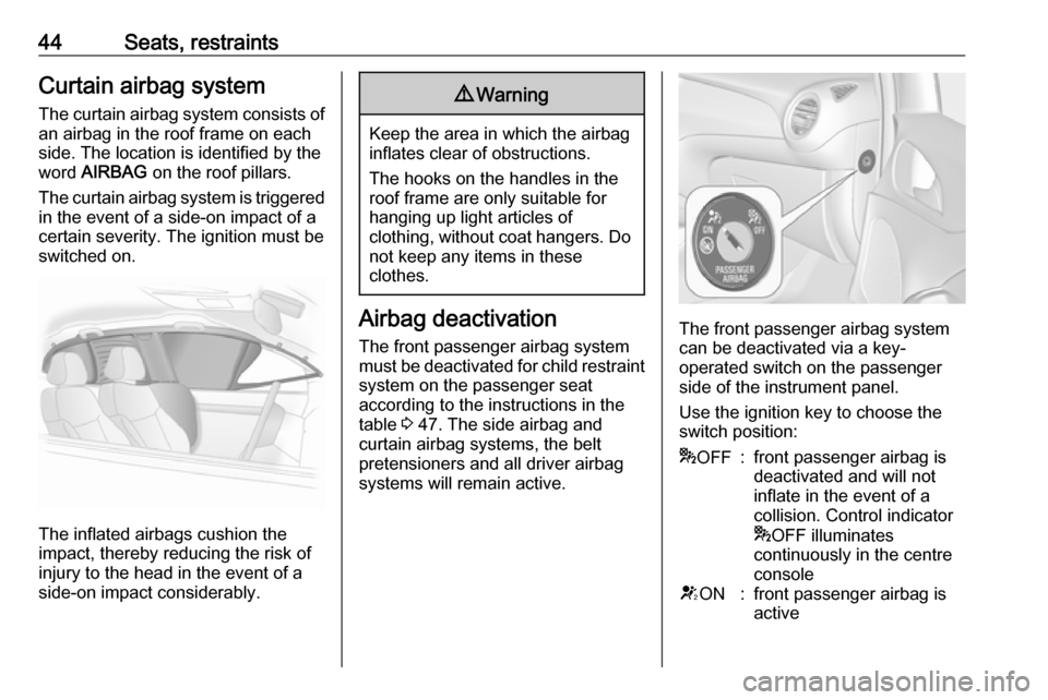
The inflated airbags cushion the
impact, thereby reducing the risk of
injury to the head in the event of a
side-on impact considerably.
9 Warning
Keep the area in which the airbag
inflates clear of obstructions.
The hooks on the handles in the
roof frame are only suitable for
hanging up light articles of
clothing, without coat hangers. Do not keep any items in these
clothes.
Airbag deactivation
The front passenger airbag system must be deactivated for child restraint
system on the passenger seat
according to the instructions in the
table 3 47. The side airbag and
curtain airbag systems, the belt
pretensioners and all driver airbag
systems will remain active.The front passenger airbag system
can be deactivated via a key-
operated switch on the passenger side of the instrument panel.
Use the ignition key to choose the switch position:
* OFF:front passenger airbag is
deactivated and will not
inflate in the event of a
collision. Control indicator
* OFF illuminates
continuously in the centre
consoleV ON:front passenger airbag is
active
Page 55 of 241

Storage53Rear carrier system
Rear carrier system for two
bicycles
The rear carrier system (Flex-Fix
system) allows one bicycle to be attached to an extendable carrier
integrated into the vehicle floor. It is
possible to attach one further bicycle on an adapter. The transportation of
other objects is not permitted.
The maximum load of the rear carrier
system is 50 kg with attached adapter
and 30 kg without attached adapter.
This allows the attachment of an
electrically-powered bicycle to the
rear carrier system. The maximum
load on the adapter is 20 kg.
The wheelbase of a bicycle must not
exceed 1.15 metres. Otherwise the
secure fastening of a bicycle is not
possible.
If not in use, the rear carrier system
must be slid back into the vehicle
floor.
There must not be any objects on the bicycles that could become loose
during transportation.Caution
If the rear carrier system is
extended and the vehicle is fully
loaded, the chassis clearance will
be reduced.
Drive carefully whenever the road has a strong inclination or when
driving over a ramp, bump, etc.
Caution
Consult your bicycle dealer before
attaching bicycles with carbon
frames. The bicycles might get
damaged.
Notice
The tail lights of the vehicle will be
deactivated if the tail lights of the rear carrier system are installed.
Extending
Open the tailgate.
9 Warning
No-one should be in the extension
zone of the rear carrier system,
risk of injury.
Page 56 of 241

54Storage
Pull release lever up. The system
disengages and travels quickly out of
the bumper.
Completely pull out the rear carrier
system until you hear it engage.
Ensure that it is not possible to push in the rear carrier system without
pulling the release lever again.9 Warning
It is only permissible to fit objects
to the rear carrier system if the
system has been correctly
engaged. If the rear carrier system
will not engage correctly, do not fit
objects to the system and slide the system back. Seek the assistance
of a workshop.
Unfold number plate light
Lift the number plate light and fold it
backwards.
Page 61 of 241

Storage59● Without attached adapter:
Push the lever (1) to disengage
and hold.
Pull the rack (2) backwards to
fold the rear carrier system.
● With attached adapter:
9 Warning
Take care when disengaging the
rear carrier system as it will tilt
backwards. Risk of injury.
Hold frame (1) of rear bicycle with
one hand and pull the loop (2) to
disengage.
Hold rear bicycle with both hands and fold the rear carrier system
backwards.
To increase visibility, the tail lights of the vehicle are activated when the
rear carrier system is folded back.
9 Warning
When folding the rear carrier
system forwards again, take care
that the system is engaged
securely.
Removing bicycles
Undo strap retainers on both bicycle
tyres.
Turn knob anticlockwise and remove
mounting brackets.
Detaching adapter 1. Fold in wheel recesses.
2. Unbutton the strap.
Page 64 of 241

62StorageFold in number plate light
Fold number plate light forwards.
Retracting the rear carrier system
Caution
Take care that all foldable parts,
e.g. wheel recesses and mounting brackets, are stowed accurately.
Otherwise the rear carrier system might get damaged when trying to retract it.
Push the release lever up and hold.
Lift the system slightly and push it into the bumper until it engages.
Release lever must return to original
position.
9 Warning
If the system cannot be correctly
engaged, please seek the
assistance of a workshop.
Load compartment
The rear seat backrest is divided into
two parts. Both parts can be folded
down separately.
Load compartment extension
Remove the load compartment cover
if necessary.
Press the catch and push down the
head restraint.
Insert seat belt latch plate into side
holder to protect the belt against
damage.
Page 65 of 241

Storage63
Pull the loop on one or both backrestsand fold them down onto the seat
cushion.
To fold up, raise the backrests into
upright position and let them engage
audibly.
The backrests are properly engaged
when the red marks on both release
loops are not visible.
9 Warning
When folding up, ensure that
backrests are securely locked in
position before driving. Failure to
do so may result in personal injury or damage to load or vehicle in the event of heavy braking or collision.
Hook for carrier bags
Use the hook at the right sidewall of
the load compartment for hanging up carrier bags. Maximum load: 5 kg.
Rear storage
Storage box A closable storage box is located in
the load compartment. The cover is lockable by turning the knob. It must
be locked while driving.
To open, unlock and lift up the cover.
To remove the cover, open it and slide sideways to the left.
The box can be separated by a
divider.
The storage box cover can be loaded
with max. 20 kg.
Removal
To gain access to emergency breakdown equipment or for bulb
replacement of the tail lights, the
storage box must be removed:
● Remove the load compartment cover 3 64.
● Fold down the rear backrests 3 62.
● Open the storage box.