warning light VAUXHALL ADAM 2017.5 Owner's Guide
[x] Cancel search | Manufacturer: VAUXHALL, Model Year: 2017.5, Model line: ADAM, Model: VAUXHALL ADAM 2017.5Pages: 241, PDF Size: 7.33 MB
Page 111 of 241
Lighting109Headlight range adjustment
Manual headlight range
adjustment
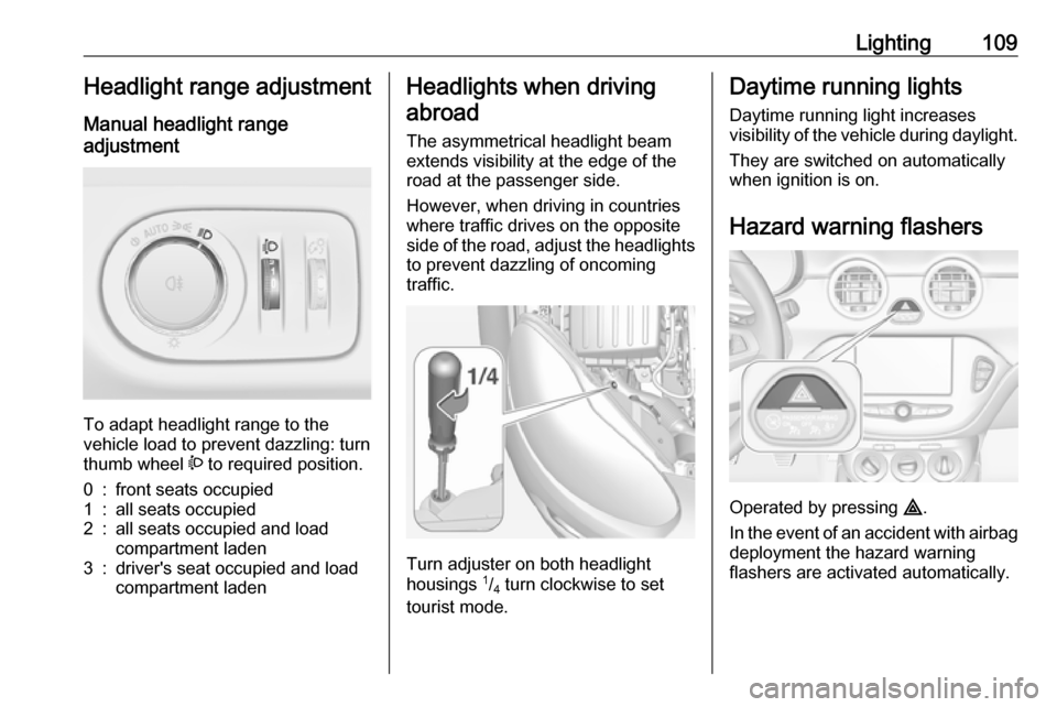
To adapt headlight range to the
vehicle load to prevent dazzling: turn
thumb wheel ? to required position.
0:front seats occupied1:all seats occupied2:all seats occupied and load
compartment laden3:driver's seat occupied and load
compartment ladenHeadlights when driving
abroad
The asymmetrical headlight beam
extends visibility at the edge of the
road at the passenger side.
However, when driving in countries
where traffic drives on the opposite
side of the road, adjust the headlights to prevent dazzling of oncoming
traffic.
Turn adjuster on both headlight
housings 1
/4 turn clockwise to set
tourist mode.
Daytime running lights
Daytime running light increases
visibility of the vehicle during daylight.
They are switched on automatically
when ignition is on.
Hazard warning flashers
Operated by pressing ¨.
In the event of an accident with airbag
deployment the hazard warning
flashers are activated automatically.
Page 119 of 241
Climate control117Cooling n
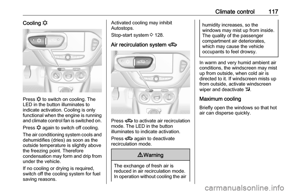
Press n
to switch on cooling. The
LED in the button illuminates to
indicate activation. Cooling is only
functional when the engine is running and climate control fan is switched on.
Press n again to switch off cooling.
The air conditioning system cools and
dehumidifies (dries) as soon as the
outside temperature is slightly above
the freezing point. Therefore
condensation may form and drip from under the vehicle.
If no cooling or drying is required,
switch off the cooling system for fuel
saving reasons.
Activated cooling may inhibit
Autostops.
Stop-start system 3 128.
Air recirculation system 4
Press 4 to activate air recirculation
mode. The LED in the button
illuminates to indicate activation.
Press 4 again to deactivate
recirculation mode.
9 Warning
The exchange of fresh air is
reduced in air recirculation mode.
In operation without cooling the air
humidity increases, so the
windows may mist up from inside.
The quality of the passenger
compartment air deteriorates,
which may cause the vehicle
occupants to feel drowsy.
In warm and very humid ambient air conditions, the windscreen may mist
up from outside, when cold air is
directed to it. If windscreen mists up
from outside, activate windscreen
wiper and deactivate l.
Maximum cooling Briefly open the windows so that hot
air can disperse quickly.
Page 137 of 241

Driving and operating135ParkingThe most recently engaged gear (see
transmission display) remains
engaged when switching off ignition. With N, no gear is engaged.
Therefore always apply the parking
brake when switching off ignition. If
parking brake is not applied, P flashes
in the transmission display and the
key cannot be removed from the
ignition switch. P stops flashing in the
transmission display as soon as the
parking brake is slightly applied.
When the ignition is switched off, the
transmission no longer responds to
movement of the selector lever.
Tyre pressure monitoring system
To start the sensor matching process of the tyre pressure monitoring
system, the selector lever must be
moved and held in position N for
five seconds. P illuminates in the
transmission display to indicate that
the sensor matching process can be
started.
Tyre pressure monitoring system
3 188.Manual mode
If a higher gear is selected when theengine speed is too low, or a lower
gear when the speed is too high, the
shift is not executed. This prevents
the engine from running at too low or too high an engine speed. A warning
message is displayed in the Driver
Information Centre. Vehicle
messages 3 96.
If engine speed is too low, the
transmission automatically shifts to a
lower gear.
If engine speed is too high, the
transmission only switches to a higher gear via kickdown.
When + or - is selected in automatic
mode, the transmission switches to
manual mode and shifts accordingly.
Gear shift indication
The symbol R, with a number
alongside it, is indicated when
gearshifting is recommended for fuel
saving reasons.
Shift indication appears only in
manual mode.Electronic driving
programmes
● Following a cold start, the operating temperature
programme increases engine
speed to quickly bring the
catalytic converter to the required
temperature.
● The adaptive programme tailors gearshifting to the driving
conditions, e.g. greater load or gradients.
Kickdown If the accelerator pedal is pressed
down completely in automatic mode, the transmission shifts to a lower gear
depending on engine speed.
Fault
To prevent damage to the manual transmission automated, the clutch is
engaged automatically at high clutch
temperatures.
Page 138 of 241

136Driving and operatingIn the event of a fault, control indicatorg illuminates. Additionally, a
warning message is displayed in the
Driver Information Centre. Vehicle
messages 3 96.
Continued driving is restricted or not
possible, depending on the fault.
Have the cause of the fault remedied
by a workshop.Brakes
The brake system comprises two
independent brake circuits.
If a brake circuit fails, the vehicle can
still be braked using the other brake
circuit. However, braking effect is
achieved only when the brake pedal
is depressed firmly. Considerably
more force is needed for this. The braking distance is extended. Seek
the assistance of a workshop before
continuing the journey.
When the engine is not running, the
support of the brake servo unit
disappears once the brake pedal has been depressed once or twice.
Braking effect is not reduced, but
braking requires significantly greater
force. It is especially important to bear this in mind when being towed.
Control indicator R 3 86.
Antilock brake system
Antilock brake system (ABS)
prevents the wheels from locking.ABS starts to regulate brake pressure as soon as a wheel shows a tendency to lock. The vehicle remains
steerable, even during hard braking.
ABS control is made apparent
through a pulse in the brake pedal
and the noise of the regulation
process.
For optimum braking, keep the brake
pedal fully depressed throughout the
braking process, despite the fact that
the pedal is pulsating. Do not reduce
the pressure on the pedal.
After starting off the system performs
a self-test which may be audible.
Control indicator u 3 87.
Adaptive brake light
During full braking, all three brake
lights flash for the duration of ABS
control.
Page 139 of 241
Driving and operating137Fault9Warning
If there is a fault in the ABS, the
wheels may be liable to lock due
to braking that is heavier than
normal. The advantages of ABS are no longer available. During
hard braking, the vehicle can no longer be steered and may
swerve.
Have the cause of the fault remedied
by a workshop.
Parking brake
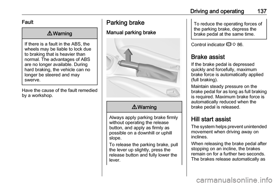
Manual parking brake9 Warning
Always apply parking brake firmly
without operating the release
button, and apply as firmly as
possible on a downhill or uphill
slope.
To release the parking brake, pull
the lever up slightly, press the
release button and fully lower the
lever.
To reduce the operating forces of
the parking brake, depress the
brake pedal at the same time.
Control indicator R 3 86.
Brake assist
If the brake pedal is depressed
quickly and forcefully, maximum
brake force is automatically applied
(full braking).
Maintain steady pressure on the
brake pedal for as long as full braking is required. Maximum brake force is
automatically reduced when the
brake pedal is released.
Hill start assist
The system helps prevent unintended movement when driving away on
inclines.
When releasing the brake pedal after
stopping on an incline, the brakes
remain on for a further two seconds.
The brakes release automatically as
Page 157 of 241

Driving and operating155Side blind spot alert is active from
speeds of 6 mph up to 87 mph.
Driving faster than 87 mph
deactivates the system, indicated by
low lighting warning symbols B in
both exterior mirrors. Reducing the
speed again will extinguish the
warning symbols. If a vehicle is then
detected in the blind zone, the
warning symbols B will illuminate as
normal on the relevant side.
When the vehicle is started, both
exterior mirror displays will briefly
illuminate to indicate that the system
is operating.
The system can be activated or
deactivated in the Info-Display.
Vehicle personalisation 3 99.
Deactivation is indicated by a
message in the Driver Information
Centre.
Detection zones The detection zones start at the rear
bumper and extend approx. three metres rearwards and to the sides.
The height of the zone is between
approx. 0.5 metres and two metres off
the ground.The system is deactivated if the
vehicle is towing a trailer.
Side blind spot alert is designed to
ignore stationary objects, e.g.
guardrails, posts, curbs, walls and
beams. Parked vehicles or oncoming
vehicles are not detected.
Fault
Occasional missed alerts can occur
under normal circumstances and will
increase in wet conditions.
Side blind spot alert does not operate when the left or right corners of the
rear bumper are covered with mud,
dirt, snow, ice, slush, or in heavy
rainstorms. Cleaning instructions
3 208.
In the event of a fault in the system or if the system does not work due to
temporary conditions, a message is
displayed in the Driver Information
Centre. Seek the assistance of a
workshop.Fuel
Fuel for petrol engines Only use unleaded fuel that complies
with European standard EN 228 or
equivalent.
The engine is capable of running with
fuel that contains up to 10% ethanol
(e.g. named E10).
Use fuel with the recommended octane rating. A lower octane rating can reduce engine power and torque
and slightly increases fuel
consumption.Caution
Do not use fuel or fuel additives
that contain metallic compounds
such as manganese-based
additives. This may cause engine
damage.
Page 160 of 241
158Driving and operatingDue to extreme temperatures in
combination with the gas
composition, it may take slightly
longer before the system switches
from petrol to gas mode.
In extreme situations, the system may
also switch back to petrol mode if the
minimum requirements are not
fulfilled. If conditions allow, it might be possible to manually switch back to
liquid gas operation.
Seek the assistance of a workshop in
the event of all other faults.Caution
Repairs and adjustments may only be made by trained specialists in
order to maintain the safety and
warranty on the LPG system.
Liquid gas is given a particular odour
(odorised) so that any leaks can be
detected easily.
9 Warning
If you smell gas in the vehicle or in
the immediate vicinity, switch to petrol mode immediately. No
smoking. No naked flames or
ignition sources.
If the gas odour persists, do not start
the engine. Have the cause of the
fault remedied by a workshop.
When using underground car parks,
follow the instructions of the operator
and local laws.
Notice
In the event of an accident, switch off
the ignition and lights.
Refuelling
9 Danger
Before refuelling, switch off the
ignition.
Follow the operating and safety
instructions of the filling station
when refuelling.
9 Danger
Fuel is flammable and explosive.
No smoking. No naked flames or
sparks.
If you can smell fuel in your
vehicle, have the cause of this
remedied immediately by a
workshop.
Caution
In case of misfuelling, do not
switch on ignition.
Fuel filler flap is located at right rear
side of the vehicle.
Page 192 of 241
190Vehicle careEach time the tyres are replaced, tyrepressure monitoring system sensors
must be dismounted and serviced. For the screwed sensor; replace
valve core and sealing ring. For the
clipped sensor; replace complete
valve stem.
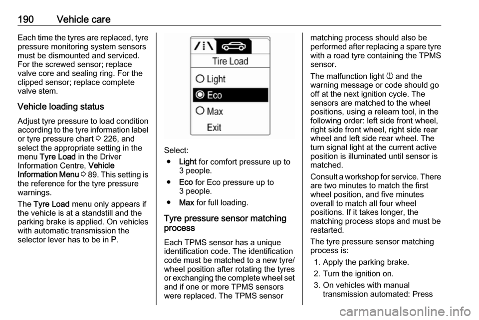
Vehicle loading status
Adjust tyre pressure to load condition according to the tyre information labelor tyre pressure chart 3 226, and
select the appropriate setting in the menu Tyre Load in the Driver
Information Centre, Vehicle
Information Menu 3 89 . This setting is
the reference for the tyre pressure
warnings.
The Tyre Load menu only appears if
the vehicle is at a standstill and the
parking brake is applied. On vehicles
with automatic transmission the
selector lever has to be in P.
Select:
● Light for comfort pressure up to
3 people.
● Eco for Eco pressure up to
3 people.
● Max for full loading.
Tyre pressure sensor matching
process
Each TPMS sensor has a unique
identification code. The identification
code must be matched to a new tyre/ wheel position after rotating the tyres
or exchanging the complete wheel set
and if one or more TPMS sensors
were replaced. The TPMS sensor
matching process should also be
performed after replacing a spare tyre with a road tyre containing the TPMS
sensor.
The malfunction light w and the
warning message or code should go
off at the next ignition cycle. The
sensors are matched to the wheel
positions, using a relearn tool, in the
following order: left side front wheel,
right side front wheel, right side rear
wheel and left side rear wheel. The
turn signal light at the current active
position is illuminated until sensor is
matched.
Consult a workshop for service. There
are two minutes to match the first
wheel position, and five minutes
overall to match all four wheel
positions. If it takes longer, the
matching process stops and must be
restarted.
The tyre pressure sensor matching
process is:
1. Apply the parking brake.
2. Turn the ignition on.
3. On vehicles with manual transmission automated: Press
Page 199 of 241
Vehicle care197Wheel changing
Make the following preparations and observe the following information:
● Park the vehicle on a level, firm and non-skid surface. The front
wheels must be in the straight- ahead position.
● Apply the parking brake and engage first gear or reverse gear.
● Never change more than one wheel at once.
● Use the jack only to change wheels in case of puncture, not
for seasonal winter or summer
tyre change.
● The jack is maintenance-free.
● If the ground on which the vehicle
is standing is soft, a solid board
(max. 1 cm thick) should be
placed under the jack.
● Take heavy objects out of the vehicle before jacking up.
● No people or animals may be in the vehicle when it is jacked-up.
● Never crawl under a jacked-up vehicle.●Do not start the vehicle when it is
raised on the jack.
● Before screwing in the wheel bolts, clean them and lightly coat
the taper of each wheel bolt with
commercially available grease.9 Warning
Do not grease the thread of the
wheel bolt.
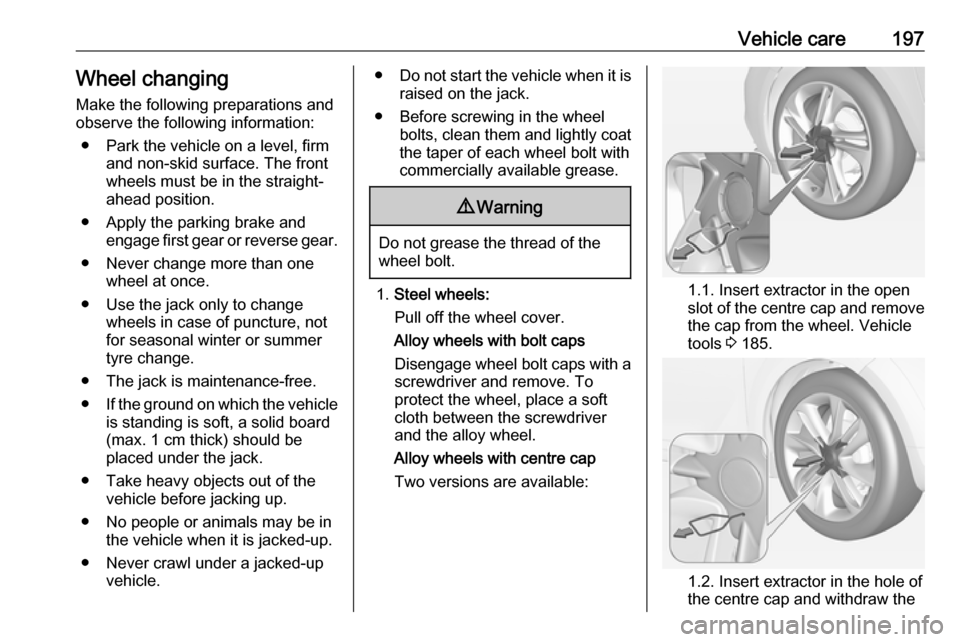
1. Steel wheels:
Pull off the wheel cover.
Alloy wheels with bolt caps Disengage wheel bolt caps with a
screwdriver and remove. To
protect the wheel, place a soft
cloth between the screwdriver
and the alloy wheel.
Alloy wheels with centre cap
Two versions are available:1.1. Insert extractor in the open
slot of the centre cap and remove the cap from the wheel. Vehicle
tools 3 185.
1.2. Insert extractor in the hole of
the centre cap and withdraw the
Page 237 of 241

235Convex shape .............................. 27
Coolant and antifreeze ...............213
Cruise control ...................... 89, 142
Cupholders .................................. 51
Curtain airbag system .................. 44
D
Danger, Warnings and Cautions ...4
Daytime running lights ...............109
Declaration of conformity ............228
Door open .................................... 89
Doors ............................................ 24
Driver assistance systems ..........142
Driver Information Centre .............89
Driving hints ................................ 125
E Electric adjustment ......................27
Electrical system......................... 180
Electronic climate control system 118
Electronic driving programmes ..135
Electronic Stability Control.......... 139
Electronic Stability Control and Traction Control system ............87
Electronic Stability Control off....... 87 End-of-life vehicle recovery .......164
Engine compartment fuse box ...181
Engine coolant ........................... 167
Engine coolant temperature gauge ....................................... 80
Engine data ............................... 220Engine exhaust .......................... 131
Engine identification ...................216
Engine oil ................... 166, 213, 217
Engine oil pressure ......................88
Entry lighting .............................. 113
Event data recorders ..................232
Exit lighting ................................ 113
Exterior care .............................. 208
Exterior light ................................. 89
Exterior lighting ....................12, 107
Exterior mirrors ............................. 27
F Fault ........................................... 135
First aid ......................................... 67
First aid kit ................................... 67
Fixed air vents ........................... 123
Flex-Fix system ............................ 53
Folding mirrors ............................. 27
Front airbag system .....................42
Front seats.................................... 33 Front storage ................................ 52
Front turn signal lights ...............173
Fuel............................................. 155
Fuel consumption - CO 2-
Emissions ............................... 162
Fuel for liquid gas operation .......156
Fuel for petrol engines ...............155
Fuel gauge ................................... 79Fuel selector ................................ 80
Fuses ......................................... 180
G Gauges ......................................... 78
Glass panel .................................. 31
Glovebox ..................................... 51
Graphic-Info-Display .....................95
H Halogen headlights ....................171
Hand brake ......................... 136, 137
Hazard warning flashers ............109
Headlight flash ........................... 108
Headlight range adjustment ......109
Headlights................................... 107
Headlights when driving abroad 109
Head restraint adjustment .............8
Head restraints ............................ 32
Heated mirrors ............................. 28
Heated rear window ..................... 30
Heated steering wheel .................71
Heating ........................................ 36
Heating and ventilation system . 115
High beam ........................... 89, 108
Hill start assist ........................... 137
Horn ....................................... 13, 72
I
Identification plate .....................216
Ignition switch positions .............126