warning VAUXHALL ADAM 2017.5 Manual PDF
[x] Cancel search | Manufacturer: VAUXHALL, Model Year: 2017.5, Model line: ADAM, Model: VAUXHALL ADAM 2017.5Pages: 241, PDF Size: 7.33 MB
Page 157 of 241

Driving and operating155Side blind spot alert is active from
speeds of 6 mph up to 87 mph.
Driving faster than 87 mph
deactivates the system, indicated by
low lighting warning symbols B in
both exterior mirrors. Reducing the
speed again will extinguish the
warning symbols. If a vehicle is then
detected in the blind zone, the
warning symbols B will illuminate as
normal on the relevant side.
When the vehicle is started, both
exterior mirror displays will briefly
illuminate to indicate that the system
is operating.
The system can be activated or
deactivated in the Info-Display.
Vehicle personalisation 3 99.
Deactivation is indicated by a
message in the Driver Information
Centre.
Detection zones The detection zones start at the rear
bumper and extend approx. three metres rearwards and to the sides.
The height of the zone is between
approx. 0.5 metres and two metres off
the ground.The system is deactivated if the
vehicle is towing a trailer.
Side blind spot alert is designed to
ignore stationary objects, e.g.
guardrails, posts, curbs, walls and
beams. Parked vehicles or oncoming
vehicles are not detected.
Fault
Occasional missed alerts can occur
under normal circumstances and will
increase in wet conditions.
Side blind spot alert does not operate when the left or right corners of the
rear bumper are covered with mud,
dirt, snow, ice, slush, or in heavy
rainstorms. Cleaning instructions
3 208.
In the event of a fault in the system or if the system does not work due to
temporary conditions, a message is
displayed in the Driver Information
Centre. Seek the assistance of a
workshop.Fuel
Fuel for petrol engines Only use unleaded fuel that complies
with European standard EN 228 or
equivalent.
The engine is capable of running with
fuel that contains up to 10% ethanol
(e.g. named E10).
Use fuel with the recommended octane rating. A lower octane rating can reduce engine power and torque
and slightly increases fuel
consumption.Caution
Do not use fuel or fuel additives
that contain metallic compounds
such as manganese-based
additives. This may cause engine
damage.
Page 160 of 241
158Driving and operatingDue to extreme temperatures in
combination with the gas
composition, it may take slightly
longer before the system switches
from petrol to gas mode.
In extreme situations, the system may
also switch back to petrol mode if the
minimum requirements are not
fulfilled. If conditions allow, it might be possible to manually switch back to
liquid gas operation.
Seek the assistance of a workshop in
the event of all other faults.Caution
Repairs and adjustments may only be made by trained specialists in
order to maintain the safety and
warranty on the LPG system.
Liquid gas is given a particular odour
(odorised) so that any leaks can be
detected easily.
9 Warning
If you smell gas in the vehicle or in
the immediate vicinity, switch to petrol mode immediately. No
smoking. No naked flames or
ignition sources.
If the gas odour persists, do not start
the engine. Have the cause of the
fault remedied by a workshop.
When using underground car parks,
follow the instructions of the operator
and local laws.
Notice
In the event of an accident, switch off
the ignition and lights.
Refuelling
9 Danger
Before refuelling, switch off the
ignition.
Follow the operating and safety
instructions of the filling station
when refuelling.
9 Danger
Fuel is flammable and explosive.
No smoking. No naked flames or
sparks.
If you can smell fuel in your
vehicle, have the cause of this
remedied immediately by a
workshop.
Caution
In case of misfuelling, do not
switch on ignition.
Fuel filler flap is located at right rear
side of the vehicle.
Page 162 of 241

160Driving and operating
Screw the required adapter hand-
tight onto the filler neck.
ACME Adapter: Screw the nut of the
filling nozzle onto the adapter. Press
locking lever on filler nozzle down.
DISH filler neck: Place the filler nozzle
into the adapter. Press locking lever
on filler nozzle down.
Bayonet filler neck: Place filler nozzle
on the adapter and turn clockwise or
anticlockwise through one quarter
turn. Pull locking lever of filler nozzle
fully.
EURO filler neck: Press the filler
nozzle onto the adapter until it
engages.
Press the button at the liquid gas
supply point. The filling system stops
or begins to run slowly when 80% of
the tank volume is reached
(maximum fill level).
Release button on filling system and
the filling process stops. Release the
locking lever and remove the filler
nozzle. A small quantity of liquid gas
may escape.
Remove adapter and stow securely in vehicle.Fit protective cap to prevent the
penetration of foreign bodies into the
filler opening and the system.9 Warning
Due to the system design, an
escape of liquid gas after
releasing the locking lever is
unavoidable. Avoid inhaling.
9 Warning
The liquid gas tank should only be
filled to 80% capacity, for safety
reasons.
The multivalve on the liquid gas tank
automatically limits the fill quantity. If
a larger quantity is added, we
recommend not exposing the vehicle
to the sun until the excess amount
has been used up.
Page 167 of 241

Vehicle care165Vehicle checks
Performing work9 Warning
Only perform engine compartment
checks when the ignition is off.
The cooling fan may start
operating even if the ignition is off.
9 Danger
The ignition system uses
extremely high voltage. Do not
touch.
Bonnet
Opening
Pull the release lever and return it to
its original position.
Push the safety catch upwards and open the bonnet.
Secure the bonnet support.
Page 169 of 241
Vehicle care167Engine coolant
The coolant provides freeze
protection down to approx. -28 °C. In
northern countries with very low
temperatures the factory filled coolant
provides frost protection down to
approx. -37 °C.Caution
Only use approved antifreeze.
Coolant and antifreeze 3 213.
Coolant level
Caution
Too low a coolant level can cause engine damage.
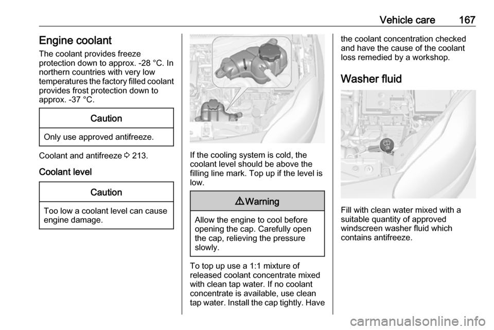
If the cooling system is cold, the
coolant level should be above the
filling line mark. Top up if the level is
low.
9 Warning
Allow the engine to cool before
opening the cap. Carefully open
the cap, relieving the pressure
slowly.
To top up use a 1:1 mixture of
released coolant concentrate mixed
with clean tap water. If no coolant
concentrate is available, use clean
tap water. Install the cap tightly. Have
the coolant concentration checked
and have the cause of the coolant
loss remedied by a workshop.
Washer fluid
Fill with clean water mixed with a
suitable quantity of approved
windscreen washer fluid which
contains antifreeze.
Page 170 of 241
168Vehicle careCaution
Only washer fluid with a sufficient
antifreeze concentration provides
protection at low temperatures or
a sudden drop in temperature.
Washer fluid 3 213.
Brakes In the event of minimum thickness of
the brake lining, a squealing noise
sounds during braking.
Continued driving is possible but
have the brake lining replaced as
soon as possible.
Once new brake linings are installed,
do not brake unnecessarily hard for
the first few journeys.
Brake fluid
9 Warning
Brake fluid is poisonous and
corrosive. Avoid contact with eyes,
skin, fabrics and painted surfaces.
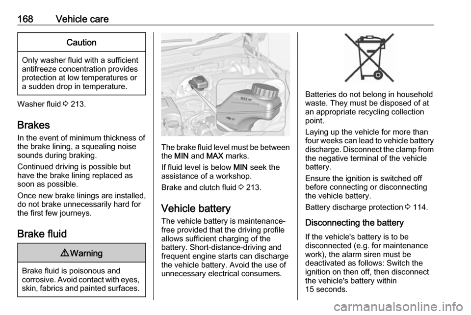
The brake fluid level must be betweenthe MIN and MAX marks.
If fluid level is below MIN seek the
assistance of a workshop.
Brake and clutch fluid 3 213.
Vehicle battery
The vehicle battery is maintenance-
free provided that the driving profile
allows sufficient charging of the
battery. Short-distance-driving and
frequent engine starts can discharge
the vehicle battery. Avoid the use of
unnecessary electrical consumers.
Batteries do not belong in household
waste. They must be disposed of at
an appropriate recycling collection
point.
Laying up the vehicle for more than
four weeks can lead to vehicle battery
discharge. Disconnect the clamp from
the negative terminal of the vehicle
battery.
Ensure the ignition is switched off
before connecting or disconnecting
the vehicle battery.
Battery discharge protection 3 114.
Disconnecting the battery If the vehicle's battery is to be
disconnected (e.g. for maintenance
work), the alarm siren must be
deactivated as follows: Switch the ignition on then off, then disconnect
the vehicle's battery within
15 seconds.
Page 171 of 241
Vehicle care169Replacing the vehicle batteryNotice
Any deviation from the instructions
given in this section may lead to
temporary deactivation of the stop-
start system.
When the vehicle battery is being
replaced, please ensure that there
are no open ventilation holes in the
vicinity of the positive terminal. If a
ventilation hole is open in this area, it
must be closed off with a dummy cap,
and the ventilation in the vicinity of the negative terminal must be opened.
Only use batteries that allow the fuse
box to be mounted above the vehicle
battery.
In vehicles with an AGM (Absorptive
Glass Mat) battery, make sure to
have the battery replaced with
another AGM battery.
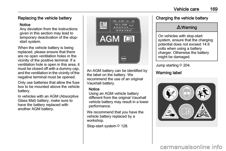
An AGM battery can be identified by
the label on the battery. We
recommend the use of an original
Vauxhall battery.
Notice
Using an AGM vehicle battery
different from the original Vauxhall
vehicle battery may result in a lower
performance.
We recommend that you have the vehicle battery replaced by a
workshop.
Stop-start system 3 128.
Charging the vehicle battery9 Warning
On vehicles with stop-start
system, ensure that the charging potential does not exceed 14.6
volts when using a battery
charger. Otherwise the battery
might be damaged.
Jump starting 3 204.
Warning label
Page 188 of 241
186Vehicle careOn version with subwoofer box, the
tools and the towing eye are located
together with the tyre repair kit and
the warning triangle in the box below
the floor cover. To gain access,
remove floor cover: fold rear part to
the front and pull out the cover to the
rear 3 65.
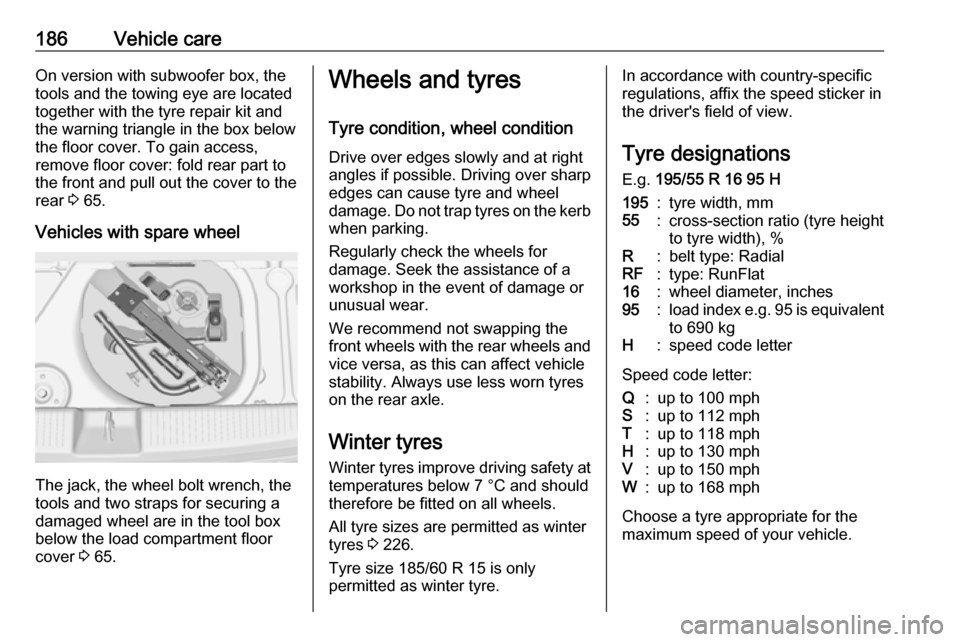
Vehicles with spare wheel
The jack, the wheel bolt wrench, the
tools and two straps for securing a
damaged wheel are in the tool box
below the load compartment floor
cover 3 65.
Wheels and tyres
Tyre condition, wheel condition Drive over edges slowly and at right
angles if possible. Driving over sharp
edges can cause tyre and wheel
damage. Do not trap tyres on the kerb when parking.
Regularly check the wheels for
damage. Seek the assistance of a
workshop in the event of damage or
unusual wear.
We recommend not swapping the
front wheels with the rear wheels and vice versa, as this can affect vehicle
stability. Always use less worn tyres
on the rear axle.
Winter tyres
Winter tyres improve driving safety at temperatures below 7 °C and should
therefore be fitted on all wheels.
All tyre sizes are permitted as winter
tyres 3 226.
Tyre size 185/60 R 15 is only
permitted as winter tyre.In accordance with country-specific
regulations, affix the speed sticker in
the driver's field of view.
Tyre designations
E.g. 195/55 R 16 95 H195:tyre width, mm55:cross-section ratio (tyre height
to tyre width), %R:belt type: RadialRF:type: RunFlat16:wheel diameter, inches95:load index e.g. 95 is equivalent
to 690 kgH:speed code letter
Speed code letter:
Q:up to 100 mphS:up to 112 mphT:up to 118 mphH:up to 130 mphV:up to 150 mphW:up to 168 mph
Choose a tyre appropriate for the
maximum speed of your vehicle.
Page 189 of 241

Vehicle care187The maximum speed is achievable at
kerb weight with driver (75 kg) plus
125 kg payload. Optional equipment
could reduce the maximum speed of
the vehicle.
Performance 3 222.
Directional tyres Directional tyres must be mounted so
that they rotate in the correct
direction. The proper rotation
direction is indicated by a symbol
(e.g. an arrow) on the sidewall.
Tyre pressure
Check the pressure of cold tyres at
least every 14 days and before any
long journey. Do not forget the spare
wheel.
This also applies to vehicles with tyre pressure monitoring system.
Unscrew the valve cap.
Tyre pressure 3 226.
The tyre pressure information label
on the right door frame indicates the original equipment tyres and thecorrespondent tyre pressures.
The tyre pressure data refers to cold
tyres. It applies to summer and winter
tyres.
The ECO tyre pressure serves to
achieve the smallest amount of fuel
consumption possible.
Incorrect tyre pressures will impair
safety, vehicle handling, comfort and fuel economy and will increase tyre
wear.
The tyre pressure tables show all
possible tyre combinations 3 226.
Identify the respective tyre. For the tyres approved for your
vehicle, refer to the EEC Certificate of Conformity provided with your vehicle
or other national registration
documents.
The driver is responsible for correct
adjustment of tyre pressure.9 Warning
If the pressure is too low, this can
result in considerable tyre warm-
up and internal damage, leading to tread separation and even to tyre
blow-out at high speeds.
9 Warning
For specific tyres the
recommended tyre pressure as
shown in the tyre pressure table
may exceed the maximum tyre
pressure as indicated on the tyre.
Never exceed the maximum tyre
pressure as indicated on the tyre.
Page 191 of 241

Vehicle care189
Turn the adjuster wheel to select the
tyre pressure monitoring system.
System status and pressure warnings
are displayed by a message with the
corresponding tyre flashing in the
Driver Information Centre.
The system considers the tyre
temperature for the warnings.
Temperature dependency 3 187.A detected low tyre pressure
condition is indicated by the control
indicator w 3 88.
If w illuminates, stop as soon as
possible and inflate the tyres as
recommended 3 226.
If w flashes for 60-90 seconds then
illuminates continuously, there is a
fault in the system. Consult a
workshop.
After inflating, some driving may be
required to update the tyre pressure
values in the Driver Information
Centre. During this time w may
illuminate.
If w illuminates at lower temperatures
and extinguishes after some driving,
this could be an indicator for
approaching a low tyre pressure
condition. Check tyre pressure.
Vehicle messages 3 96.
If the tyre pressure must be reduced or increased, switch off ignition.
Only mount wheels with pressure
sensors, otherwise the tyre pressure
will not be displayed and w
illuminates continuously.
A spare wheel or temporary spare
wheel is not equipped with pressure
sensors. The tyre pressure
monitoring system is not operational
for these tyres. Control indicator w
illuminates. For the further three
tyres, the system remains
operational.
The use of commercially-available
liquid tyre repair kits can impair the
function of the system. Factory-
approved repair kits can be used.
Operating electronic devices or being
close to facilities using similar wave
frequencies could disrupt the tyre
pressure monitoring system.