ECU VAUXHALL ANTARA 2015 User Guide
[x] Cancel search | Manufacturer: VAUXHALL, Model Year: 2015, Model line: ANTARA, Model: VAUXHALL ANTARA 2015Pages: 223, PDF Size: 6.07 MB
Page 72 of 223
70Storage
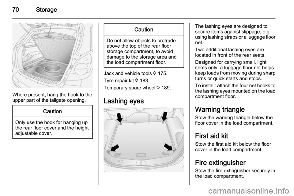
Where present, hang the hook to the
upper part of the tailgate opening.
Caution
Only use the hook for hanging up
the rear floor cover and the height adjustable cover.
Caution
Do not allow objects to protrude
above the top of the rear floor
storage compartment, to avoid
damage to the storage area and
the load compartment floor.
Jack and vehicle tools 3 175.
Tyre repair kit 3 183.
Temporary spare wheel 3 189.
Lashing eyes
The lashing eyes are designed to
secure items against slippage, e.g.
using lashing straps or a luggage floor
net.
Two additional lashing eyes are
located in front of the rear seats.
Designed for carrying small, light
items only, a luggage floor net helps keep loads from moving during sharp turns or quick starts and stops.
To install: attach the four net hooks to
the lashing eyes mounted on the load
compartment floor.
Warning triangle Stow the warning triangle below the
floor cover in the load compartment.
First aid kit Stow the first aid kit below the floor
cover in the load compartment.
Fire extinguisher
Stow the fire extinguisher securely in
the load compartment.
Page 73 of 223

Storage71Roof rack system
Roof rack For safety reasons and to avoiddamage to the roof, the vehicle
approved roof rack system is
recommended. For further
information contact a workshop.
Fasten the roof rack to the roof rails following the instructions that
accompany the system, ensuring that
the roof load is evenly distributed over the side or cross rails.
Loads must not be placed on the roof
surface. To prevent damage or loss,
check frequently that roof loads are
securely fastened.
Driving with a roof load affects the
vehicle centre of gravity; drive
carefully in crosswinds and do not
drive at high speeds.
Remove the roof rack when not in use.Loading information
■ Heavy objects in the load compartment should be evenly
distributed and placed as far
forward as possible. Ensure the
backrests are securely engaged. If
objects can be stacked, the heavier
objects should be placed at the bottom.
With rear seats in the folded
position, objects must not be
stacked higher than the seat
backrests.
■ Secure objects with lashing straps attached to lashing eyes 3 70.
■ Secure loose objects in the load compartment, e.g. with a luggage
floor net, to prevent sliding.
■ When transporting objects in the load compartment, the backrests ofthe rear seats must not be angled
forward.
■ Do not allow the load to protrude above the upper edge of the
backrests.■ Do not place any objects on the load compartment cover or the
instrument panel, and do not cover
the sensor on top of the instrument
panel.
■ The load must not obstruct the operation of the pedals, electrical
parking brake and gear selector, or hinder the freedom of movement ofthe driver. Do not place any
unsecured objects in the interior.
■ Do not drive with an open load compartment.9 Warning
Always make sure that the load in
the vehicle is securely stowed.
Otherwise objects can be thrown
around inside the vehicle and
cause personal injury or damage
to the load or vehicle.
■ The payload is the difference between the permitted gross
vehicle weight (see identification
plate 3 201) and the EC kerb
weight.
Page 74 of 223

72Storage
To calculate the EC kerb weight,
enter the data for your vehicle in the
Weights table at the front of this
manual.
The EC kerb weight includes
weights for the driver (68 kg),
luggage (7 kg) and all fluids (tank
90 % full).
Optional equipment and
accessories increase the kerb
weight.
■ Driving with a roof load increases the sensitivity of the vehicle to
cross-winds and has a detrimental
effect on vehicle handling due to the vehicle's higher centre of
gravity. Distribute the load evenly
and secure it properly with retaining
straps. Adjust the tyre pressure and
vehicle speed according to the load conditions. Check and retighten the
straps frequently.
Do not drive faster than 75 mph.
The permissible roof load is
100 kg. The roof load is the
combined weight of the roof rack
and the load.
Page 93 of 223

Instruments and controls91
Brake pedal needs to be depressed
to release the electrical parking brake
3 137.
Clutch pedal needs to be depressed
to restart the engine.
Stop-start system 3 125.
High beam C illuminates blue.
Illuminated when high beam is on and during headlight flash 3 107.
Automatic headlight
levelling system
q illuminates yellow
Illuminates during driving to indicate a fault that requires immediate
attention. Seek the assistance of a
workshop as soon as possible.
Automatic headlight range
adjustment 3 107.
Fog light
> illuminates green.Illuminates when the front fog lights
are switched on 3 109.
Rear fog light
r illuminates yellow.
Illuminates when the rear fog light is
switched on 3 110.
Cruise control
m illuminates yellow or green.
Illuminates yellow
The system is ready for operation.
Illuminates green
A certain speed is stored.
Cruise control 3 141.
Speed warning
à illuminates yellow.
In vehicles equipped with the
overspeed warning light, when
vehicle speed exceeds 75 mph,
control indicator à flashes,accompanied by a warning chime, to
warn the driver to reduce speed as
appropriate.
Trailer indicator á illuminates green.
Illuminates when a trailer is
connected to the vehicle 3 147.
Bonnet open
/ illuminates red.
Illuminates when the bonnet is open.
Stop-start system 3 125.
Door open ( illuminates red.
Illuminates when a door is open or not
securely latched.
Tailgate open
1 illuminates red.
Illuminates when tailgate is open or
not securely latched 3 23.
Page 94 of 223
92Instruments and controlsAnti-theft alarm system
a illuminates yellow.
Illuminates when alarm system
monitoring of the passenger
compartment and vehicle inclination
has been switched off with button
a in the roof lining.
Anti-theft alarm system 3 25.Information displays
Board-Info-Display
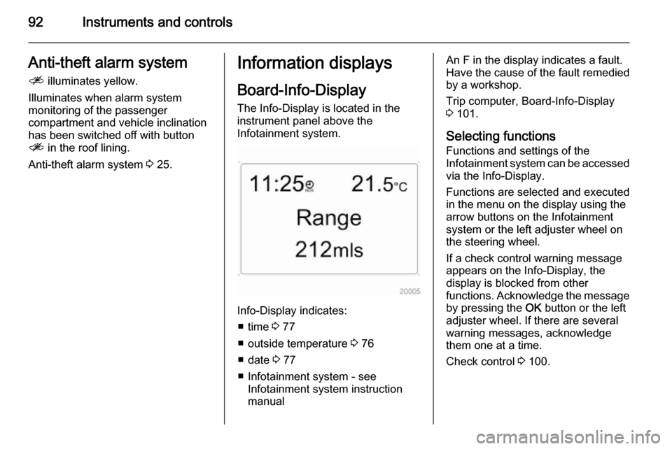
The Info-Display is located in the
instrument panel above the
Infotainment system.
Info-Display indicates:
■ time 3 77
■ outside temperature 3 76
■ date 3 77
■ Infotainment system - see Infotainment system instruction
manual
An F in the display indicates a fault.
Have the cause of the fault remedied by a workshop.
Trip computer, Board-Info-Display
3 101.
Selecting functions
Functions and settings of the
Infotainment system can be accessed via the Info-Display.
Functions are selected and executed
in the menu on the display using the
arrow buttons on the Infotainment
system or the left adjuster wheel on
the steering wheel.
If a check control warning message
appears on the Info-Display, the
display is blocked from other
functions. Acknowledge the message
by pressing the OK button or the left
adjuster wheel. If there are several
warning messages, acknowledge
them one at a time.
Check control 3 100.
Page 97 of 223
Instruments and controls95
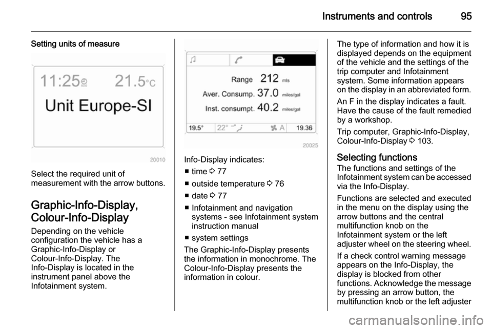
Setting units of measure
Select the required unit of
measurement with the arrow buttons.
Graphic-Info-Display,
Colour-Info-Display Depending on the vehicle
configuration the vehicle has a
Graphic-Info-Display or
Colour-Info-Display. The
Info-Display is located in the
instrument panel above the
Infotainment system.
Info-Display indicates:
■ time 3 77
■ outside temperature 3 76
■ date 3 77
■ Infotainment and navigation systems - see Infotainment systeminstruction manual
■ system settings
The Graphic-Info-Display presents
the information in monochrome. The
Colour-Info-Display presents the
information in colour.
The type of information and how it is
displayed depends on the equipment
of the vehicle and the settings of the
trip computer and Infotainment
system. Some information appears
on the display in an abbreviated form.
An F in the display indicates a fault.
Have the cause of the fault remedied
by a workshop.
Trip computer, Graphic-Info-Display,
Colour-Info-Display 3 103.
Selecting functions
The functions and settings of the
Infotainment system can be accessed
via the Info-Display.
Functions are selected and executed
in the menu on the display using the
arrow buttons and the central
multifunction knob on the
Infotainment system or the left
adjuster wheel on the steering wheel.
If a check control warning message
appears on the Info-Display, the
display is blocked from other
functions. Acknowledge the message by pressing an arrow button, the
multifunction knob or the left adjuster
Page 134 of 223
132Driving and operating
transmission will automatically shift toa lower gear, even in manual mode,
to prevent the engine from stalling.
If a higher gear is selected when
vehicle speed is too low, or a lower
gear when vehicle speed is too high,
the shift is not executed.
In manual mode, no automatic
shifting to a higher gear takes place
at high engine revolutions.
Gears can be skipped by moving the
selector lever repeatedly at short
intervals.
After stopping, 1st gear is
automatically selected. When starting
on slippery surfaces, tip selector lever forwards to engage 2nd gear.
To move back to position D, move
selector lever back to the right.
Electronic driving
programmes ■ Following a cold start, the operating
temperature programme increasesengine speed to quickly bring the
catalytic converter to the required
temperature.Kickdown
In both automatic and manual modes, if the accelerator pedal is pressed
down completely the transmission
shifts to a lower gear depending on
engine speed. Full engine power is
available for acceleration.
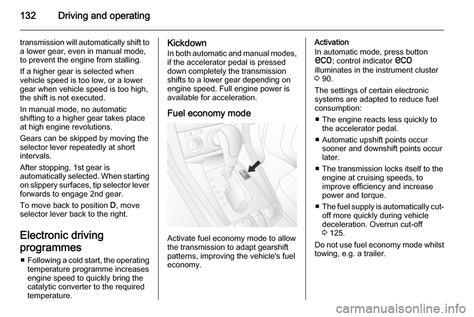
Fuel economy mode
Activate fuel economy mode to allow
the transmission to adapt gearshift
patterns, improving the vehicle's fuel
economy.
Activation
In automatic mode, press button
s ; control indicator s
illuminates in the instrument cluster 3 90.
The settings of certain electronic
systems are adapted to reduce fuel
consumption:
■ The engine reacts less quickly to the accelerator pedal.
■ Automatic upshift points occur sooner and downshift points occur
later.
■ The transmission locks itself to the engine at cruising speeds, to
improve efficiency and increase
power and torque.
■ The fuel supply is automatically cut-
off more quickly during vehicle
deceleration. Overrun cut-off
3 125.
Do not use fuel economy mode whilst towing, e.g. a trailer.
Page 167 of 223
Vehicle care165
1. Remove 2 screws from panel onunderside of vehicle below front
fog lights and remove panel.
2. Disconnect harness connector from bulb holder and rotate bulb
holder anticlockwise.
3. Remove bulb holder from lamp assembly, rotate bulb
anticlockwise and remove from
bulb holder.
4. Insert new bulb into bulb holder and rotate it clockwise.
5. Reinstall bulb holder in lamp assembly and reconnect harnessconnector.
6. Reinstall panel to underside of vehicle using 2 screws removed
earlier.Tail lights
Rear brake, tail, turn signal,
reverse and fog tail light
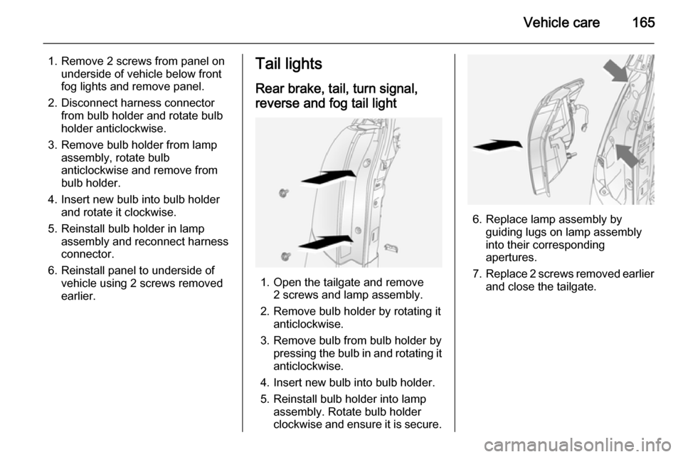
1. Open the tailgate and remove 2 screws and lamp assembly.
2. Remove bulb holder by rotating it anticlockwise.
3. Remove bulb from bulb holder by pressing the bulb in and rotating it
anticlockwise.
4. Insert new bulb into bulb holder.
5. Reinstall bulb holder into lamp assembly. Rotate bulb holder
clockwise and ensure it is secure.
6. Replace lamp assembly by guiding lugs on lamp assembly
into their corresponding
apertures.
7. Replace 2 screws removed earlier
and close the tailgate.
Page 168 of 223
166Vehicle careSide turn signal lights
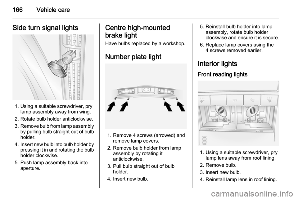
1. Using a suitable screwdriver, prylamp assembly away from wing.
2. Rotate bulb holder anticlockwise.
3. Remove bulb from lamp assembly
by pulling bulb straight out of bulb holder.
4. Insert new bulb into bulb holder by
pressing it in and rotating the bulb holder clockwise.
5. Push lamp assembly back into aperture.
Centre high-mounted
brake light Have bulbs replaced by a workshop.
Number plate light
1. Remove 4 screws (arrowed) and remove lamp covers.
2. Remove bulb holder from lamp assembly by rotating it
anticlockwise.
3. Pull bulb straight out of bulb holder.
4. Insert new bulb.
5. Reinstall bulb holder into lamp assembly, rotate bulb holder
clockwise and ensure it is secure.
6. Replace lamp covers using the 4 screws removed earlier.
Interior lights
Front reading lights
1. Using a suitable screwdriver, pry lamp lens away from roof lining.
2. Remove bulb.
3. Insert new bulb.
4. Reinstall lamp lens in roof lining.
Page 189 of 223
Vehicle care187
■ Do not raise the vehicle more thanis necessary to change a wheel.
■ No people or animals may be in the
vehicle when it is jacked-up.
■ Never crawl under a jacked-up vehicle.
■ Do not start the engine when it is raised on the jack.
■ Clean wheel nuts and thread before
mounting the wheel.9 Warning
Do not grease wheel bolt, wheel
nut and wheel nut cone.
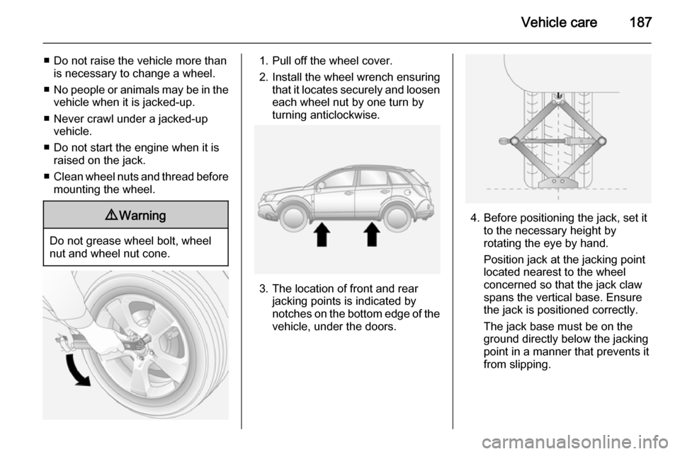
1. Pull off the wheel cover.
2. Install the wheel wrench ensuring that it locates securely and loosen
each wheel nut by one turn by
turning anticlockwise.
3. The location of front and rear jacking points is indicated by
notches on the bottom edge of the
vehicle, under the doors.
4. Before positioning the jack, set it to the necessary height by
rotating the eye by hand.
Position jack at the jacking point
located nearest to the wheel
concerned so that the jack claw
spans the vertical base. Ensure
the jack is positioned correctly.
The jack base must be on the
ground directly below the jacking
point in a manner that prevents it
from slipping.