warning VAUXHALL ANTARA 2015 Owner's Guide
[x] Cancel search | Manufacturer: VAUXHALL, Model Year: 2015, Model line: ANTARA, Model: VAUXHALL ANTARA 2015Pages: 223, PDF Size: 6.07 MB
Page 70 of 223

68Storage
Raise the release lever and hold. Liftthe system slightly and push it into the
bumper until it engages.
Release lever must return to original
position.9 Warning
If the system cannot be correctly
engaged, please seek the
assistance of a workshop.
Load compartment
Storage compartments in the
load compartment
Located on both sides of the load
compartment floor.
Load compartment cover Do not place any objects on the cover.
Closing the cover
Pull load compartment cover towards rear of vehicle using handle and insert
retainers into brackets on either side
of load compartment.
Opening the cover
Remove load compartment cover
from side brackets. The cover rolls up automatically.
Page 72 of 223
70Storage
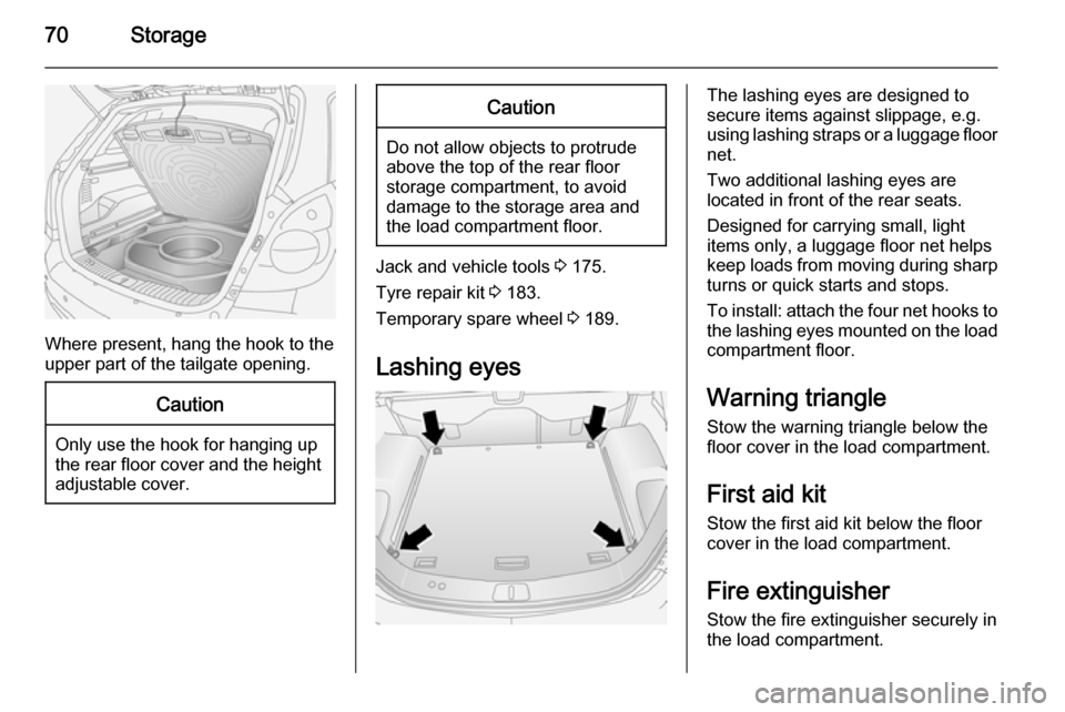
Where present, hang the hook to the
upper part of the tailgate opening.
Caution
Only use the hook for hanging up
the rear floor cover and the height adjustable cover.
Caution
Do not allow objects to protrude
above the top of the rear floor
storage compartment, to avoid
damage to the storage area and
the load compartment floor.
Jack and vehicle tools 3 175.
Tyre repair kit 3 183.
Temporary spare wheel 3 189.
Lashing eyes
The lashing eyes are designed to
secure items against slippage, e.g.
using lashing straps or a luggage floor
net.
Two additional lashing eyes are
located in front of the rear seats.
Designed for carrying small, light
items only, a luggage floor net helps keep loads from moving during sharp turns or quick starts and stops.
To install: attach the four net hooks to
the lashing eyes mounted on the load
compartment floor.
Warning triangle Stow the warning triangle below the
floor cover in the load compartment.
First aid kit Stow the first aid kit below the floor
cover in the load compartment.
Fire extinguisher
Stow the fire extinguisher securely in
the load compartment.
Page 73 of 223

Storage71Roof rack system
Roof rack For safety reasons and to avoiddamage to the roof, the vehicle
approved roof rack system is
recommended. For further
information contact a workshop.
Fasten the roof rack to the roof rails following the instructions that
accompany the system, ensuring that
the roof load is evenly distributed over the side or cross rails.
Loads must not be placed on the roof
surface. To prevent damage or loss,
check frequently that roof loads are
securely fastened.
Driving with a roof load affects the
vehicle centre of gravity; drive
carefully in crosswinds and do not
drive at high speeds.
Remove the roof rack when not in use.Loading information
■ Heavy objects in the load compartment should be evenly
distributed and placed as far
forward as possible. Ensure the
backrests are securely engaged. If
objects can be stacked, the heavier
objects should be placed at the bottom.
With rear seats in the folded
position, objects must not be
stacked higher than the seat
backrests.
■ Secure objects with lashing straps attached to lashing eyes 3 70.
■ Secure loose objects in the load compartment, e.g. with a luggage
floor net, to prevent sliding.
■ When transporting objects in the load compartment, the backrests ofthe rear seats must not be angled
forward.
■ Do not allow the load to protrude above the upper edge of the
backrests.■ Do not place any objects on the load compartment cover or the
instrument panel, and do not cover
the sensor on top of the instrument
panel.
■ The load must not obstruct the operation of the pedals, electrical
parking brake and gear selector, or hinder the freedom of movement ofthe driver. Do not place any
unsecured objects in the interior.
■ Do not drive with an open load compartment.9 Warning
Always make sure that the load in
the vehicle is securely stowed.
Otherwise objects can be thrown
around inside the vehicle and
cause personal injury or damage
to the load or vehicle.
■ The payload is the difference between the permitted gross
vehicle weight (see identification
plate 3 201) and the EC kerb
weight.
Page 75 of 223
Instruments and controls73Instruments and
controlsControls ....................................... 73
Warning lights, gauges and indi‐ cators ........................................... 80
Information displays .....................92
Vehicle messages ...................... 100
Trip computer ............................. 101Controls
Steering wheel adjustment
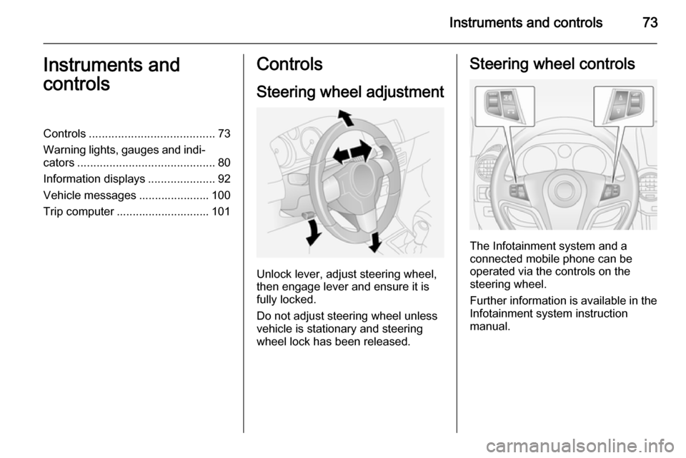
Unlock lever, adjust steering wheel,
then engage lever and ensure it is fully locked.
Do not adjust steering wheel unless
vehicle is stationary and steering
wheel lock has been released.
Steering wheel controls
The Infotainment system and a
connected mobile phone can be
operated via the controls on the
steering wheel.
Further information is available in the
Infotainment system instruction
manual.
Page 78 of 223
76Instruments and controls
Control indicator G illuminates in the
instrument cluster when the washer
fluid level is low.
Wiper activated lighting
With light switch in the AUTO
position, when the windscreen wiper
is operated for 8 cycles or more the
exterior lights illuminate
automatically.
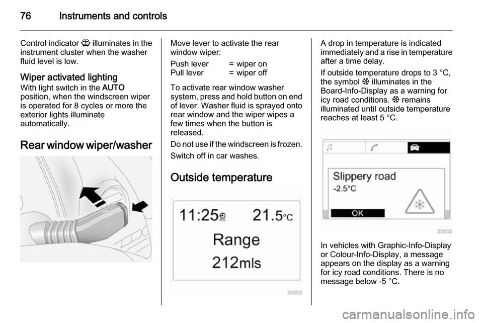
Rear window wiper/washerMove lever to activate the rear
window wiper:Push lever=wiper onPull lever=wiper off
To activate rear window washer
system, press and hold button on end
of lever. Washer fluid is sprayed onto rear window and the wiper wipes a
few times when the button is
released.
Do not use if the windscreen is frozen.
Switch off in car washes.
Outside temperature
A drop in temperature is indicated
immediately and a rise in temperature
after a time delay.
If outside temperature drops to 3 °C, the symbol : illuminates in the
Board-Info-Display as a warning for
icy road conditions. : remains
illuminated until outside temperature
reaches at least 5 °C.
In vehicles with Graphic-Info-Display
or Colour-Info-Display, a message
appears on the display as a warning for icy road conditions. There is no
message below -5 °C.
Page 79 of 223
Instruments and controls779Warning
The road surface may already be
icy even though the display
indicates a few degrees above 0
°C.
Clock
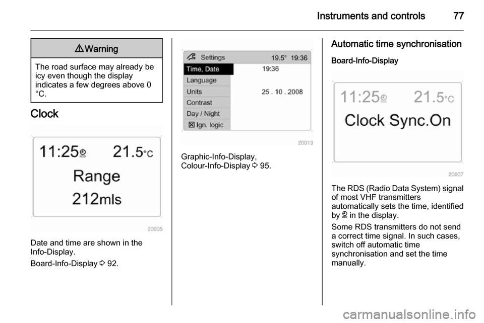
Date and time are shown in the
Info-Display.
Board-Info-Display 3 92.
Graphic-Info-Display,
Colour-Info-Display 3 95.
Automatic time synchronisation
Board-Info-Display
The RDS (Radio Data System) signal of most VHF transmitters
automatically sets the time, identified
by } in the display.
Some RDS transmitters do not send
a correct time signal. In such cases,
switch off automatic time
synchronisation and set the time
manually.
Page 82 of 223
80Instruments and controlsWarning lights, gauges
and indicators
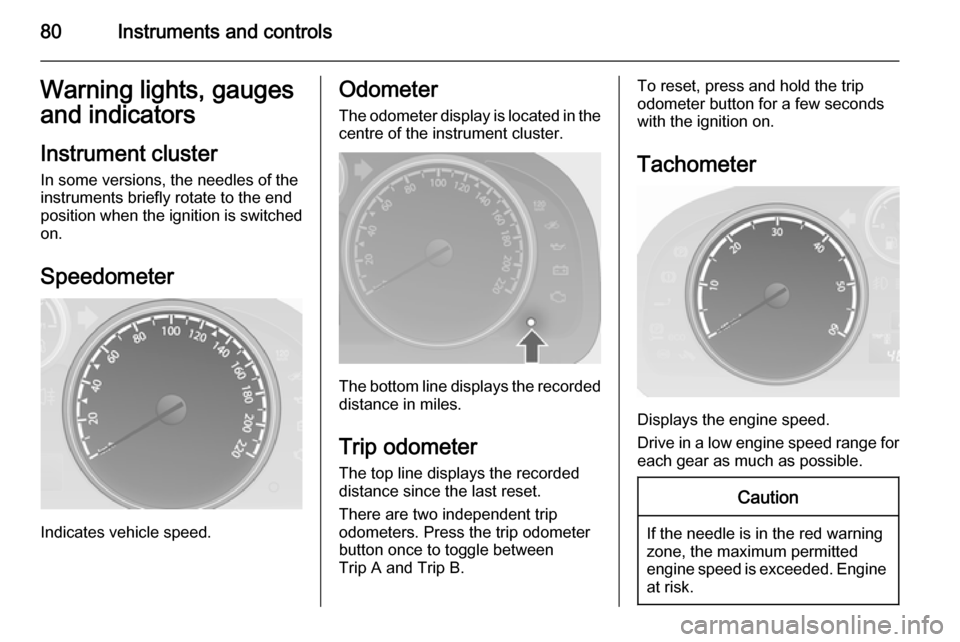
Instrument cluster In some versions, the needles of the
instruments briefly rotate to the end
position when the ignition is switched
on.
Speedometer
Indicates vehicle speed.
Odometer
The odometer display is located in the centre of the instrument cluster.
The bottom line displays the recordeddistance in miles.
Trip odometer The top line displays the recorded
distance since the last reset.
There are two independent trip
odometers. Press the trip odometer
button once to toggle between
Trip A and Trip B.
To reset, press and hold the trip
odometer button for a few seconds
with the ignition on.
Tachometer
Displays the engine speed.
Drive in a low engine speed range for each gear as much as possible.
Caution
If the needle is in the red warning
zone, the maximum permitted
engine speed is exceeded. Engine at risk.
Page 83 of 223
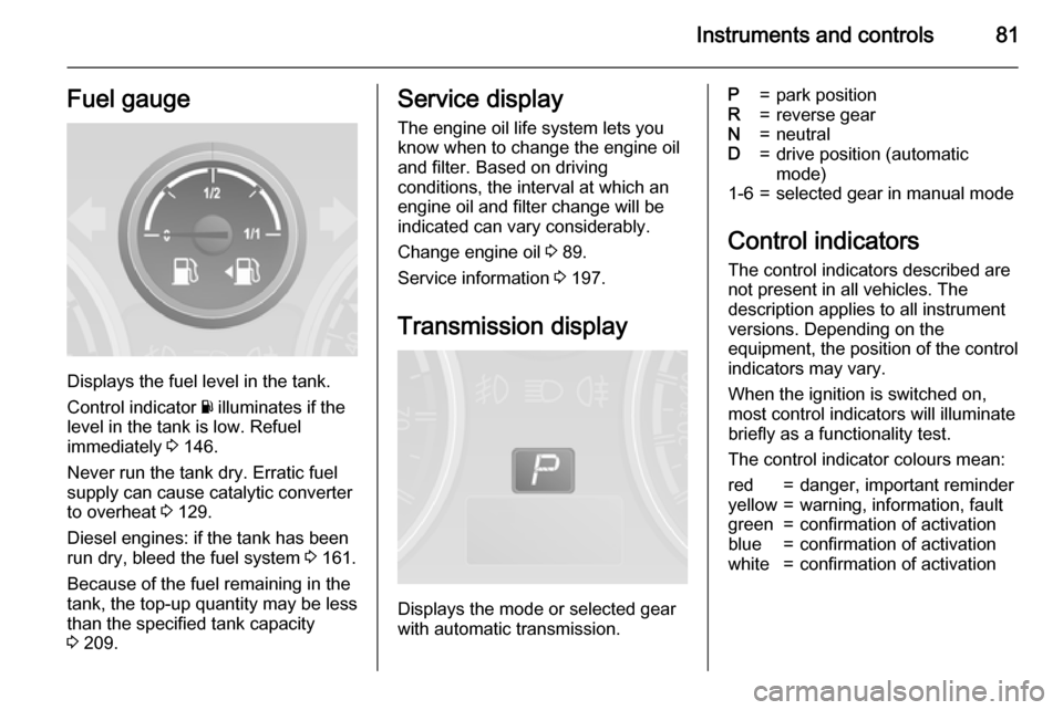
Instruments and controls81Fuel gauge
Displays the fuel level in the tank.
Control indicator Y illuminates if the
level in the tank is low. Refuel
immediately 3 146.
Never run the tank dry. Erratic fuel
supply can cause catalytic converter
to overheat 3 129.
Diesel engines: if the tank has been
run dry, bleed the fuel system 3 161.
Because of the fuel remaining in the
tank, the top-up quantity may be less
than the specified tank capacity
3 209.
Service display
The engine oil life system lets you
know when to change the engine oil
and filter. Based on driving
conditions, the interval at which an
engine oil and filter change will be
indicated can vary considerably.
Change engine oil 3 89.
Service information 3 197.
Transmission display
Displays the mode or selected gear
with automatic transmission.
P=park positionR=reverse gearN=neutralD=drive position (automatic
mode)1-6=selected gear in manual mode
Control indicators
The control indicators described are
not present in all vehicles. The
description applies to all instrument
versions. Depending on the
equipment, the position of the control
indicators may vary.
When the ignition is switched on,
most control indicators will illuminate
briefly as a functionality test.
The control indicator colours mean:
red=danger, important reminderyellow=warning, information, faultgreen=confirmation of activationblue=confirmation of activationwhite=confirmation of activation
Page 86 of 223

84Instruments and controlsTurn signal
O illuminates or flashes green.
The relevant control indicator flashes
when the turn signal is switched on
3 109.
Rapid flashing: failure of a turn signal bulb or the associated fuse or failure
of a turn signal light on trailer.
Both control indicators flash when the
hazard warning flashers are active
3 108.
Bulb replacement 3 161, Fuses
3 167.
Turn signals 3 109.
Seat belt reminder Seat belt reminder for front
seats X for driver's seat illuminates or
flashes red.
k for front passenger's seat
illuminates or flashes red, when the
seat is occupied.When the engine is running, if seat
belt is not engaged, the control
indicator will flash for 100 seconds
then illuminate until seat belt is
fastened.
If vehicle speed exceeds 14 mph, the
control indicator will flash for
100 seconds along with a warning
chime and remains illuminated until seat belt is fastened.
Fastening the seat belt 3 41.
Front passenger seat belt reminder k
3 42.
Airbag and belt tensioners v illuminates red.
When the ignition is switched on, v
flashes briefly. If it does not flash,
stays lit or flashes during driving,
there is a fault in the airbag system.
Seek the assistance of a workshop.
The airbags and belt pretensioners
may fail to trigger in the event of an
accident.
Deployment of the belt pretensioners
or airbags is indicated by continuous
illumination of v.9
Warning
Have the cause of the fault
remedied immediately by a
workshop.
Belt pretensioners, airbag system
3 41, 3 44.
Charging system
p illuminates red.
Illuminates when the ignition is
switched on and extinguishes shortly
after the engine starts. If it does not
illuminate, seek the assistance of a
workshop.
Illuminates when the engine is running
Stop vehicle and switch off engine.
Battery is not charging. Engine
cooling may be interrupted. The
brake servo unit may cease to be
effective.
Page 87 of 223

Instruments and controls85
Interrupt your journey immediately.Remove key and check drive belt
condition and tensioning before
seeking the assistance of a
workshop.
Malfunction indicator light Z illuminates or flashes yellow.
Illuminates when the ignition is
switched on and extinguishes shortly
after the engine starts. If it does not
illuminate, seek the assistance of a
workshop.
Can illuminate briefly when driving;
this is normal and does not indicate a
system fault.
Illuminates when the engine is
running
Fault in the emission control system.
The permitted emission limits may be exceeded. Fuel economy and vehicle
driveability may be impaired. Seek
the assistance of a workshop
immediately.Control indicator Z also illuminates if
there is a fault in the diesel particle
filter 3 128 or with the automatic
transmission 3 133. Seek the
assistance of a workshop as soon as
possible.
Ensure the fuel filler cap is screwed in completely 3 146.
Flashes when the engine is
running
Fault that could lead to catalytic
converter damage 3 129 . Ease up on
the accelerator until the flashing
stops. Seek the assistance of a
workshop immediately.
Service vehicle soon g illuminates yellow.
Illuminates when the engine is
running to indicate a fault in the
engine or transmission electronics. The electronics switch to an
emergency running programme, fuel
consumption may be increased and
vehicle handling may be impaired.In some cases, the fault can be
eliminated by switching the engine off
and back on again. If g illuminates
again after restarting the engine, the vehicle may need a service.
Have the cause of the fault eliminated by a workshop.
Brake system
R illuminates red.
Illuminates when the ignition is
switched on and extinguishes shortly
after the engine starts. If it does not
illuminate, stop and seek the
assistance of a workshop.
If it stays lit while the engine is
running, the brakes do not operate as normal, or leaks are found in the
brake system, do not attempt to drive
the vehicle. Have the vehicle towed to a workshop for inspection and repair.9 Warning
Stop. Do not continue your
journey. Consult a workshop.