engine VAUXHALL ANTARA 2015 Repair Manual
[x] Cancel search | Manufacturer: VAUXHALL, Model Year: 2015, Model line: ANTARA, Model: VAUXHALL ANTARA 2015Pages: 223, PDF Size: 6.07 MB
Page 173 of 223

Vehicle care171
FuseCircuitABSAnti-lock Brake
SystemA/CClimate control,
air conditioning
systemBATT1Instrument panel
fuse boxBATT2Instrument panel
fuse boxBATT3Instrument panel
fuse boxBCMBody Control
ModuleECMEngine Control
ModuleECM PWR TRNEngine Control
Module, Power‐
trainENG SNSREngine sensorsEPBElectrical parking
brakeFuseCircuitFAN1Cooling fanFAN3Cooling fanFRT FOGFront fog lightsFRT WPRFront wiperFUEL/VACFuel pump,
vacuum pumpHDLP WASHERHeadlight washerHI BEAM LHHigh beam (left-
hand)HI BEAM RHHigh beam (right-
hand)HORNHornHTD WASH/MIRHeated washer
fluid, heated exte‐
rior mirrorsIGN COIL AIgnition coilIGN COIL BIgnition coilLO BEAM LHLow beam (left-
hand)FuseCircuitLO BEAM RHLow beam (right-
hand)PRK LP LHParking light (left-
hand)PRK LP RHParking light
(right-hand)PWM FANPulse width modu‐ lation fanREAR DEFOGHeated rear
windowREAR WPRRear wiperSPARE–STOP LAMPBrake lightsSTRTRStarterTCMTransmission
Control ModuleTRLR PRL LPTrailer parking
lights
Page 180 of 223

178Vehicle care
V=up to 150 mphW=up to 168 mph
Tyre pressureCheck the pressure of cold tyres at
least every 14 days and before any
long journey. Do not forget the spare
wheel. This also applies to vehicles
with tyre pressure monitoring system.
Use the valve cap key to make
unscrewing the valve caps easier.
The valve cap key is located on the
inside of the tank flap.
Tyre pressure 3 210.
The tyre pressure data refers to cold
tyres. It applies to summer and winter tyres.
Always inflate the spare tyre to the
pressure specified for full load.
The ECO tyre pressure serves to
achieve the smallest amount of fuel
consumption possible.
Incorrect tyre pressures will impair
safety, vehicle handling, comfort and
fuel economy and will increase tyre
wear.
Tyre pressures differ depending on
various options. For the correct tyre
pressure value, follow the procedure
below:
1. Identify the engine identifier code.
Engine data 3 205.
2. Identify the respective tyre.
The tyre pressure tables show all
possible tyre combinations 3 210.
For the tyres approved for your
vehicle, refer to the EEC Certificate of Conformity provided with your vehicle
or other national registration
documents.
The driver is responsible for correct
adjustment of tyre pressure.9 Warning
If the pressure is too low, this can
result in considerable tyre warm-
up and internal damage, leading to tread separation and even to tyre
blow-out at high speeds.
If the tyre pressure must be reduced
or increased on a vehicle with tyre
pressure monitoring system, switch
off ignition.
Tyre pressure monitoring system The tyre pressure monitoring system
checks the pressure of all four wheels
once per minute when vehicle speed
exceeds a certain limit.Caution
Tyre pressure monitoring system
warns only about low tyre pressure
condition and does not replace
regular tyre maintenance by the
driver.
All wheels must be equipped with pressure sensors and the tyres must
have the prescribed pressure. If
wheels without sensors are mounted,
the tyre pressure monitoring system
is not operational.
Page 186 of 223

184Vehicle care
Pull the floor cover handle upwards
3 69.
Vehicle tools 3 175.Caution
Do not allow objects to protrude
above the top of the rear floor
storage compartment, to avoid
damage to the storage area and
the load compartment floor.
1. Release the sealant filler hose 1
and the power plug 2.
2. Unscrew valve cap from defective
tyre.
Screw the sealant filler hose onto
the tyre valve.
3. Connect the power plug to the power outlet. Unplug all items
from other power outlets.
4. Switch on ignition. To avoid discharging the battery, werecommend running the engine.
5. Turn the selector switch anticlockwise to the sealant +
air position.
6. Press the on/off button to turn the
tyre repair kit on. The tyre is filled
with sealant.
The pressure gauge briefly shows a high pressure while the sealant
canister is emptying. Then the
pressure starts to drop.
All of the sealant is pumped into
the tyre. Then the tyre is inflated.
7. Inflate the tyre to the recommended inflation pressure
using the pressure gauge. The
prescribed tyre pressure should
be obtained within 10 minutes
3 210 . When the correct pressure
Page 189 of 223

Vehicle care187
■ Do not raise the vehicle more thanis necessary to change a wheel.
■ No people or animals may be in the
vehicle when it is jacked-up.
■ Never crawl under a jacked-up vehicle.
■ Do not start the engine when it is raised on the jack.
■ Clean wheel nuts and thread before
mounting the wheel.9 Warning
Do not grease wheel bolt, wheel
nut and wheel nut cone.
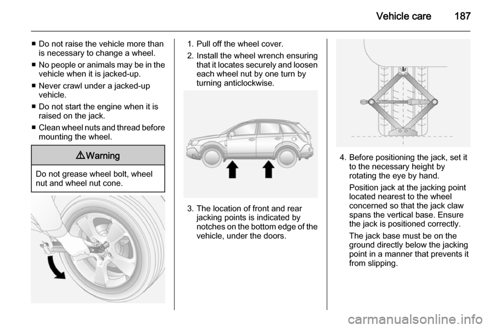
1. Pull off the wheel cover.
2. Install the wheel wrench ensuring that it locates securely and loosen
each wheel nut by one turn by
turning anticlockwise.
3. The location of front and rear jacking points is indicated by
notches on the bottom edge of the
vehicle, under the doors.
4. Before positioning the jack, set it to the necessary height by
rotating the eye by hand.
Position jack at the jacking point
located nearest to the wheel
concerned so that the jack claw
spans the vertical base. Ensure
the jack is positioned correctly.
The jack base must be on the
ground directly below the jacking
point in a manner that prevents it
from slipping.
Page 193 of 223

Vehicle care191
■ A discharged battery can alreadyfreeze at a temperature of 0 °C.
Defrost the frozen battery before
connecting jump leads.
■ Wear eye protection and protective
clothing when handling a battery.
■ Use a booster battery with the same voltage (12 Volts). Its
capacity (Ah) must not be much less than that of the discharged
battery.
■ Use jump leads with insulated terminals and a cross section of at
least 16 mm 2
(25 mm 2
for diesel
engines).
■ Do not disconnect the discharged battery from the vehicle.
■ Switch off all unnecessary electrical
consumers. The Infotainment
system may be damaged if
switched on while jump starting.
■ Do not lean over the battery during jump starting.
■ Do not allow the terminals of one lead to touch those of the other
lead.■ The vehicles must not come into contact with each other during the
jump starting process.
■ Apply the electrical parking brake 3 137, transmission in neutral,
automatic transmission in P.
■ Open the positive terminal protection caps of both batteries.
Lead connection order:
1. Connect the red lead to the positive terminal 1 of the booster
battery.
2. Connect the other end of the red lead to the positive terminal 2 of
the discharged battery.
3. Connect the black lead to the negative terminal 3 of the booster
battery.
4. Connect the other end of the black
lead to a vehicle grounding point,
such as the engine block 4 or an
engine mounting bolt. Connect as far away from the discharged
battery as possible, however at
least 60 cm.
Route the leads so that they cannot
catch on rotating parts in the engine
compartment.
To start the engine: 1. Start the engine of the vehicle providing the jump start.
2. After 5 minutes, start the other engine. Start attempts should be
made for no longer than
15 seconds at an interval of
1 minute.
3. Allow both engines to idle for approx. 3 minutes with the leads
connected.
Page 195 of 223

Vehicle care193
Turn key to ignition switch position
ACC and release the electrical
parking brake before towing the
vehicle.Caution
Drive slowly. Do not drive jerkily.
Excessive tractive force can
damage the vehicle.
When the engine is not running,
considerably more force is needed to
brake and steer.
Keep tow rope clear of front bumper, and ensure it is securely fixed to the
towing eye at both ends. Pull on the tow rope to check.
To prevent the entry of exhaust gases from the towing vehicle, switch on the
air recirculation system 3 116 and
close the windows.
Vehicles with manual transmission:
The vehicle must be towed facing
forwards. The maximum speed is
55 mph. In all other cases, and when
the transmission is defective, the front axle must be raised off the ground.
Vehicles with automatic transmission:
Do not tow the vehicle using the
towing eye. Towing with a tow rope
could cause severe damage to the
transmission. When towing a vehicle
with automatic transmission, use flat
bed or wheel lift equipment.
Seek the assistance of a workshop.
After towing, unscrew the towing eye
and replace the spoiler lip. Store
towing eye in the storage
compartment below the floor cover in the load compartment.
Vehicle tools 3 175.Towing another vehicle
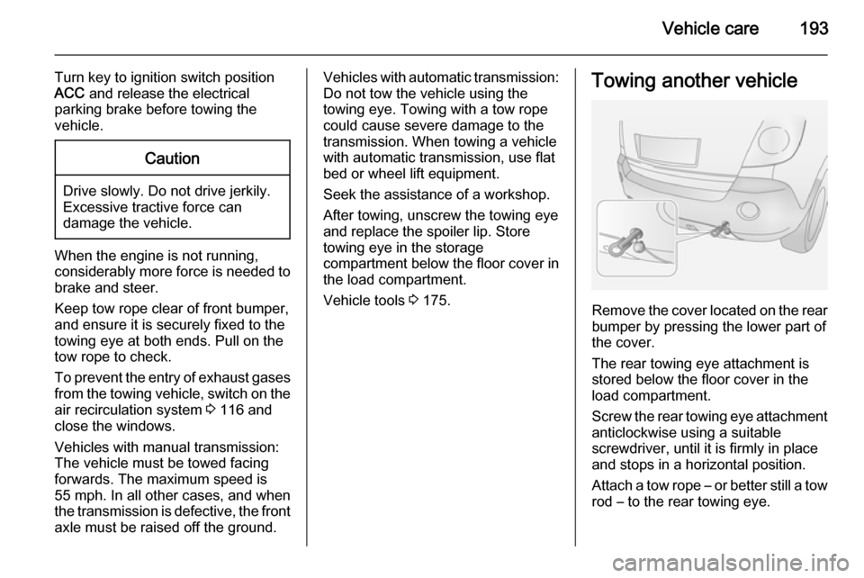
Remove the cover located on the rear
bumper by pressing the lower part of
the cover.
The rear towing eye attachment is
stored below the floor cover in the
load compartment.
Screw the rear towing eye attachment
anticlockwise using a suitable
screwdriver, until it is firmly in place
and stops in a horizontal position.
Attach a tow rope – or better still a tow
rod – to the rear towing eye.
Page 196 of 223

194Vehicle care
The towing eye must only be used fortowing and not for recovering a
vehicle.Caution
Drive slowly. Do not drive jerkily.
Excessive tractive force can
damage the vehicle.
To prevent damage, do not take up slack in the tow rope too quickly.
After towing, unscrew the rear towing
eye attachment clockwise to remove,
and reinstall the cover.
Appearance care
Exterior care Locks
The locks are lubricated at the factory using a high quality lock cylinder
grease. Use de-icing agent only when absolutely necessary, as this has adegreasing effect and impairs lockfunction. After using a de-icing agent,
have the locks regreased by a
workshop.
Washing The paintwork of your vehicle is
exposed to environmental influences.
Wash and wax your vehicle regularly.
When using automatic car washes,
select a programme that includes waxing.
Bird droppings, dead insects, resin,
pollen and the like should be cleaned
off immediately, as they contain
aggressive constituents which can
cause paint damage.If using a car wash, comply with the
car wash manufacturer's instructions.
The windscreen wiper and rear
window wiper must be switched off.
Remove antenna and external
accessories such as roof racks etc.
If you wash your vehicle by hand,
make sure that the insides of the
wheel housings are also thoroughly
rinsed out.
Clean edges and folds on opened
doors and the bonnet as well as the
areas they cover.Caution
Always use a cleaning agent with
a pH value of 4 to 9.
Do not use cleaning agents on hot surfaces.
Have the door hinges of all doors
greased by a workshop.
Do not clean the engine compartment with a steam-jet or high-pressure jet
cleaner.
Page 200 of 223

198Service and maintenance
Confirmations
Confirmation of service is recorded in the Service and Warranty Booklet.The date and mileage is completed
with the stamp and signature of the servicing workshop.
Make sure that the Service and
Warranty Booklet is completed
correctly as continuous proof of
service is essential if any warranty or goodwill claims are to be met, and is
also a benefit when selling the
vehicle.
Service interval with remaining engine oil life duration The service interval is based on
several parameters depending on
usage.
The service display lets you know
when to change the engine oil.
Service display 3 81.Recommended fluids,
lubricants and parts
Recommended fluids and
lubricants Only use products that meet the
recommended specifications.
Damage resulting from the use of
products not in line with these
specifications will not be covered by
the warranty.9 Warning
Operating materials are
hazardous and could be
poisonous. Handle with care. Pay
attention to information given on
the containers.
Engine oil
Engine oil is identified by its quality
and its viscosity. Quality is more
important than viscosity when
selecting which engine oil to use. The oil quality ensures e.g. engine
cleanliness, wear protection and oil
ageing control, whereas viscosity
grade gives information on the oil's
thickness over a temperature range.
Dexos is the newest engine oil quality
that provides optimum protection for gasoline and diesel engines. If it is
unavailable, engine oils of other listed qualities have to be used.
Recommendations for petrol engines
are also valid for Ethanol (E85)
fuelled engines.
Select the appropriate engine oil
based on its quality and on the
minimum ambient temperature
3 202.
Topping up engine oil
Engine oils of different manufacturers
and brands can be mixed as long as
they comply with the required engine
oil quality and viscosity.
Use of engine oil with only
ACEA A1/B1 or only A5/B5 quality is
prohibited, since it can cause long-
term engine damage under certain
operating conditions.
Page 201 of 223

Service and maintenance199
Select the appropriate engine oil
based on its quality and on the
minimum ambient temperature
3 202.
Additional engine oil additives
The use of additional engine oil
additives could cause damage and
invalidate the warranty.
Engine oil viscosity
The SAE viscosity grade gives
information of the thickness of the oil.
Multigrade oil is indicated by two
figures, e.g. SAE 5W-30. The first
figure, followed by a W, indicates the
low temperature viscosity and the
second figure the high temperature viscosity.
Select the appropriate viscosity grade depending on the minimum ambient
temperature 3 202.
All of the recommended viscosity
grades are suitable for high ambient
temperatures.Coolant and antifreeze
Use only silicate-free long life coolant (LLC) antifreeze. Consult a
workshop.
The system is factory filled with
coolant designed for excellent
corrosion protection and frost
protection down to approx. -28 °C. In
northern countries with very low
temperatures the factory filled coolant
provides frost protection down to
approx. -37 °C. This concentration
should be maintained all year round.
The use of additional coolant
additives that intend to give additional
corrosion protection or seal against
minor leaks can cause function
problems. Liability for consequences
resulting from the use of additional coolant additives will be rejected.
Brake and clutch fluid Over time, brake fluid absorbs
moisture which will reduce braking
effectiveness. The brake fluid should
therefore be replaced at the specified
interval.
Page 202 of 223

200Technical dataTechnical dataVehicle identification..................200
Vehicle data ............................... 202Vehicle identification
Vehicle Identification
Number
The Vehicle Identification Number is
visible through the windscreen.
The Vehicle Identification Number is
also engraved on the top right-hand
side of the bulkhead near the centre
of the engine firewall.