clock VAUXHALL ANTARA 2015 Owner's Manual
[x] Cancel search | Manufacturer: VAUXHALL, Model Year: 2015, Model line: ANTARA, Model: VAUXHALL ANTARA 2015Pages: 223, PDF Size: 6.07 MB
Page 79 of 223
Instruments and controls779Warning
The road surface may already be
icy even though the display
indicates a few degrees above 0
°C.
Clock
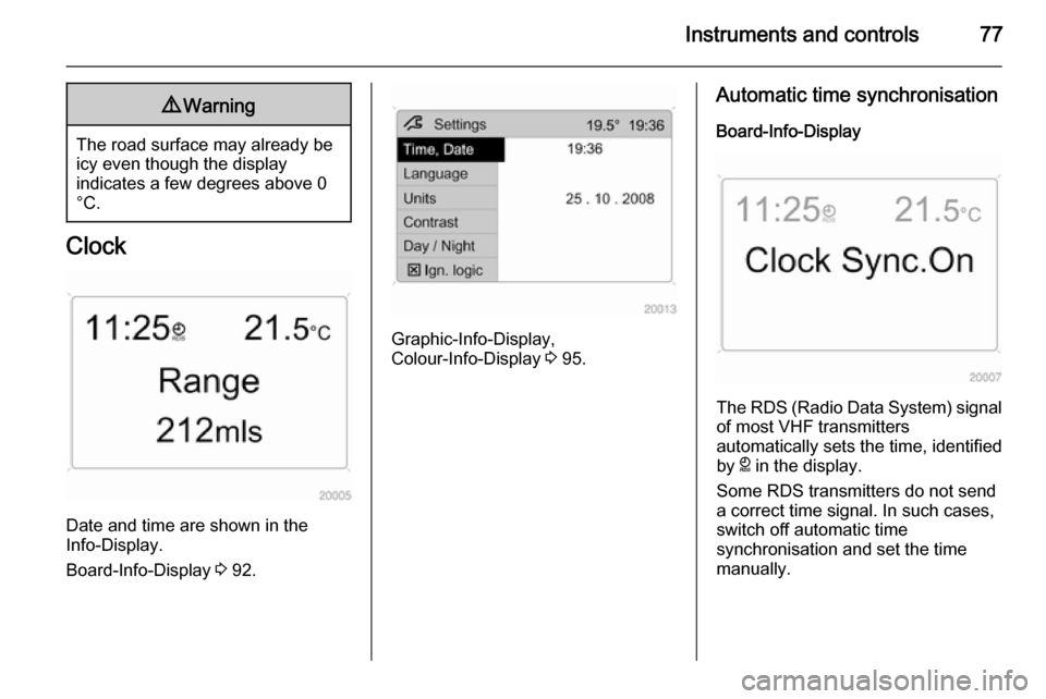
Date and time are shown in the
Info-Display.
Board-Info-Display 3 92.
Graphic-Info-Display,
Colour-Info-Display 3 95.
Automatic time synchronisation
Board-Info-Display
The RDS (Radio Data System) signal of most VHF transmitters
automatically sets the time, identified
by } in the display.
Some RDS transmitters do not send
a correct time signal. In such cases,
switch off automatic time
synchronisation and set the time
manually.
Page 80 of 223
78Instruments and controls
Deactivate (Clock Sync.Off ) or
activate ( Clock Sync.On ) automatic
time synchronisation with the arrow buttons on the Infotainment system.
To set date and time manually, select
the menu item for time and date
setting from the Settings menu and
make the desired setting. The value
ready for modification is marked with
arrows. Use the arrow buttons to
make the required setting. The setting
is saved when the menu item is
exited.
To correct time with the help of RDS,
select the menu item for time
synchronisation from the Settings
menu and make the desired setting.
Board-Info-Display 3 92.Graphic-Info-Display, Colour-Info-
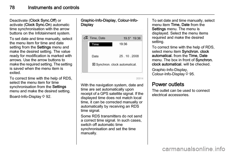
Display
With the navigation system, date and
time are set automatically upon
receipt of a GPS satellite signal. If the
displayed time does not match local
time, it can be corrected manually or
automatically by receiving an RDS
time signal.
Some RDS transmitters do not send a correct time signal. In such cases,
switch off automatic time
synchronisation and set the time
manually.
To set date and time manually, select
menu item Time, Date from the
Settings menu. The menu is
displayed. Select the menu items
required and make the desired
setting.
To correct time with the help of RDS,
select menu item Synchron. clock
automatical. from the Time, Date
menu. The box in front of Synchron.
clock automatical. will be checked.
Graphic-Info-Display,
Colour-Info-Display 3 95.
Power outlets
The outlet can be used to connect
electrical accessories.
Page 96 of 223
94Instruments and controls
■ Time, setting minutes
■ Date, setting day
■ Date, setting month
■ Date, setting year
■ Ignition logic
■ Language selection
■ Setting units of measure
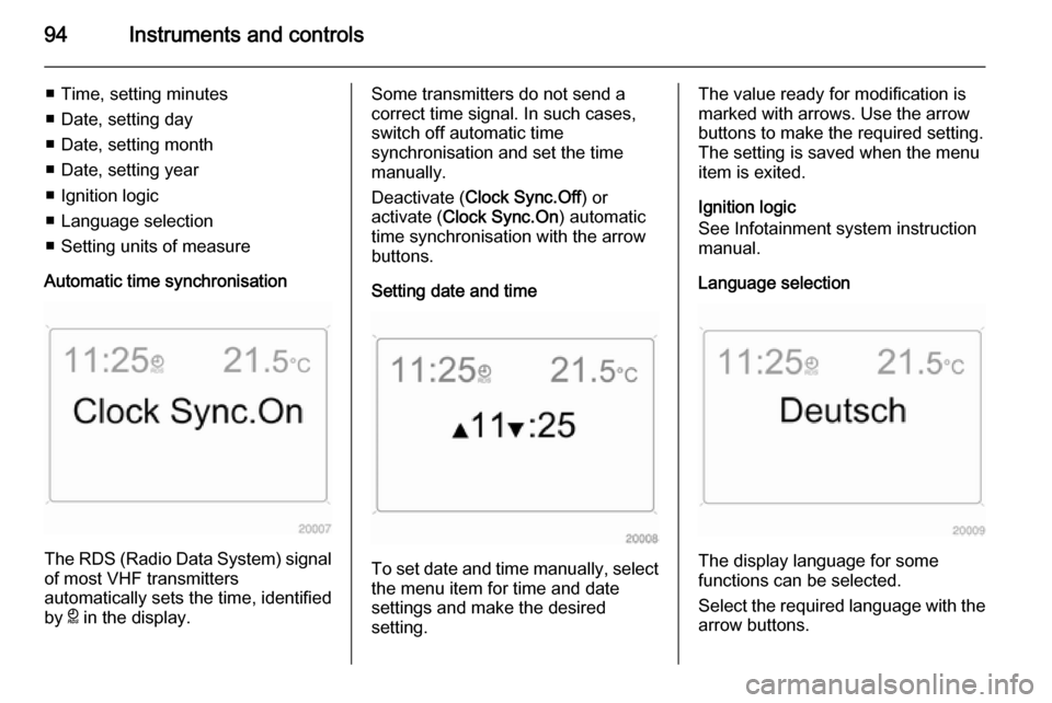
Automatic time synchronisation
The RDS (Radio Data System) signal of most VHF transmitters
automatically sets the time, identified
by } in the display.
Some transmitters do not send a
correct time signal. In such cases,
switch off automatic time
synchronisation and set the time
manually.
Deactivate ( Clock Sync.Off ) or
activate ( Clock Sync.On ) automatic
time synchronisation with the arrow
buttons.
Setting date and time
To set date and time manually, select
the menu item for time and date
settings and make the desired
setting.
The value ready for modification is
marked with arrows. Use the arrow
buttons to make the required setting.
The setting is saved when the menu item is exited.
Ignition logic
See Infotainment system instruction
manual.
Language selection
The display language for some
functions can be selected.
Select the required language with the
arrow buttons.
Page 100 of 223
98Instruments and controls
Some RDS transmitters do not send
a correct time signal. In such cases,
switch off automatic time
synchronisation and set the time
manually.
To set date and time manually, select
menu item Time, Date from the
Settings menu. The menu is
displayed. Select the menu items
required and make the desired
setting.
To correct time with the help of RDS,
select menu item Synchron. clock
automatical. from the Time, Date
menu. The box in front of Synchron.
clock automatical. will be checked.Language selection
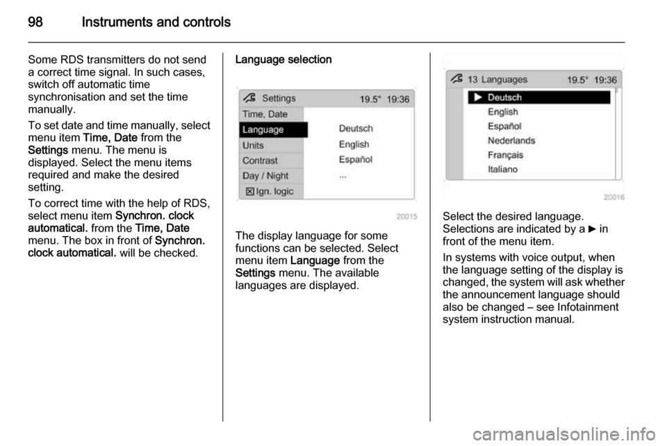
The display language for some
functions can be selected. Select
menu item Language from the
Settings menu. The available
languages are displayed.
Select the desired language.
Selections are indicated by a 6 in
front of the menu item.
In systems with voice output, when
the language setting of the display is
changed, the system will ask whether the announcement language should
also be changed – see Infotainment
system instruction manual.
Page 148 of 223

146Driving and operating
Do not use marine diesel oils, heating
oils, Aquazole and similar diesel-
water emulsions. Diesel fuels must
not be diluted with fuels for petrol
engines.
Refuelling9 Danger
Before refuelling, switch off engine
and any external heaters with
combustion chambers. Switch off
any mobile phones.
Follow the operating and safety
instructions of the filling station
when refuelling.
9 Danger
Fuel is flammable and explosive.
No smoking. No naked flames or
sparks.
If you can smell fuel in your
vehicle, have the cause of this
remedied immediately by a
workshop.
Caution
In case of misfuelling, do not
switch on ignition.
Fuel filler flap is located at left rear
side of vehicle.
The fuel filler flap can only be opened
if the vehicle is unlocked 3 21.
Release the fuel filler flap by pushing the flap.
To unlock fuel filler cap: turn it
anticlockwise. If hissing occurs, wait
until it stops before completely
unscrewing the cap.
The fuel filler cap can be retained in
the holder on the inside of the fuel
filler flap.
When refuelling, fully insert the pump nozzle and switch it on.
After the automatic cut-off, the fuel
tank can be topped up with a
maximum two doses of fuel.Caution
Wipe off any overflowing fuel
immediately.
After refuelling, replace the fuel filler
cap and turn it clockwise until you
hear several clicks. Ensure the cap is
screwed in completely, otherwise
control indicator Z may illuminate in
the instrument cluster 3 85.
Close fuel filler flap.
Fuel filler cap
Only a genuine fuel filler cap provides
full functionality. Diesel-engined
vehicles have special fuel filler caps.
Page 162 of 223

160Vehicle care
Charging the vehicle battery9Warning
On vehicles with stop-start
system, ensure that the charging potential does not exceed
14.6 volts when using a battery
charger. Otherwise the vehicle
battery might be damaged.
Jump starting 3 190.
Warning label
Meaning of symbols: ■ No sparks, naked flames or smoking.
■ Always shield eyes. Explosive gases can cause blindness or
injury.
■ Keep the vehicle battery out of reach of children.
■ The vehicle battery contains sulfuric acid which could cause
blindness or serious burn injuries.
■ See the Owner's Manual for further
information.
■ Explosive gas may be present in the vicinity of the vehicle battery.Diesel fuel filter
Drain diesel fuel filter of residual
water at every engine oil change.
Place a container underneath the
filter housing. Turn drain plug
anticlockwise using a suitable
screwdriver, to drain off the water.
The filter is drained as soon as diesel fuel emerges from the port. Retighten
the drain plug by turning it clockwise.
With engine switched off, turn ignition
key to ON, wait approx. 5 seconds,
and turn key to LOCK to perform
priming operation. Perform this
Page 165 of 223
Vehicle care163
5. Engage bulb retaining spring andreplace headlamp cap.
6. Reinstall headlamp assembly.
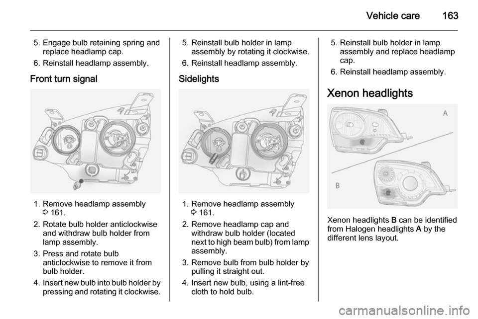
Front turn signal
1. Remove headlamp assembly 3 161.
2. Rotate bulb holder anticlockwise and withdraw bulb holder from
lamp assembly.
3. Press and rotate bulb anticlockwise to remove it from
bulb holder.
4. Insert new bulb into bulb holder by
pressing and rotating it clockwise.
5. Reinstall bulb holder in lamp assembly by rotating it clockwise.
6. Reinstall headlamp assembly.
Sidelights
1. Remove headlamp assembly 3 161.
2. Remove headlamp cap and withdraw bulb holder (located
next to high beam bulb) from lamp
assembly.
3. Remove bulb from bulb holder by pulling it straight out.
4. Insert new bulb, using a lint-free cloth to hold bulb.
5. Reinstall bulb holder in lampassembly and replace headlamp
cap.
6. Reinstall headlamp assembly.
Xenon headlights
Xenon headlights B can be identified
from Halogen headlights A by the
different lens layout.
Page 166 of 223
164Vehicle care
Low and high beam9Danger
Xenon headlights work under
extremely high electrical voltage.
Do not touch. Have bulbs replaced by a workshop.
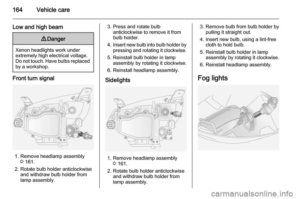
Front turn signal
1. Remove headlamp assembly 3 161.
2. Rotate bulb holder anticlockwise and withdraw bulb holder from
lamp assembly.
3. Press and rotate bulb anticlockwise to remove it from
bulb holder.
4. Insert new bulb into bulb holder by
pressing and rotating it clockwise.
5. Reinstall bulb holder in lamp assembly by rotating it clockwise.
6. Reinstall headlamp assembly.
Sidelights
1. Remove headlamp assembly 3 161.
2. Rotate bulb holder anticlockwise and withdraw bulb holder from
lamp assembly.
3. Remove bulb from bulb holder by pulling it straight out.
4. Insert new bulb, using a lint-free cloth to hold bulb.
5. Reinstall bulb holder in lamp assembly by rotating it clockwise.
6. Reinstall headlamp assembly.
Fog lights
Page 167 of 223
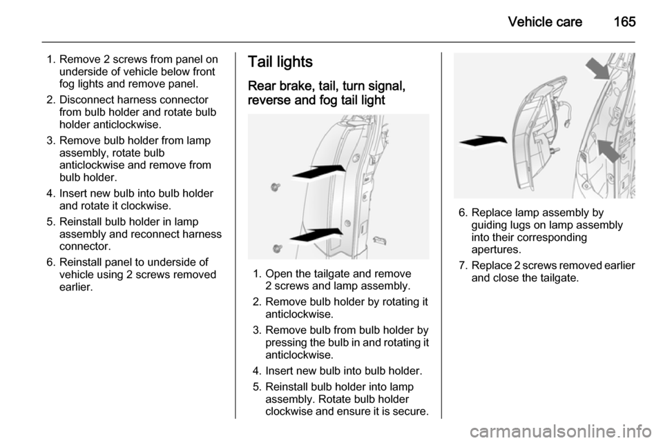
Vehicle care165
1. Remove 2 screws from panel onunderside of vehicle below front
fog lights and remove panel.
2. Disconnect harness connector from bulb holder and rotate bulb
holder anticlockwise.
3. Remove bulb holder from lamp assembly, rotate bulb
anticlockwise and remove from
bulb holder.
4. Insert new bulb into bulb holder and rotate it clockwise.
5. Reinstall bulb holder in lamp assembly and reconnect harnessconnector.
6. Reinstall panel to underside of vehicle using 2 screws removed
earlier.Tail lights
Rear brake, tail, turn signal,
reverse and fog tail light
1. Open the tailgate and remove 2 screws and lamp assembly.
2. Remove bulb holder by rotating it anticlockwise.
3. Remove bulb from bulb holder by pressing the bulb in and rotating it
anticlockwise.
4. Insert new bulb into bulb holder.
5. Reinstall bulb holder into lamp assembly. Rotate bulb holder
clockwise and ensure it is secure.
6. Replace lamp assembly by guiding lugs on lamp assembly
into their corresponding
apertures.
7. Replace 2 screws removed earlier
and close the tailgate.
Page 168 of 223
166Vehicle careSide turn signal lights
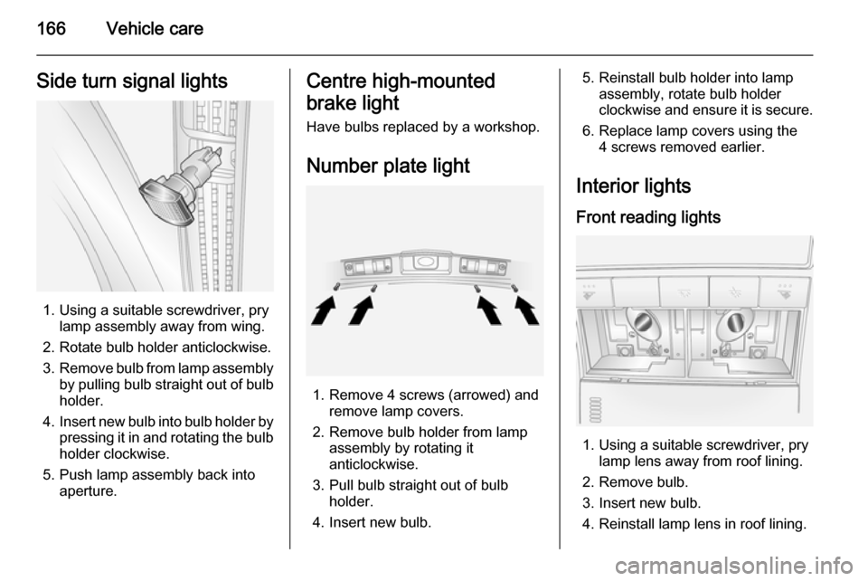
1. Using a suitable screwdriver, prylamp assembly away from wing.
2. Rotate bulb holder anticlockwise.
3. Remove bulb from lamp assembly
by pulling bulb straight out of bulb holder.
4. Insert new bulb into bulb holder by
pressing it in and rotating the bulb holder clockwise.
5. Push lamp assembly back into aperture.
Centre high-mounted
brake light Have bulbs replaced by a workshop.
Number plate light
1. Remove 4 screws (arrowed) and remove lamp covers.
2. Remove bulb holder from lamp assembly by rotating it
anticlockwise.
3. Pull bulb straight out of bulb holder.
4. Insert new bulb.
5. Reinstall bulb holder into lamp assembly, rotate bulb holder
clockwise and ensure it is secure.
6. Replace lamp covers using the 4 screws removed earlier.
Interior lights
Front reading lights
1. Using a suitable screwdriver, pry lamp lens away from roof lining.
2. Remove bulb.
3. Insert new bulb.
4. Reinstall lamp lens in roof lining.