steering VAUXHALL ASTRA J 2016.25 Service Manual
[x] Cancel search | Manufacturer: VAUXHALL, Model Year: 2016.25, Model line: ASTRA J, Model: VAUXHALL ASTRA J 2016.25Pages: 267, PDF Size: 7.72 MB
Page 192 of 267

190Driving and operatingTrailer hitch
General information
Only use towing equipment that has
been approved for your vehicle.
Entrust retrofitting of towing
equipment to a workshop. It may be
necessary to make changes that
affect the cooling system, heat
shields or other equipment.
The bulb outage detection function for trailer brake light cannot detect a
partial bulb outage, e.g. in case of four
times five watt bulbs, the function only detects lamp outage when only a
single five Watt lamp remains or none
remain.
Fitting of towing equipment could
cover the opening of the towing eye.
If this is the case use the coupling ball bar for towing. Always keep the
coupling ball bar in the vehicle when
not in use.Driving characteristics and
towing tips
Before attaching a trailer, lubricatethe coupling ball. However, do not do
so if a stabiliser, which acts on the
coupling ball, is being used to reduce snaking movements.
For trailers with low driving stability
and caravan trailers with a permitted
gross vehicle weight of more than
1300 kg the use of a stabiliser is
strongly recommended when driving
above 50 mph.
If the trailer starts snaking, drive more
slowly, do not attempt to correct the
steering and brake sharply if
necessary.
When driving downhill, drive in the
same gear as if driving uphill and
drive at a similar speed.
Adjust tyre pressure to the value
specified for full load 3 253.Trailer towing
Trailer loads
The permissible trailer loads are
vehicle and engine-dependent
maximum values which must not be
exceeded. The actual trailer load is
the difference between the actual
gross weight of the trailer and the
actual coupling socket load with the
trailer coupled.
The permissible trailer loads are
specified in the vehicle documents. In general, they are valid for gradients
up to max. 12%.
The permitted trailer load applies up to the specified incline and up to an
altitude of 1000 metres above sea
level. Since engine power decreases
as altitude increases due to the air becoming thinner, therefore reducing
climbing ability, the permissible gross
train weight also decreases by 10%
for every 1000 metres of additional
altitude. The gross train weight does
not have to be reduced when driving
on roads with slight inclines (less than 8%, e.g. motorways).
Page 195 of 267
Driving and operating193Attach breakaway stopping cable to
eye.
Check that the coupling ball bar is
correctly installed
● Green marking on rotary knob must point towards green
marking on coupling ball bar.
● There must be no gap between the rotary handle and the
coupling ball bar.
● The coupling ball bar must be firmly engaged in the opening.
● The coupling ball bar must be locked and the key removed.9Warning
Towing a trailer is permitted only
when a coupling ball bar is fitted correctly. If the coupling ball bardoes not engage correctly, seekthe assistance of a workshop.
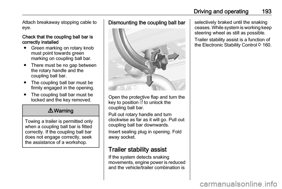
Dismounting the coupling ball bar
Open the protective flap and turn the
key to position c to unlock the
coupling ball bar.
Pull out rotary handle and turn
clockwise as far as it will go. Pull out coupling ball bar downwards.
Insert sealing plug in opening. Fold away socket.
Trailer stability assist
If the system detects snaking
movements, engine power is reduced
and the vehicle/trailer combination is
selectively braked until the snaking ceases. While system is working keep steering wheel as still as possible.
Trailer stability assist is a function of
the Electronic Stability Control 3 160.
Page 215 of 267
Vehicle care213No.Circuit46Instrument cluster47Steering column lock48Rear wiper49Heated mirror50LED headlight right/Automatic
headlight range adjustment
right51Left low beam (LED)52Engine control module/Trans‐
mission control module53–54Windscreen wiper55–56–57–
After having changed defective fuses,
close the fuse box cover and press
until it engages.
If the fuse box cover is not closed
correctly, malfunction may occur.
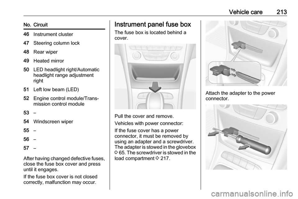
Instrument panel fuse box
The fuse box is located behind a
cover.
Pull the cover and remove.
Vehicles with power connector:
If the fuse cover has a power
connector, it must be removed by
using an adapter and a screwdriver.
The adapter is stowed in the glovebox 3 65 . The screwdriver is stowed in the
load compartment 3 217.
Attach the adapter to the power
connector.
Page 216 of 267
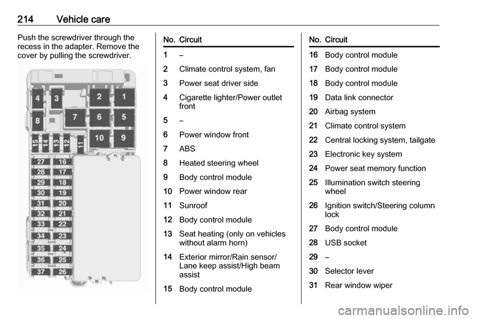
214Vehicle carePush the screwdriver through therecess in the adapter. Remove the
cover by pulling the screwdriver.No.Circuit1–2Climate control system, fan3Power seat driver side4Cigarette lighter/Power outlet
front5–6Power window front7ABS8Heated steering wheel9Body control module10Power window rear11Sunroof12Body control module13Seat heating (only on vehicles
without alarm horn)14Exterior mirror/Rain sensor/
Lane keep assist/High beam
assist15Body control moduleNo.Circuit16Body control module17Body control module18Body control module19Data link connector20Airbag system21Climate control system22Central locking system, tailgate23Electronic key system24Power seat memory function25Illumination switch steering
wheel26Ignition switch/Steering column
lock27Body control module28USB socket29–30Selector lever31Rear window wiper
Page 218 of 267
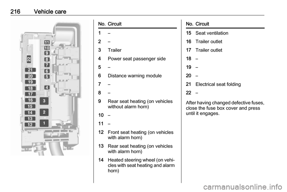
216Vehicle careNo.Circuit1–2–3Trailer4Power seat passenger side5–6Distance warning module7–8–9Rear seat heating (on vehicles
without alarm horn)10–11–12Front seat heating (on vehicles
with alarm horn)13Rear seat heating (on vehicles
with alarm horn)14Heated steering wheel (on vehi‐
cles with seat heating and alarm horn)No.Circuit15Seat ventilation16Trailer outlet17Trailer outlet18–19–20–21Electrical seat folding22–
After having changed defective fuses,
close the fuse box cover and press
until it engages.
Page 224 of 267
222Vehicle carewheel and left side rear wheel. Theturn signal light at the current active
position is illuminated until sensor is
matched.
Consult a workshop for service or purchase a relearn tool. There are
two minutes to match the first wheel
position, and five minutes overall to
match all four wheel positions. If it
takes longer, the matching process
stops and must be restarted.
The tyre pressure sensor matching
process is:
1. Apply the parking brake.
2. Turn the ignition on.
3. On vehicles with automatic transmission: set the selector
lever to P.
On vehicles with manual
transmission: select neutral.
4. Midlevel display: Use MENU on the turn signal
lever to select the Vehicle
Information Menu ? in the
Driver Information Centre.
Uplevel display:Press p on the steering wheel to
open main menu page.
Select the Info page with Q or P.
Confirm with 9.
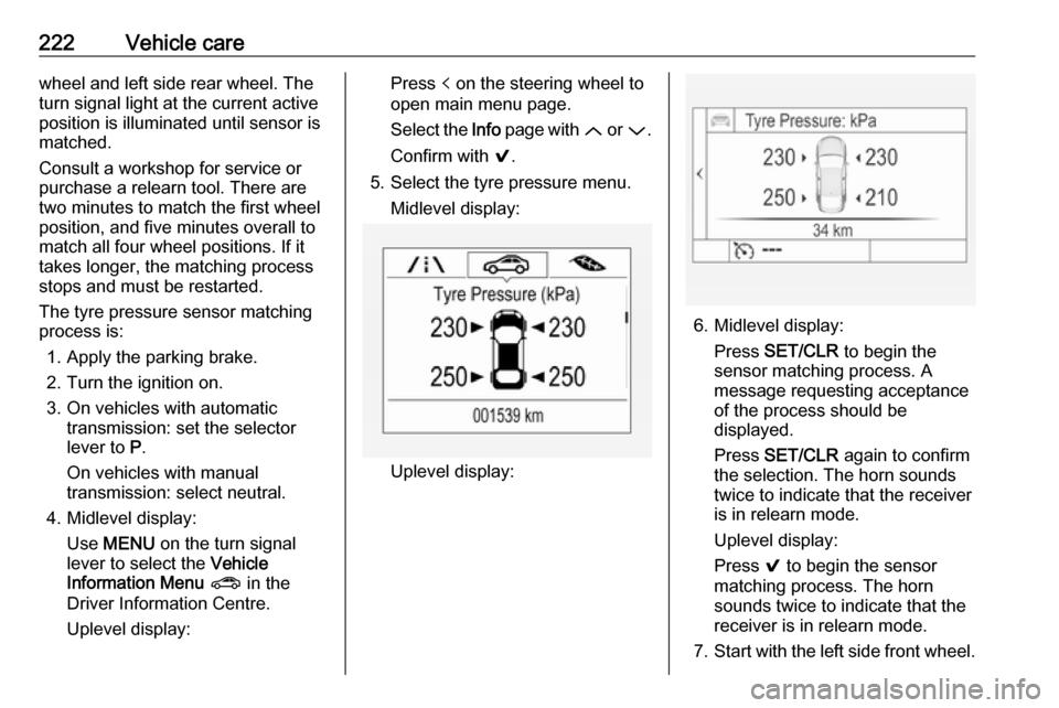
5. Select the tyre pressure menu. Midlevel display:
Uplevel display:
6. Midlevel display: Press SET/CLR to begin the
sensor matching process. A
message requesting acceptance
of the process should be
displayed.
Press SET/CLR again to confirm
the selection. The horn sounds
twice to indicate that the receiver
is in relearn mode.
Uplevel display:
Press 9 to begin the sensor
matching process. The horn
sounds twice to indicate that the receiver is in relearn mode.
7. Start with the left side front wheel.
Page 227 of 267
Vehicle care2259Warning
Do not drive faster than 50 mph.
Do not use for a lengthy period.
Steering and handling may be
affected.
If you have a flat tyre:
Apply the parking brake and engage
first gear, reverse gear or P.
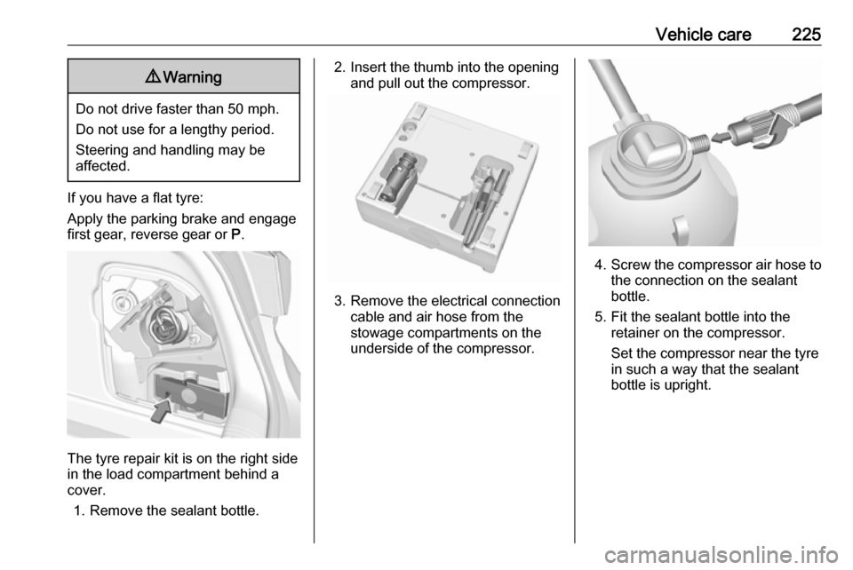
The tyre repair kit is on the right side
in the load compartment behind a
cover.
1. Remove the sealant bottle.
2. Insert the thumb into the opening and pull out the compressor.
3. Remove the electrical connection cable and air hose from the
stowage compartments on the
underside of the compressor.
4. Screw the compressor air hose to
the connection on the sealant
bottle.
5. Fit the sealant bottle into the retainer on the compressor.
Set the compressor near the tyre
in such a way that the sealant
bottle is upright.
Page 236 of 267
234Vehicle careTowingTowing the vehicle
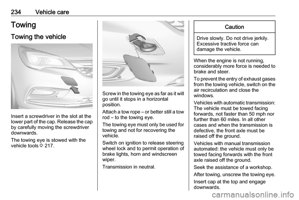
Insert a screwdriver in the slot at the
lower part of the cap. Release the cap
by carefully moving the screwdriver
downwards.
The towing eye is stowed with the
vehicle tools 3 217.
Screw in the towing eye as far as it will
go until it stops in a horizontal
position.
Attach a tow rope – or better still a tow
rod – to the towing eye.
The towing eye must only be used for
towing and not for recovering the
vehicle.
Switch on ignition to release steering wheel lock and to permit operation of
brake lights, horn and windscreen
wiper.
Transmission in neutral.
Caution
Drive slowly. Do not drive jerkily.
Excessive tractive force can
damage the vehicle.
When the engine is not running,
considerably more force is needed to
brake and steer.
To prevent the entry of exhaust gases from the towing vehicle, switch on the
air recirculation and close the
windows.
Vehicles with automatic transmission: The vehicle must be towed facing
forwards, not faster than 50 mph nor further than 60 miles. In all other
cases and when the transmission is
defective, the front axle must be
raised off the ground.
Vehicles with manual transmission
automated: the vehicle must only be
towed facing forwards with the front
axle raised off the ground.
Seek the assistance of a workshop. After towing, unscrew the towing eye.
Insert cap at the top and engage
downwards.
Page 264 of 267

262Head restraints ............................ 40
Heated mirrors ............................. 34
Heated rear window ..................... 38
Heated steering wheel .................76
Heating .................................. 47, 49
Heating and ventilation system . 128
High beam ........................... 96, 118
High beam assist ..........................96
Hill start assist ........................... 159
Horn ....................................... 13, 76
I
Identification plate .....................242
Ignition switch positions .............139
Immobiliser ............................ 33, 96
Indicators ...................................... 87
Info display ................................. 102
Information displays...................... 97
Instrument cluster ........................84
Instrument panel fuse box .........213
Instrument panel illumination .....210
Instrument panel illumination control .................................... 125
Instrument panel overview ........... 10
Interior care ............................... 237
Interior lighting ............................ 125
Interior lights ...................... 125, 210
Interior mirrors .............................. 35
Interruption of power supply ......152
Introduction .................................... 3J
Jump starting ............................. 232
K Key, memorised settings ..............23
Keys ............................................. 19
Keys, locks ................................... 19
L
Lane keep assist ..................94, 185
Lashing eyes ............................... 70
LED headlights .....................96, 119
Lighting features .........................126
Light switch ................................ 117
Load compartment ................29, 67
Load compartment cover .............69
Load compartment fuse box ......215
Loading information .....................72
Low fuel ....................................... 95
M
Malfunction indicator light ............93
Manual anti-dazzle ......................35
Manual mode .....................151, 155
Manual seat adjustment ...............42
Manual transmission .................. 153
Manual transmission automated 154
Manual windows ..........................36
Massage ....................................... 48
Maximum speed ......................... 218
Memorised settings ......................23Mirror adjustment ........................... 9
Misted light covers .....................124
N
New vehicle running-in ..............139
Number plate light .....................209
O Object detection systems ...........170
Odometer ..................................... 88
Oil, engine .......................... 240, 244
OnStar ........................................ 113
Outside temperature ....................79
Overrun cut-off ........................... 144
P Parking ................................ 18, 147
Parking assist ............................ 170
Parking brake ............................ 157
Parking lights ............................. 124
Particulate filter ........................... 148
Performance .............................. 249
Performing work ........................196
Pollen filter ................................. 137
Power button .............................. 140
Power connector........................... 82
Power outlets ............................... 81
Power seat adjustment ................44
Power windows ............................ 36
Preheating ................................... 95
Puncture ..................................... 227
Page 265 of 267

263QQuickheat ................................... 136
R
Radio Frequency Identification (RFID) ..................................... 258
Radio remote control ...................20
Reading lights ............................ 125
Rear floor storage cover ..............70
Rear fog light ....................... 96, 124
Rear seats .................................... 49
Rear view camera ...................... 179
Rear window wiper/washer .......... 78
Recommended fluids and lubricants ........................ 240, 244
Refuelling ................................... 188
Retained power off .....................141
Reversing lights .........................124
Ride control systems ..................159
Roof .............................................. 38
Roof load ...................................... 72
Roof rack ..................................... 72
S Safety belts ................................... 49
Seat adjustment ............................. 7 Seat belt ........................................ 8
Seat belt reminder .......................91
Seat belts ..................................... 49Seat heating Seat heating, front .....................47
Seat heating, rear .....................49
Seat position ................................ 41
Selector lever ..................... 150, 154
Service ............................... 137, 239
Service display ............................ 90
Service information ....................239
Side airbag system ......................55
Side blind spot alert ....................178
Sidelights .................................... 117
Side turn signal lights ................208
Software acknowledgement .......255
Spare wheel ............................... 230
Speed limiter......................... 96, 164
Speedometer ............................... 87
Sport mode ................................ 162
Starting and operating ................139
Starting off ................................... 16
Starting the engine ....................142
Steering ...................................... 139
Steering wheel adjustment ......9, 75
Steering wheel controls ...............75
Stop-start system........................ 144
Storage ......................................... 65
Storage compartments .................65
Sunroof ........................................ 38
Sunvisor lights ........................... 126
Sun visors .................................... 38
Symbols ......................................... 4T
Tachometer ................................. 89
Tail lights ................................... 205
Three-point seat belt .................... 50
Tools .......................................... 217
Tow bar....................................... 190
Towing ................................ 190, 234
Towing another vehicle .............235
Towing equipment .....................191
Towing the vehicle .....................234
Traction Control system ............. 159
Traction Control system off........... 95
Traffic sign assistant .............97, 181
Trailer coupling ........................... 190
Trailer stability assist .................193
Trailer towing ............................. 190
Transmission ............................... 15
Transmission display .........150, 154
Tread depth ............................... 223
Trip odometer .............................. 88
Turn and lane-change signals ...123
Turn signal ................................... 91
Tyre chains ................................ 224
Tyre designations ......................218
Tyre pressure ............................ 218
Tyre pressure monitoring system ............................... 95, 219
Tyre pressures ........................... 253
Tyre repair kit ............................. 224