light VAUXHALL CASCADA 2014 Repair Manual
[x] Cancel search | Manufacturer: VAUXHALL, Model Year: 2014, Model line: CASCADA, Model: VAUXHALL CASCADA 2014Pages: 247, PDF Size: 7.34 MB
Page 194 of 247
192Vehicle care
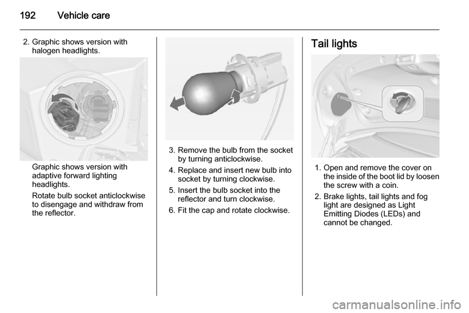
2. Graphic shows version withhalogen headlights.
Graphic shows version with
adaptive forward lighting
headlights.
Rotate bulb socket anticlockwise
to disengage and withdraw from
the reflector.
3. Remove the bulb from the socket by turning anticlockwise.
4. Replace and insert new bulb into socket by turning clockwise.
5. Insert the bulb socket into the reflector and turn clockwise.
6. Fit the cap and rotate clockwise.
Tail lights
1. Open and remove the cover on the inside of the boot lid by loosen
the screw with a coin.
2. Brake lights, tail lights and fog light are designed as Light
Emitting Diodes (LEDs) and
cannot be changed.
Page 195 of 247
Vehicle care193
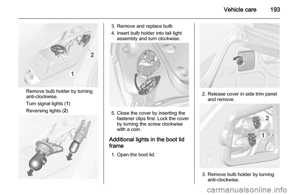
Remove bulb holder by turning
anti-clockwise.
Turn signal lights ( 1)
Reversing lights ( 2)
3. Remove and replace bulb
4. Insert bulb holder into tail light assembly and turn clockwise.
5. Close the cover by inserting thefastener clips first. Lock the cover
by turning the screw clockwise
with a coin.
Additional lights in the boot lid
frame
1. Open the boot lid.
2. Release cover in side trim panel and remove.
3. Remove bulb holder by turninganti-clockwise.
Page 196 of 247
194Vehicle care
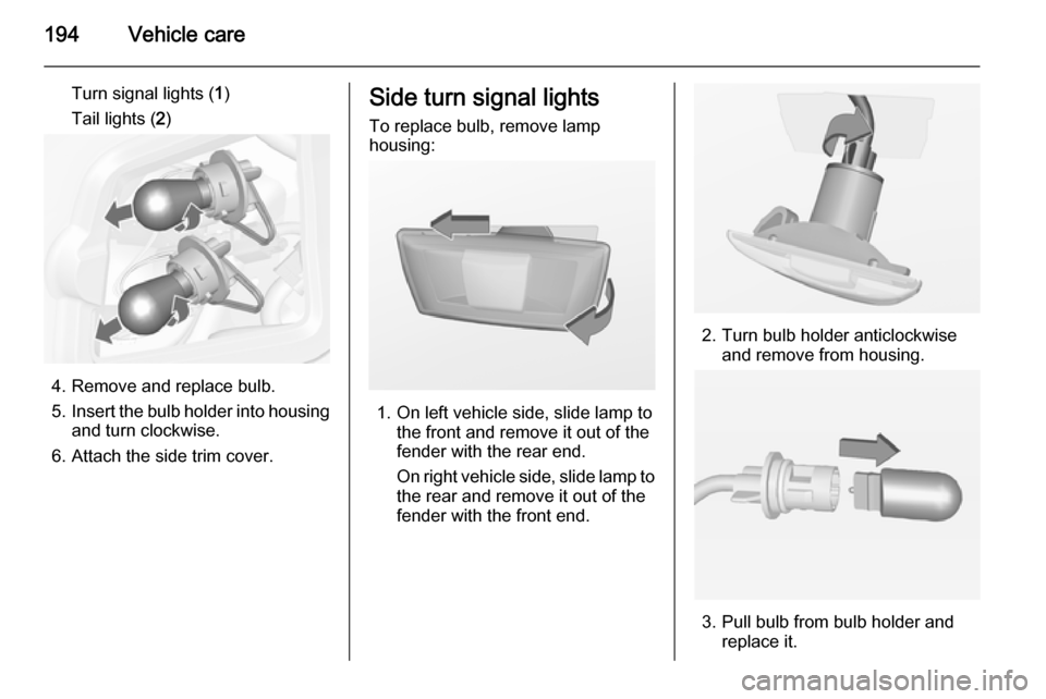
Turn signal lights (1)
Tail lights ( 2)
4. Remove and replace bulb.
5. Insert the bulb holder into housing
and turn clockwise.
6. Attach the side trim cover.
Side turn signal lights
To replace bulb, remove lamp
housing:
1. On left vehicle side, slide lamp to the front and remove it out of the
fender with the rear end.
On right vehicle side, slide lamp to
the rear and remove it out of the fender with the front end.
2. Turn bulb holder anticlockwise and remove from housing.
3. Pull bulb from bulb holder and replace it.
Page 197 of 247
Vehicle care195
4. Insert bulb holder and turnclockwise.
5. On left side: insert front end into fender, slide forward and insert
rear end.
On right side: insert rear end into
fender, slide rearward and insert
front end.
Number plate light
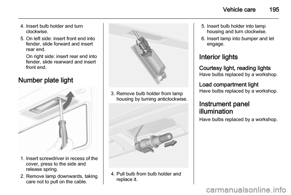
1. Insert screwdriver in recess of the
cover, press to the side and
release spring.
2. Remove lamp downwards, taking care not to pull on the cable.
3. Remove bulb holder from lamphousing by turning anticlockwise.
4. Pull bulb from bulb holder and replace it.
5. Insert bulb holder into lamphousing and turn clockwise.
6. Insert lamp into bumper and let engage.
Interior lights Courtesy light, reading lights
Have bulbs replaced by a workshop.
Load compartment light Have bulbs replaced by a workshop.
Instrument panel
illumination
Have bulbs replaced by a workshop.
Page 199 of 247
Vehicle care197Engine compartment fuse
box
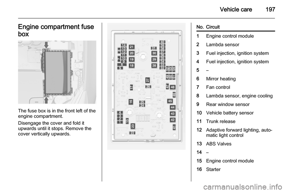
The fuse box is in the front left of the
engine compartment.
Disengage the cover and fold it
upwards until it stops. Remove the
cover vertically upwards.
No.Circuit1Engine control module2Lambda sensor3Fuel injection, ignition system4Fuel injection, ignition system5–6Mirror heating7Fan control8Lambda sensor, engine cooling9Rear window sensor10Vehicle battery sensor11Trunk release12Adaptive forward lighting, auto‐
matic light control13ABS Valves14–15Engine control module16Starter
Page 200 of 247

198Vehicle care
No.Circuit17Transmission control module18Heated rear window19Front power windows20Rear power windows21Rear eletrical centre22Left high beam (Halogen)23Headlamp washer system24Right low beam (Xenon)25Left low beam (Xenon)26Front fog lights27Diesel fuel heating28Start stop system29Electric parking brake30ABS pump31–32AirbagNo.Circuit33Adaptive forward lighting, auto‐
matic light control34Exhaust gas recirculation35Power windows, rain sensor,
exterior mirror36Climate control37–38Vacuum pump39Fuel system control module40Windscreen washer system41Right high beam (Halogen)42Radiator fan43Windscreen wiper44–45Radiator fan46–47HornNo.Circuit48Radiator fan49Fuel pump50Headlamp levelling, adaptive
forward lighting51–52Auxiliary heater, diesel engine53Transmission control module,
Engine control module54Vacuum pump, instrument
panel cluster, heating ventila‐
tion, air conditioning system
After having changed defective fuses,
close the fuse box cover and press
until it engages.
If the fuse box cover is not closed
correctly, malfunctions may occur.
Page 201 of 247
Vehicle care199Instrument panel fuse box
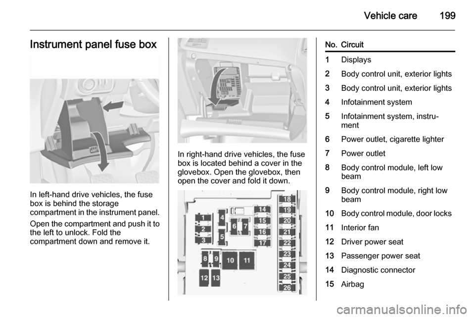
In left-hand drive vehicles, the fuse
box is behind the storage
compartment in the instrument panel.
Open the compartment and push it to the left to unlock. Fold the
compartment down and remove it.
In right-hand drive vehicles, the fuse
box is located behind a cover in the
glovebox. Open the glovebox, then
open the cover and fold it down.
No.Circuit1Displays2Body control unit, exterior lights3Body control unit, exterior lights4Infotainment system5Infotainment system, instru‐
ment6Power outlet, cigarette lighter7Power outlet8Body control module, left low
beam9Body control module, right low
beam10Body control module, door locks11Interior fan12Driver power seat13Passenger power seat14Diagnostic connector15Airbag
Page 202 of 247

200Vehicle care
No.Circuit16Boot lid relay17Air conditioning system18Service diagnose19Body control module, brake
lights, tail lights, interior lights20-21Instrument panel22Ignition system23Body control module24Body control module25–26Trunk power outlet accessory
Load compartment fuse
box
The fuse box is on the left side of the
load compartment behind a cover.
Remove the cover.
Fuse assignments
No.Circuit1Soft top control module, power
rail right2–3Parking assist4–5–6–7Power seat8Soft top control module9–10–11Trailer module, tire pressure
monitor and rear view camera12Soft top control module, tail
lights13–14Rear seat electrical folding15–
Page 208 of 247
206Vehicle care
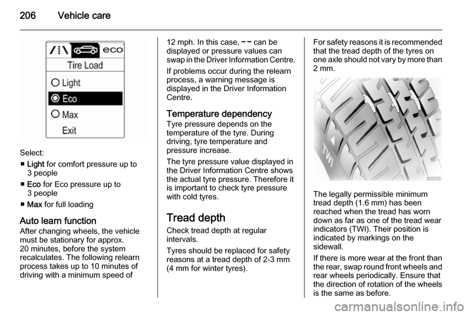
Select:■ Light for comfort pressure up to
3 people
■ Eco for Eco pressure up to
3 people
■ Max for full loading
Auto learn function
After changing wheels, the vehicle
must be stationary for approx.
20 minutes, before the system
recalculates. The following relearn process takes up to 10 minutes of
driving with a minimum speed of
12 mph. In this case, $ can be
displayed or pressure values can
swap in the Driver Information Centre.
If problems occur during the relearn
process, a warning message is
displayed in the Driver Information
Centre.
Temperature dependency Tyre pressure depends on the
temperature of the tyre. During
driving, tyre temperature and
pressure increase.
The tyre pressure value displayed in
the Driver Information Centre shows
the actual tyre pressure. Therefore it
is important to check tyre pressure
with cold tyres.
Tread depth Check tread depth at regular
intervals.
Tyres should be replaced for safety
reasons at a tread depth of 2-3 mm
(4 mm for winter tyres).For safety reasons it is recommended
that the tread depth of the tyres on
one axle should not vary by more than 2 mm.
The legally permissible minimum
tread depth (1.6 mm) has been
reached when the tread has worn
down as far as one of the tread wear
indicators (TWI). Their position is
indicated by markings on the
sidewall.
If there is more wear at the front than
the rear, swap round front wheels and
rear wheels periodically. Ensure that
the direction of rotation of the wheels
is the same as before.
Page 211 of 247
Vehicle care209
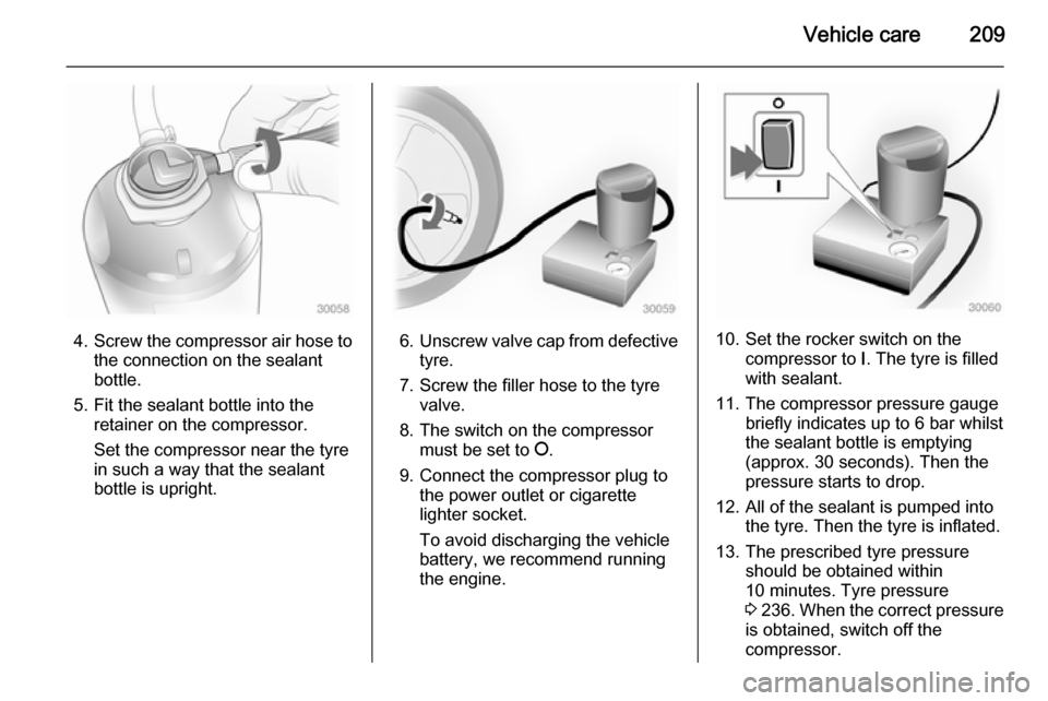
4.Screw the compressor air hose to
the connection on the sealant
bottle.
5. Fit the sealant bottle into the retainer on the compressor.
Set the compressor near the tyre
in such a way that the sealant
bottle is upright.6. Unscrew valve cap from defective
tyre.
7. Screw the filler hose to the tyre valve.
8. The switch on the compressor must be set to J.
9. Connect the compressor plug to the power outlet or cigarette
lighter socket.
To avoid discharging the vehicle
battery, we recommend running
the engine.10. Set the rocker switch on the compressor to I. The tyre is filled
with sealant.
11. The compressor pressure gauge briefly indicates up to 6 bar whilstthe sealant bottle is emptying
(approx. 30 seconds). Then the
pressure starts to drop.
12. All of the sealant is pumped into the tyre. Then the tyre is inflated.
13. The prescribed tyre pressure should be obtained within
10 minutes. Tyre pressure
3 236 . When the correct pressure
is obtained, switch off the
compressor.