display VAUXHALL COMBO 2014 Owner's Manual
[x] Cancel search | Manufacturer: VAUXHALL, Model Year: 2014, Model line: COMBO, Model: VAUXHALL COMBO 2014Pages: 187, PDF Size: 4.15 MB
Page 5 of 187

Introduction3Vehicle specific data
Please enter your vehicle's data on
the previous page to keep it easily
accessible. This information is
available in the sections "Service and maintenance" and "Technical data"
as well as on the identification plate.
Introduction
Your vehicle is a designed
combination of advanced technology, safety, environmental friendliness
and economy.
This Owner's Manual provides you
with all the necessary information to
enable you to drive your vehicle
safely and efficiently.
Make sure your passengers are
aware of the possible risk of accident
and injury which may result from
improper use of the vehicle.
You must always comply with the
specific laws and regulations of the
country that you are in. These laws
may differ from the information in this Owner's Manual.When this Owner's Manual refers to aworkshop visit, we recommend your
Vauxhall Authorised Repairer.
All Vauxhall Authorised Repairers
provide first-class service at
reasonable prices. Experienced
mechanics trained by Vauxhall work
according to specific Vauxhall
instructions.
The customer literature pack should
always be kept ready to hand in the
vehicle.
Using this manual ■ This manual describes all options and features available for this
model. Certain descriptions,
including those for display and
menu functions, may not apply to
your vehicle due to model variant,
country specifications, special
equipment or accessories.
■ The "In brief" section will give you an initial overview.
■ The table of contents at the beginning of this manual and withineach section shows where the
information is located.■ The index will enable you to search
for specific information.
■ This Owner's Manual depicts left- hand drive vehicles. Operation is
similar for right-hand drive vehicles.
■ The Owner's Manual uses the factory engine designations. The
corresponding sales designations
can be found in the section
"Technical data".
■ Directional data, e.g. left or right, or
front or back, always relate to the
direction of travel.
■ The vehicle display screens may not support your specific language.
■ Display messages and interior labelling are written in bold letters.
Danger, Warnings and
Cautions9 Danger
Text marked 9 Danger provides
information on risk of fatal injury.
Disregarding this information may
endanger life.
Page 19 of 187
In brief17
■ diesel engines: turn the key toposition MAR for preheating and
wait until control indicator ! goes
out
■ turn key to position AVV and
release
Starting the engine 3 102.Stop-start system
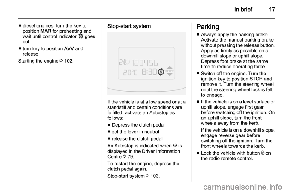
If the vehicle is at a low speed or at a
standstill and certain conditions are
fulfilled, activate an Autostop as
follows:
■ Depress the clutch pedal
■ set the lever in neutral
■ release the clutch pedal
An Autostop is indicated when ^ is
displayed in the Driver Information
Centre 3 79.
To restart the engine, depress the
clutch pedal again.
Stop-start system 3 103.
Parking
■ Always apply the parking brake. Activate the manual parking brake
without pressing the release button.
Apply as firmly as possible on a
downhill slope or uphill slope.
Depress foot brake at the same
time to reduce operating force.
■ Switch off the engine. Turn the ignition key to position STOP and
remove it. Turn the steering wheel
until the steering wheel lock is felt
to engage.
■ If the vehicle is on a level surface or
uphill slope, engage first gear
before switching off the ignition. On
an uphill slope, turn the front
wheels away from the kerb.
If the vehicle is on a downhill slope, engage reverse gear before
switching off the ignition. Turn the
front wheels towards the kerb.
■ Lock the vehicle with button e on
the radio remote control.
Page 35 of 187
Seats, restraints33
Rear head restraints, heightadjustment
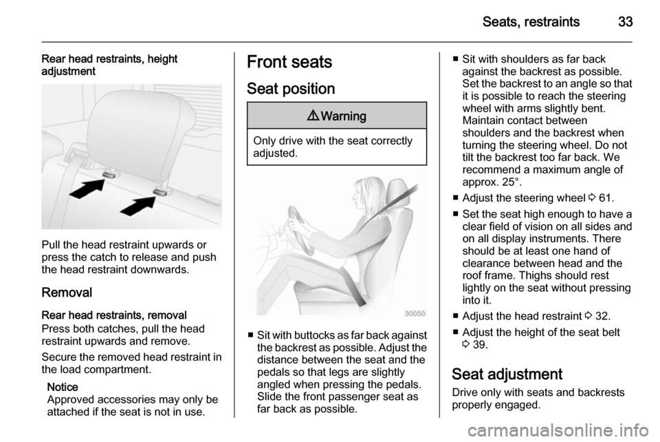
Pull the head restraint upwards or
press the catch to release and push the head restraint downwards.
Removal
Rear head restraints, removal
Press both catches, pull the head restraint upwards and remove.
Secure the removed head restraint in the load compartment.
Notice
Approved accessories may only be
attached if the seat is not in use.
Front seats
Seat position9 Warning
Only drive with the seat correctly
adjusted.
■ Sit with buttocks as far back against
the backrest as possible. Adjust the distance between the seat and the
pedals so that legs are slightly
angled when pressing the pedals.
Slide the front passenger seat as
far back as possible.
■ Sit with shoulders as far back against the backrest as possible.
Set the backrest to an angle so that it is possible to reach the steering
wheel with arms slightly bent.
Maintain contact between
shoulders and the backrest when
turning the steering wheel. Do not
tilt the backrest too far back. We
recommend a maximum angle of
approx. 25°.
■ Adjust the steering wheel 3 61.
■ Set the seat high enough to have a
clear field of vision on all sides and
on all display instruments. There
should be at least one hand of
clearance between head and the
roof frame. Thighs should rest
lightly on the seat without pressing
into it.
■ Adjust the head restraint 3 32.
■ Adjust the height of the seat belt 3 39.
Seat adjustment Drive only with seats and backrests
properly engaged.
Page 48 of 187
46Seats, restraints
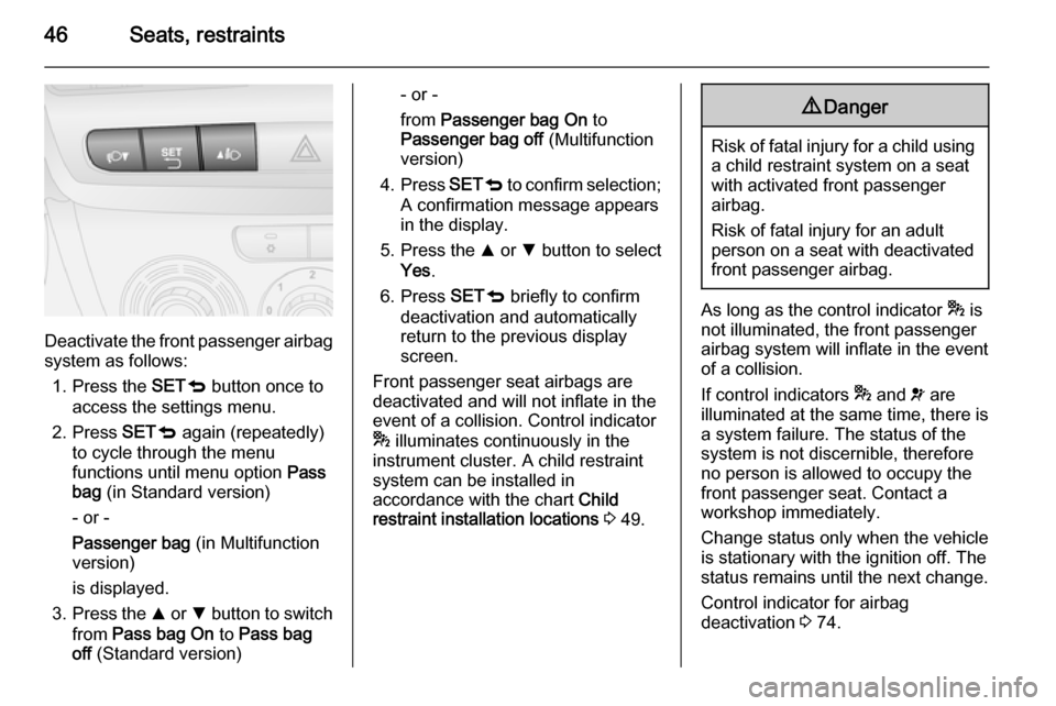
Deactivate the front passenger airbagsystem as follows:
1. Press the SETq button once to
access the settings menu.
2. Press SETq again (repeatedly)
to cycle through the menu
functions until menu option Pass
bag (in Standard version)
- or -
Passenger bag (in Multifunction
version)
is displayed.
3. Press the R or S button to switch
from Pass bag On to Pass bag
off (Standard version)
- or -
from Passenger bag On to
Passenger bag off (Multifunction
version)
4. Press SETq to confirm selection;
A confirmation message appears
in the display.
5. Press the R or S button to select
Yes .
6. Press SETq briefly to confirm
deactivation and automatically
return to the previous display
screen.
Front passenger seat airbags are deactivated and will not inflate in the
event of a collision. Control indicator
* illuminates continuously in the
instrument cluster. A child restraint
system can be installed in
accordance with the chart Child
restraint installation locations 3 49.9 Danger
Risk of fatal injury for a child using
a child restraint system on a seat
with activated front passenger
airbag.
Risk of fatal injury for an adult
person on a seat with deactivated
front passenger airbag.
As long as the control indicator * is
not illuminated, the front passenger
airbag system will inflate in the event
of a collision.
If control indicators * and v are
illuminated at the same time, there is
a system failure. The status of the system is not discernible, therefore
no person is allowed to occupy the
front passenger seat. Contact a
workshop immediately.
Change status only when the vehicle
is stationary with the ignition off. The
status remains until the next change.
Control indicator for airbag
deactivation 3 74.
Page 63 of 187
Instruments and controls61Instruments and
controlsControls ....................................... 61
Warning lights, gauges and indi‐ cators ........................................... 67
Information displays .....................79
Vehicle messages ........................ 85
Trip computer ............................... 86Controls
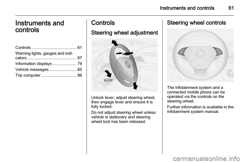
Steering wheel adjustment
Unlock lever, adjust steering wheel,
then engage lever and ensure it is fully locked.
Do not adjust steering wheel unless
vehicle is stationary and steering
wheel lock has been released.
Steering wheel controls
The Infotainment system and a
connected mobile phone can be
operated via the controls on the
steering wheel.
Further information is available in the
Infotainment system manual.
Page 65 of 187
Instruments and controls63Rear window wiper/washer
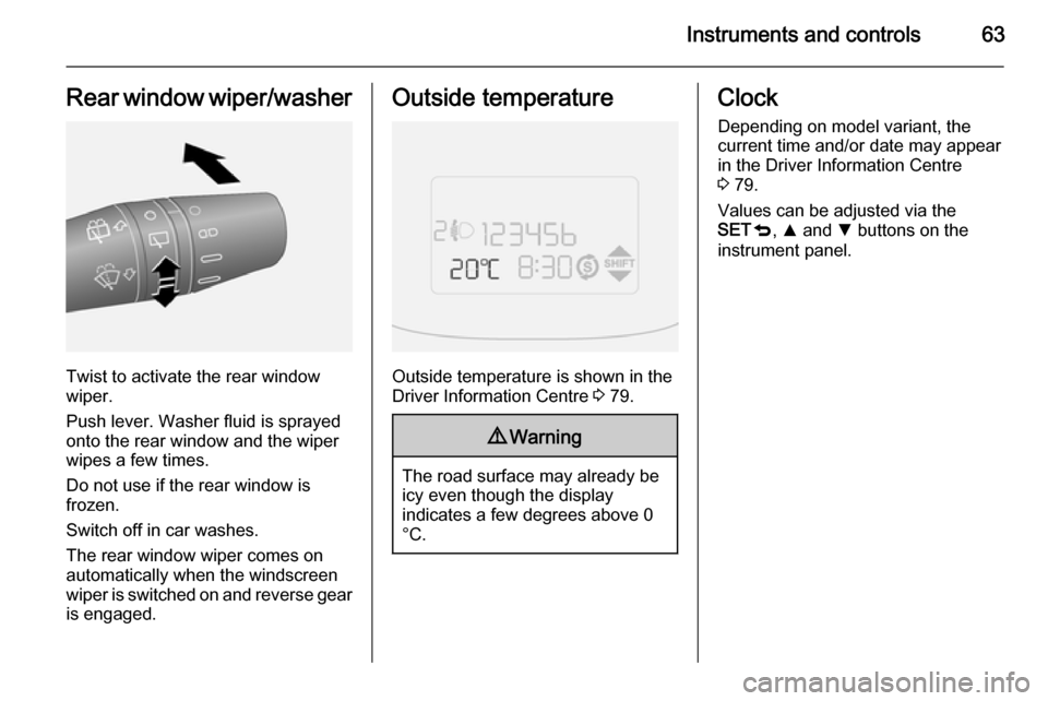
Twist to activate the rear window
wiper.
Push lever. Washer fluid is sprayed
onto the rear window and the wiper
wipes a few times.
Do not use if the rear window is
frozen.
Switch off in car washes.
The rear window wiper comes on
automatically when the windscreen
wiper is switched on and reverse gear
is engaged.
Outside temperature
Outside temperature is shown in the
Driver Information Centre 3 79.
9 Warning
The road surface may already be
icy even though the display
indicates a few degrees above 0
°C.
Clock
Depending on model variant, the
current time and/or date may appear
in the Driver Information Centre
3 79.
Values can be adjusted via the
SET q, R and S buttons on the
instrument panel.
Page 66 of 187
64Instruments and controls
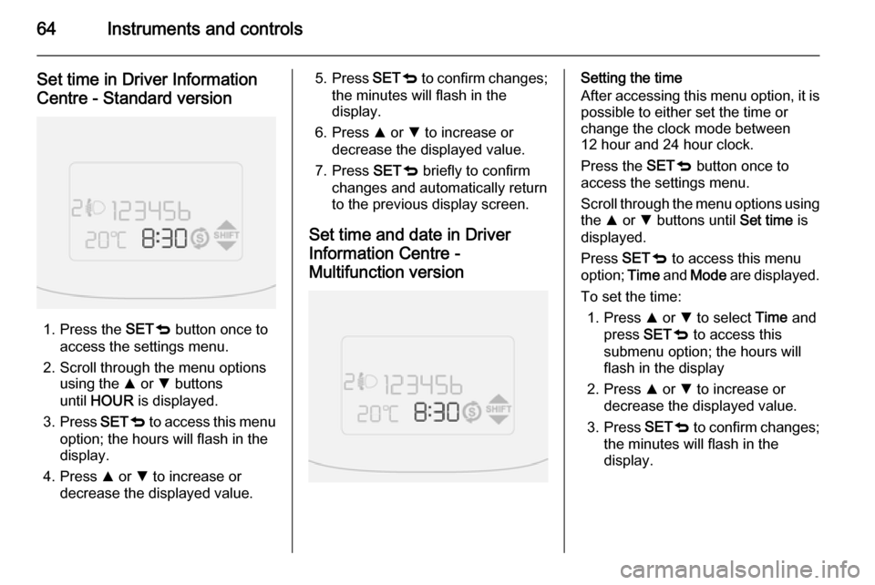
Set time in Driver Information
Centre - Standard version
1. Press the SETq button once to
access the settings menu.
2. Scroll through the menu options using the R or S buttons
until HOUR is displayed.
3. Press SETq to access this menu
option; the hours will flash in the display.
4. Press R or S to increase or
decrease the displayed value.
5. Press SETq to confirm changes;
the minutes will flash in the
display.
6. Press R or S to increase or
decrease the displayed value.
7. Press SETq briefly to confirm
changes and automatically return
to the previous display screen.
Set time and date in Driver
Information Centre -
Multifunction versionSetting the time
After accessing this menu option, it is possible to either set the time or
change the clock mode between
12 hour and 24 hour clock.
Press the SETq button once to
access the settings menu.
Scroll through the menu options using
the R or S buttons until Set time is
displayed.
Press SETq to access this menu
option; Time and Mode are displayed.
To set the time: 1. Press R or S to select Time and
press SETq to access this
submenu option; the hours will
flash in the display
2. Press R or S to increase or
decrease the displayed value.
3. Press SETq to confirm changes;
the minutes will flash in the display.
Page 67 of 187

Instruments and controls65
4. Press R or S to increase or
decrease the displayed value.
5. Press SETq briefly to confirm
changes and automatically return
to the previous display screen.
To change the clock mode between 12 hour and 24 hour clock:
1. Press R or S to select Mode and
press SETq to access this
submenu option; the display will
flash.
2. Press R or S to change clock
mode between 12h and 24h.
3. Press SETq briefly to confirm
changes and automatically return to the previous display screen.
Setting the date 1. Press the SETq button once to
access the settings menu.
2. Scroll through the menu options using the R or S buttons until Set
date is displayed.
3. Press SETq to access this menu
option; the year will flash in the
display.4. Press R or S to increase or
decrease the displayed value.
5. Press SETq to confirm changes;
the month will flash in the display.
6. Press R or S to increase or
decrease the displayed value.
7. Press SETq to confirm changes;
the day will flash in the display.
8. Press R or S to increase or
decrease the displayed value.
9. Press SETq briefly to confirm
changes and automatically return to the previous display screen.Power outlets
A 12 Volt power outlet is located in the
centre console.
Rear power outlets
Depending on model variant,12 Volt
power outlets are located at the
sidewall in the load compartment.
Page 69 of 187
Instruments and controls67AshtraysCaution
To be used only for ash and not forcombustible rubbish.
The portable ashtray should be
placed in the cupholders in the centre
console.
Warning lights, gauges
and indicators
Instrument cluster
The needles of the instruments briefly rotate to the end position when the
ignition is switched on.
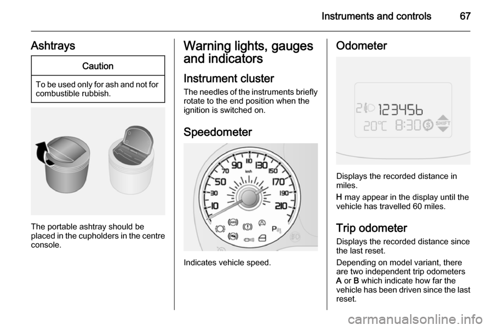
Speedometer
Indicates vehicle speed.
Odometer
Displays the recorded distance in
miles.
H may appear in the display until the
vehicle has travelled 60 miles.
Trip odometer Displays the recorded distance since
the last reset.
Depending on model variant, there are two independent trip odometers
A or B which indicate how far the
vehicle has been driven since the last
reset.
Page 70 of 187
68Instruments and controls
To reset the trip odometer, press andhold the TRIP button for a few
seconds while the relevant trip
odometer is displayed.
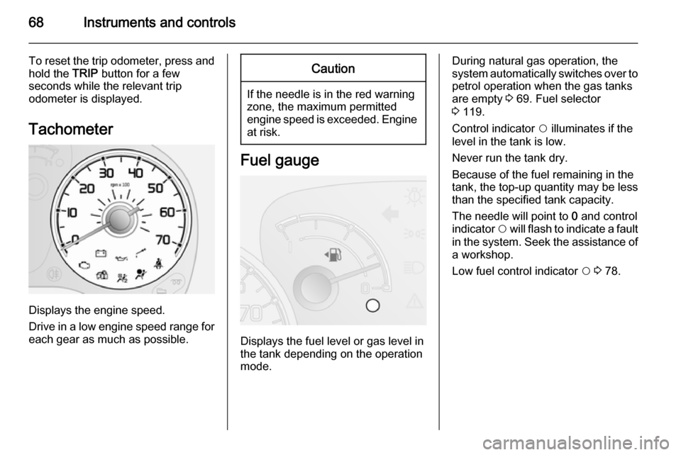
Tachometer
Displays the engine speed.
Drive in a low engine speed range for each gear as much as possible.
Caution
If the needle is in the red warning
zone, the maximum permitted
engine speed is exceeded. Engine at risk.
Fuel gauge
Displays the fuel level or gas level in
the tank depending on the operation
mode.
During natural gas operation, the
system automatically switches over to
petrol operation when the gas tanks
are empty 3 69. Fuel selector
3 119.
Control indicator $ illuminates if the
level in the tank is low.
Never run the tank dry.
Because of the fuel remaining in the
tank, the top-up quantity may be less
than the specified tank capacity.
The needle will point to 0 and control
indicator $ will flash to indicate a fault
in the system. Seek the assistance of a workshop.
Low fuel control indicator $ 3 78.