ESP VAUXHALL COMBO E 2020 Service Manual
[x] Cancel search | Manufacturer: VAUXHALL, Model Year: 2020, Model line: COMBO E, Model: VAUXHALL COMBO E 2020Pages: 279, PDF Size: 28.6 MB
Page 190 of 279
188Driving and operating
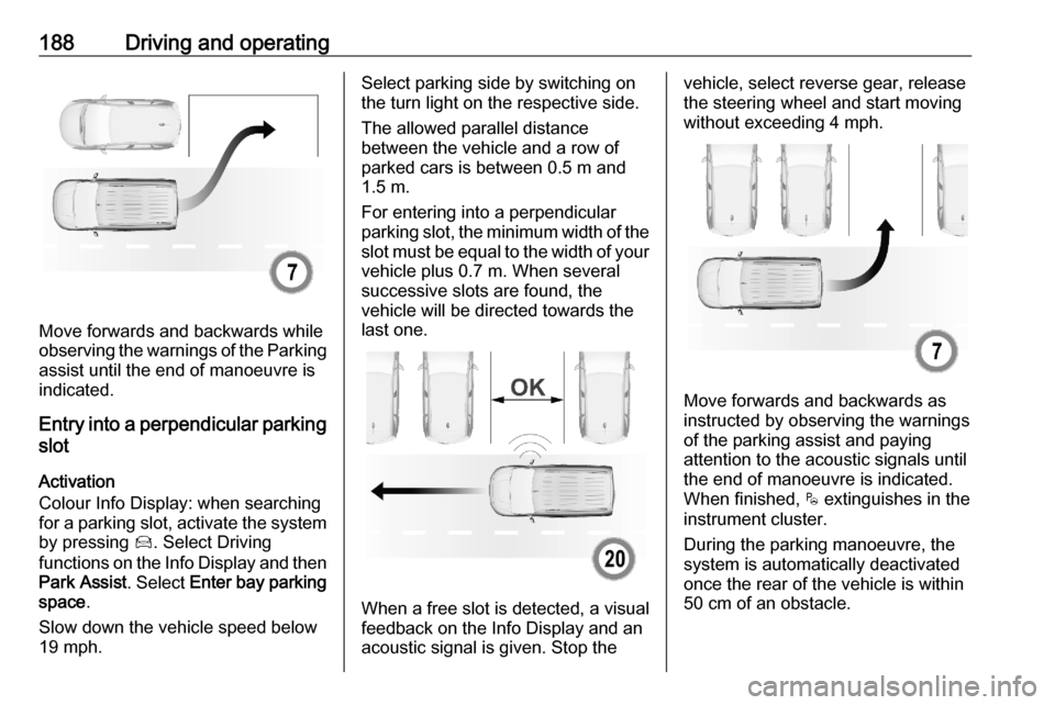
Move forwards and backwards while
observing the warnings of the Parking
assist until the end of manoeuvre is
indicated.
Entry into a perpendicular parking
slot
Activation
Colour Info Display: when searching
for a parking slot, activate the system by pressing Í. Select Driving
functions on the Info Display and then
Park Assist . Select Enter bay parking
space .
Slow down the vehicle speed below
19 mph.
Select parking side by switching on
the turn light on the respective side.
The allowed parallel distance
between the vehicle and a row of
parked cars is between 0.5 m and
1.5 m.
For entering into a perpendicular parking slot, the minimum width of the
slot must be equal to the width of your vehicle plus 0.7 m. When several
successive slots are found, the
vehicle will be directed towards the
last one.
When a free slot is detected, a visual
feedback on the Info Display and an
acoustic signal is given. Stop the
vehicle, select reverse gear, release
the steering wheel and start moving
without exceeding 4 mph.
Move forwards and backwards as
instructed by observing the warnings of the parking assist and paying
attention to the acoustic signals until
the end of manoeuvre is indicated.
When finished, $ extinguishes in the
instrument cluster.
During the parking manoeuvre, the
system is automatically deactivated
once the rear of the vehicle is within
50 cm of an obstacle.
Page 191 of 279
Driving and operating189Exiting a parallel parking slotActivation
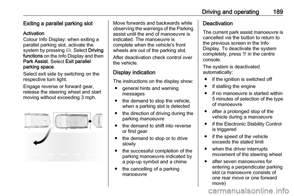
Colour Info Display: when exiting a
parallel parking slot, activate the
system by pressing Í. Select Driving
functions on the Info Display and then
Park Assist . Select Exit parallel
parking space .
Select exit side by switching on the
respective turn light.
Engage reverse or forward gear,
release the steering wheel and start
moving without exceeding 3 mph.Move forwards and backwards while
observing the warnings of the Parking
assist until the end of manoeuvre is
indicated. The manoeuvre is
complete when the vehicle's front
wheels are out of the parking slot.
After deactivation check control over
the vehicle.
Display indication
The instructions on the display show: ● general hints and warning messages
● the demand to stop the vehicle, when a parking slot is detected
● the direction of driving during the
parking manoeuvre
● the demand to shift into reverse or first gear
● the demand to stop or to drive slowly
● the successful completion of the parking manoeuvre indicated bya pop-up symbol and a chime
● the cancelling of a parking manoeuvreDeactivation
The current park assist manoeuvre is cancelled via the button to return to
the previous screen in the Info
Display. To deactivate the system
completely, press ¼ in the centre
console.
The system is deactivated
automatically:
● if the ignition is switched off
● if stalling the engine
● if no manoeuvre is started within 5 minutes of selection of the typeof manoeuvre
● after a prolonged stop of the vehicle during a manoeuvre
● if the Electronic Stability Control is triggered
● if the speed of the vehicle exceeds the stated limit
● when the driver interrupts movement of the steering wheel
● after seven manoeuvres for entering a perpendicular parking
slot (a manoeuvre consists of
one rear move or one forward
move)
Page 192 of 279
190Driving and operating●after ten manoeuvres for entering
or exiting a parallel parking slot
● on opening a door or the load compartment
● if one of the front wheels encounters an obstacle
● parking manoeuvre successfully ended
Deactivation by the driver or by the
system during manoeuvring will be
indicated on the display. Additionally,
an acoustic signal sounds.
The system is switched off
automatically when towing an
electrically connected trailer, bicycle
carrier, etc.
Contact your dealer to switch off the
system for a prolonged period.
Fault
In the event of a fault, a message is
displayed in the Colour Info Display, accompanied by an acoustic signal.
In the event of a fault in the power
steering, C illuminates and a
message is displayed in the Driver
Information Centre.9 Warning
Under certain circumstances,
various reflective surfaces on
objects or clothing as well as
external noise sources may cause the system to fail to detect
obstacles.
Special attention must be paid to
low obstacles which can damage
the lower part of the bumper.
Caution
Performance of the system can be reduced when sensors are
covered, e.g. by ice or snow.
Performance of the parking assist
system can be reduced due to
heavy loading.
Special conditions apply if there
are taller vehicles in the vicinity
(e.g. off-road vehicles, mini vans,
vans). Object identification and correct distance indication in the
upper part of these vehicles
cannot be guaranteed.
Objects with a very small reflection
cross-section, e.g. objects of
narrow size or soft materials, may
not be detected by the system.
Parking assist systems do not
detect objects outside the
detection range.
Notice
It is possible that the sensor detects a non-existing object caused by
echo disturbance from external
acoustic noise or mechanical
misalignments (sporadic false
warnings may occur).
Make sure that the front number
plate is properly mounted (not bent
and no gaps to the bumper on the left
or right side) and the sensors are
firmly in place.
Advanced parking assist system
may not respond to changes in the
available parking space after
initiating a parking manoeuvre. The
system may recognize an entry, a
gateway, a courtyard or even a crossing as a parking slot. After
selecting reverse gear the system
Page 193 of 279
Driving and operating191will start a parking manoeuvre. Take
care regarding the availability of the
suggested parking slot.
Surface irregularities, e.g. on
construction zones, are not detected
by the system. The driver accepts
responsibility.
Side blind spot alert The side blind spot alert system
detects and reports objects on either
side of the vehicle, within a specified
blind spot zone. The system displays
a visual alert in each exterior mirror,
when detecting objects that may not
be visible in the interior and exterior
mirrors.
Side blind spot alert uses some of the advanced parking assist sensors
which are located in the front and rear
bumper on both sides of the vehicle.9 Warning
Side blind spot alert does not
replace driver vision.
The system does not detect:
● vehicles outside the side blind zones which may be rapidly
approaching
● pedestrians, cyclists or animals
Before changing a lane, always
check all mirrors, look over the
shoulder and use the turn signal.
Activation
Colour Info Display: press Í. Select
Driving functions on the Info Display
and then Blind spot sensors . Activate
the function.
B illuminates continously green in the
instrument cluster to confirm the
function.
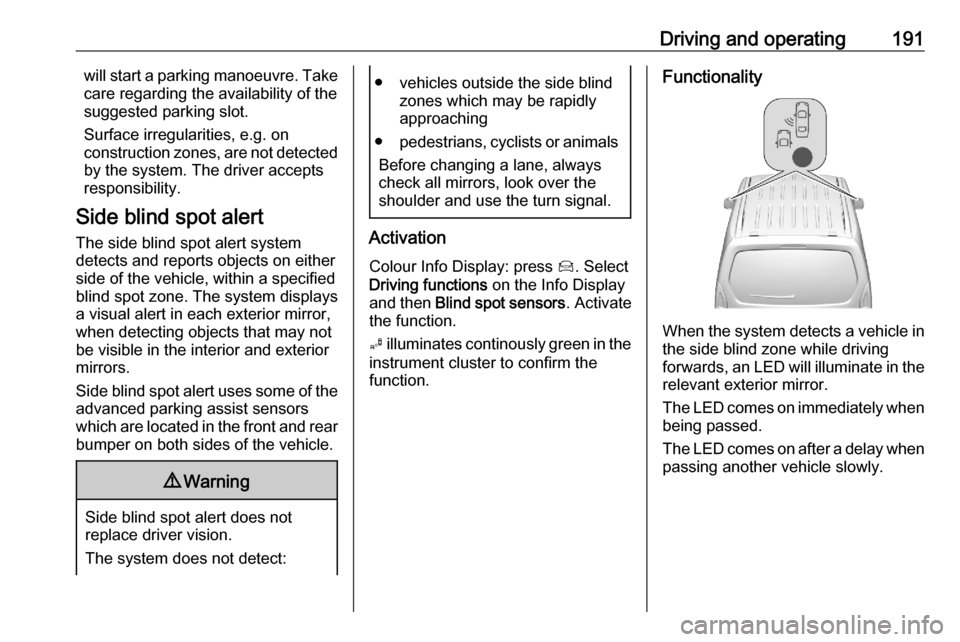
Functionality
When the system detects a vehicle in the side blind zone while driving
forwards, an LED will illuminate in the
relevant exterior mirror.
The LED comes on immediately when being passed.
The LED comes on after a delay when
passing another vehicle slowly.
Page 201 of 279
Driving and operating199● the change of trajectory is notaccompanied by operation of theturn signals
● the Electronic Stability Control is activated and not in operation
● the vehicle is not connected to a trailer or an electric bicycle carrier
● normal driving behaviour (system
detects dynamic driving style, i.e. pressure on the brake or
accelerator pedal)
● roads with poor lane markings
● no spare wheel is used
● the driver needs to be active during the correction
● the vehicle is not driven in a tight
cornerActivation
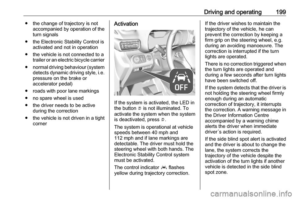
If the system is activated, the LED in
the button Ó is not illuminated. To
activate the system when the system
is deactivated, press Ó.
The system is operational at vehicle
speeds between 40 mph and
112 mph and if lane markings are
detectable. The driver must hold the
steering wheel with both hands. The Electronic Stability Control system
must be activated.
The control indicator a flashes
yellow during trajectory correction.
If the driver wishes to maintain the
trajectory of the vehicle, he can
prevent the correction by keeping a
firm grip on the steering wheel, e.g.
during an avoiding manoeuvre. The correction is interrupted if the turn
lights are operated.
There is no correction triggered when
the turn lights are operated and
during a few seconds after turn lights
have been switched off.
If the system detects that the driver is not holding the steering wheel firmly
enough during an automatic
correction of trajectory, it interrupts
the correction. A warning message in
the Driver Information Centre
accompanied by a warning chime
alerts the driver when immediate
driver´s action is required.
If the side blind spot alert is activated
and the driver is about to change the
lane, the system corrects the
trajectory of the vehicle despite the
activation of the turn lights if another
vehicle is detected in the side blind
spot zone.
Page 202 of 279

200Driving and operatingDeactivation
To deactivate the system, press and
hold Ó. Deactivation of the system is
confirmed by the illuminated LED in
the button. In the Driver Information
Centre solid grey lines are displayed.
Recommended deactivation
It is recommended to deactivate the
system in the following situations:
● Road surface in poor condition
● Unfavourable climatic conditions
● Slippery surfaces, e.g., ice
The system is not designed for driving in the following situations:
● Driving on a speed circuit
● Driving with a trailer
● Driving on a rolling stand
● Driving on unstable surfacesFault
In the event of a fault, a and C
appear in the instrument panel,
accompanied by a display message
and a warning chime. Contact a
dealer or a qualified workshop to have the system checked.
System limitations The system performance may be
affected by:
● windscreen not clean or affected by foreign objects, e.g. stickers
● close vehicles ahead
● banked roads
● narrow, winding or hilly roads
● road edges
● sudden lighting changes
● adverse environmental conditions, e.g. heavy rain or
snow
● vehicle modifications, e.g. tyresSwitch off the system if the system is
disturbed by tar marks, shadows,
road cracks, temporary or
construction lane markings, or other
road imperfections.9 Warning
Always keep your attention on the
road and maintain proper vehicle
position within the lane, otherwise
vehicle damage, injury or death
could occur.
Lane keep assist does not
continuously steer the vehicle.
The system may not keep the
vehicle in the lane or give an alert,
even if a lane marking is detected.
The steering of the lane keep
assist may not be sufficient to
avoid a lane departure.
The system may not detect hands-
off driving due to external
influences like road condition and
surface and weather. The driver has full responsibility to control the
Page 209 of 279

Driving and operating207The permissible gross train weight
must not be exceeded. This weight is
specified on the identification plate
3 256.
Vertical coupling load
The vertical coupling load is the load
exerted by the trailer on the coupling
ball. It can be varied by changing the
weight distribution when loading the
trailer.
The maximum permissible vertical
coupling load is specified on the
towing equipment identification plate
and in the vehicle documents.
Always aim for the maximum vertical
coupling load, especially in the case
of heavy trailers. The vertical coupling load should never fall below 25 kg.
Rear axle load When the trailer is coupled and the
towing vehicle fully loaded, the
permissible rear axle load (see
identification plate or vehicle
documents) may be exceeded by
60 kg , the gross vehicle weight rating
must not be exceeded. If thepermissible rear axle load is
exceeded, a maximum speed of
60 mph applies.
Towing equipment
Depending on version the vehicle can be fitted with a detachable or a fixed
coupling ball bar.
Type ACaution
When operating without a trailer,
remove the coupling ball bar.
Fitting the coupling ball bar
1. Place the key in the lock and
unlock the coupling ball bar. Move
the lever to the rear position.
2. Clean the contact points with a soft clean cloth.
Page 216 of 279
214Vehicle care
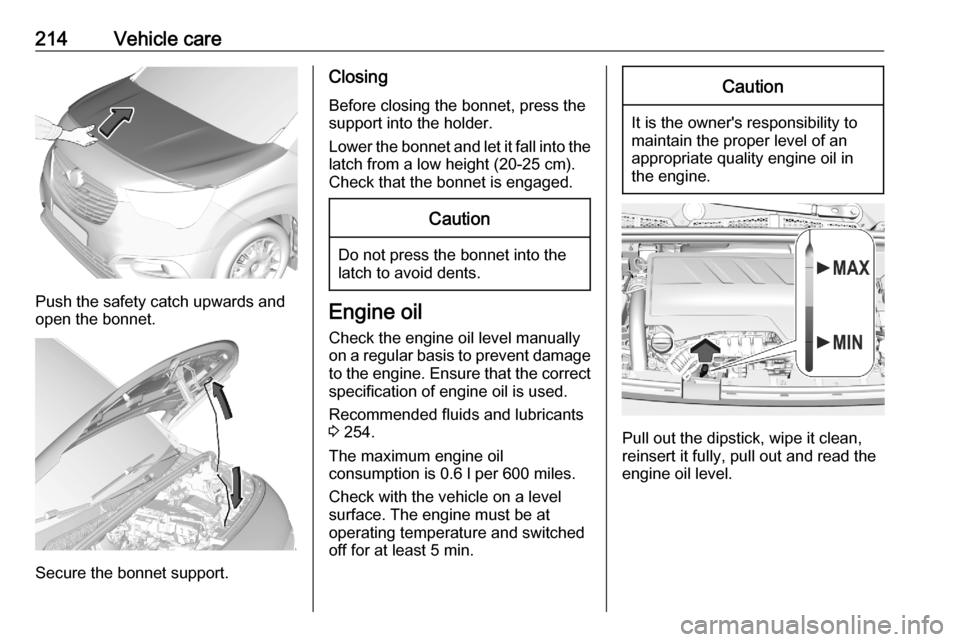
Push the safety catch upwards and
open the bonnet.
Secure the bonnet support.
Closing
Before closing the bonnet, press the
support into the holder.
Lower the bonnet and let it fall into the
latch from a low height (20-25 cm).
Check that the bonnet is engaged.Caution
Do not press the bonnet into the
latch to avoid dents.
Engine oil
Check the engine oil level manually
on a regular basis to prevent damage
to the engine. Ensure that the correct
specification of engine oil is used.
Recommended fluids and lubricants
3 254.
The maximum engine oil
consumption is 0.6 l per 600 miles.
Check with the vehicle on a level
surface. The engine must be at
operating temperature and switched
off for at least 5 min.
Caution
It is the owner's responsibility to
maintain the proper level of an
appropriate quality engine oil in
the engine.
Pull out the dipstick, wipe it clean, reinsert it fully, pull out and read the
engine oil level.
Page 229 of 279
Vehicle care227Number plate light
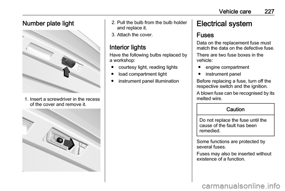
1. Insert a screwdriver in the recessof the cover and remove it.
2. Pull the bulb from the bulb holderand replace it.
3. Attach the cover.
Interior lights
Have the following bulbs replaced by
a workshop:
● courtesy light, reading lights
● load compartment light
● instrument panel illuminationElectrical system
Fuses
Data on the replacement fuse must
match the data on the defective fuse.
There are two fuse boxes in the
vehicle:
● engine compartment
● instrument panel
Before replacing a fuse, turn off the
respective switch and the ignition.
A blown fuse can be recognised by its melted wire.Caution
Do not replace the fuse until the
cause of the fault has been
remedied.
Some functions are protected by
several fuses.
Fuses may also be inserted without
existence of a function.
Page 234 of 279
232Vehicle careDirectional tyres
Directional tyres should be mounted so that they rotate in the correct
direction. The proper rotation
direction is indicated by a symbol
(e.g. an arrow) on the sidewall.
Tyre pressure
Check the pressure of cold tyres at
least every 14 days and before any
long journey. Do not forget the spare
wheel. This also applies to vehicles
with tyre pressure monitoring system.
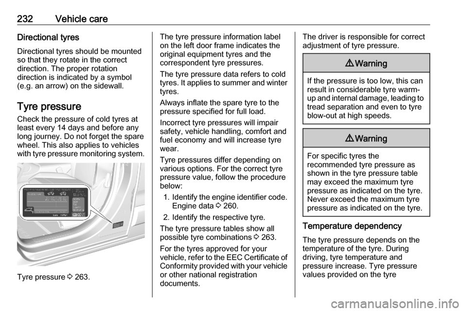
Tyre pressure 3 263.
The tyre pressure information label
on the left door frame indicates the
original equipment tyres and the
correspondent tyre pressures.
The tyre pressure data refers to cold
tyres. It applies to summer and winter tyres.
Always inflate the spare tyre to the
pressure specified for full load.
Incorrect tyre pressures will impair
safety, vehicle handling, comfort and
fuel economy and will increase tyre
wear.
Tyre pressures differ depending on
various options. For the correct tyre
pressure value, follow the procedure
below:
1. Identify the engine identifier code.
Engine data 3 260.
2. Identify the respective tyre.
The tyre pressure tables show all
possible tyre combinations 3 263.
For the tyres approved for your
vehicle, refer to the EEC Certificate of Conformity provided with your vehicle
or other national registration
documents.The driver is responsible for correct adjustment of tyre pressure.9 Warning
If the pressure is too low, this can
result in considerable tyre warm-
up and internal damage, leading to tread separation and even to tyre
blow-out at high speeds.
9 Warning
For specific tyres the
recommended tyre pressure as
shown in the tyre pressure table may exceed the maximum tyre
pressure as indicated on the tyre.
Never exceed the maximum tyre
pressure as indicated on the tyre.
Temperature dependency
The tyre pressure depends on the
temperature of the tyre. During
driving, tyre temperature and
pressure increase. Tyre pressure
values provided on the tyre