warning VAUXHALL CORSA 2014.5 Owner's Guide
[x] Cancel search | Manufacturer: VAUXHALL, Model Year: 2014.5, Model line: CORSA, Model: VAUXHALL CORSA 2014.5Pages: 231, PDF Size: 6.8 MB
Page 55 of 231

Storage53StorageStorage compartments................53
Load compartment .......................63
Roof rack system .........................67
Loading information .....................68Storage compartments9Warning
Do not store heavy or sharp
objects in the storage
compartments. Otherwise, the
storage compartment lid could
open and vehicle occupants could be injured by objects being thrown
around in the event of hard
braking, a sudden change in
direction or an accident.
Glovebox
The glovebox features:
■ a card holder in cheque card format
■ a pen holder
■ pocket torch holder
■ a key adapter for the locking wheel
bolts
The glovebox should be closed whilst driving.
Cupholders
A cupholder is located in the front of
the centre console.
In the 3-door passenger vehicle: also
located on the side of the rear seat.
Page 56 of 231

54StorageUnderseat storage
Lift at recessed edge and pull out.
Maximum load: 1.5 kg. To close, push in and engage.
Rear carrier system
The rear carrier system (Flex-Fix
system) allows bicycles to be
attached to a pull-out carrier
integrated into the vehicle floor. The
transportation of other objects is not
permitted.
The maximum load of the rear carrier
system is 40 kg.The maximum load
per bicycle is 20 kg.
If not in use, the carrier system can be slid back into the vehicle floor.
There must not be any objects on the
bicycles that could become loose
during transportation.
Caution
Do not attach bicycles with carbon pedal cranks to bicycle carriers.
The bicycles might get damaged.
Extending
Open the tailgate.
9 Warning
No people may remain in the
extension zone of the rear carrier system, risk of injury.
Page 57 of 231

Storage55
Pull release lever up. The system
disengages and travels quickly out of
the bumper.
Completely pull out the rear carrier
system until you hear it engage.
Ensure that it is not possible to push in the rear carrier system without
pulling the release lever again.
9 Warning
It is only permissible to fit objects
to the rear carrier system if the
system has been correctly
engaged. If the rear carrier system
will not engage correctly, do not fit
objects to the system and slide the system back. Seek the assistance
of a workshop.
Install the tail lamps
First remove the rear ( 1), then the
front ( 2) tail lamp from the recesses.
Open out the lamp support on the
back of the tail lamp completely until
it engages.
Page 62 of 231

60Storage
Align the bicycle in the longitudinal
direction of the vehicle: Slightly
loosen the pedal mount.
Place the bicycle upright using the
rotary lever on the pedal crank
recess.
If the two bicycles obstruct one
another, the relative positions of the
bicycles can be adapted by adjusting
the wheel recesses and the rotary
lever on the pedal crank recess until
the bicycles no longer touch one
another. Make sure there is sufficient
clearance from the vehicle.Tighten the attachment screw for the
pedal bearing mount to its maximum
point by hand.
Secure both bicycle wheels to wheel
recesses using strap retainers.
Check the bicycle to make sure it is
secure.
Caution
Ensure gap between bicycle and
vehicle is at least 5 cm. If
necessary, loosen handlebar and swivel sideways.
The settings for the wheel recesses
and on the rotary lever on the pedal
crank recess should be noted and saved for each bicycle. Correct
presetting will facilitate refitting of the
bicycle.
Notice
It is recommended to attach a
warning sign at the rearmost bicycle to increase visibility.
Removing a bicycle from the rear carrier system
Undo strap retainers on both bicycle
tyres.
Page 63 of 231

Storage61
Hold on to the bicycle, loosen theattachment screw for the pedal
bearing mount, then lift the pedal
bearing mount to remove it.
Retracting the rear carrier
system
Push the pedal crank mounts into the
pedal crank recess as shown in the
illustration.
Insert the strap retainer and pull
tightly downwards as far as possible.
Press release lever and slide in wheel recesses all the way as far as they will
go.
Disengage the locking lever on the
diagonal support and fold both pedal crank recesses down.
9 Warning
Risk of pinching.
Page 64 of 231

62Storage
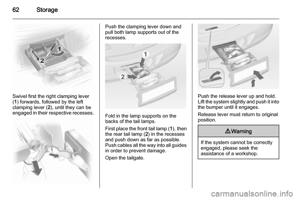
Swivel first the right clamping lever
( 1 ) forwards, followed by the left
clamping lever ( 2), until they can be
engaged in their respective recesses.
Push the clamping lever down and
pull both lamp supports out of the recesses.
Fold in the lamp supports on the
backs of the tail lamps.
First place the front tail lamp ( 1), then
the rear tail lamp ( 2) in the recesses
and push down as far as possible. Push cables all the way into all guides
in order to prevent damage.
Open the tailgate.
Push the release lever up and hold.
Lift the system slightly and push it into the bumper until it engages.
Release lever must return to original
position.
9 Warning
If the system cannot be correctly
engaged, please seek the
assistance of a workshop.
Page 66 of 231

64Storage
Move rear seat backrests upright and
allow locking mechanisms to engage
audibly at both sides. Once the
backrests are locked the red mark
must no longer protrude.
The rear seat backrests can be
locked in two positions.
Do not trap the seat belt when moving the backrest to the upright position.
Install the load compartment cover.
9 Warning
Only drive the vehicle when the
backrests are securely locked into position. Otherwise there is a risk
of personal injury or damage to the
load or vehicle in the event of hard braking or a collision.
The seat belt of the centre seat could
be blocked when the backrest is
folded up too quickly. To unlock the
retractor, push in the seat belt or pull
it out by approx. 20 mm and then let
go.
Load compartment cover
Do not place any objects on the cover.
5-door passenger vehicle
Lift the cover backwards, until it
unlatches, then remove.
Fit in reverse order.
Page 69 of 231

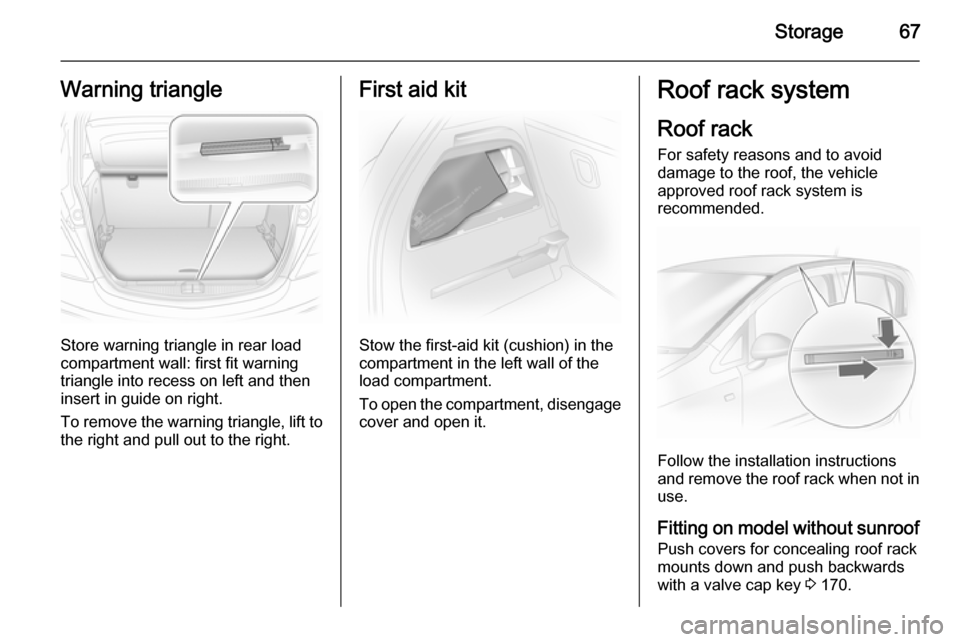
Storage67Warning triangle
Store warning triangle in rear load
compartment wall: first fit warning triangle into recess on left and then
insert in guide on right.
To remove the warning triangle, lift to
the right and pull out to the right.
First aid kit
Stow the first-aid kit (cushion) in the
compartment in the left wall of the
load compartment.
To open the compartment, disengage cover and open it.
Roof rack system
Roof rack For safety reasons and to avoid
damage to the roof, the vehicle
approved roof rack system is
recommended.
Follow the installation instructions
and remove the roof rack when not in
use.
Fitting on model without sunroof Push covers for concealing roof rackmounts down and push backwards
with a valve cap key 3 170.
Page 70 of 231

68Storage
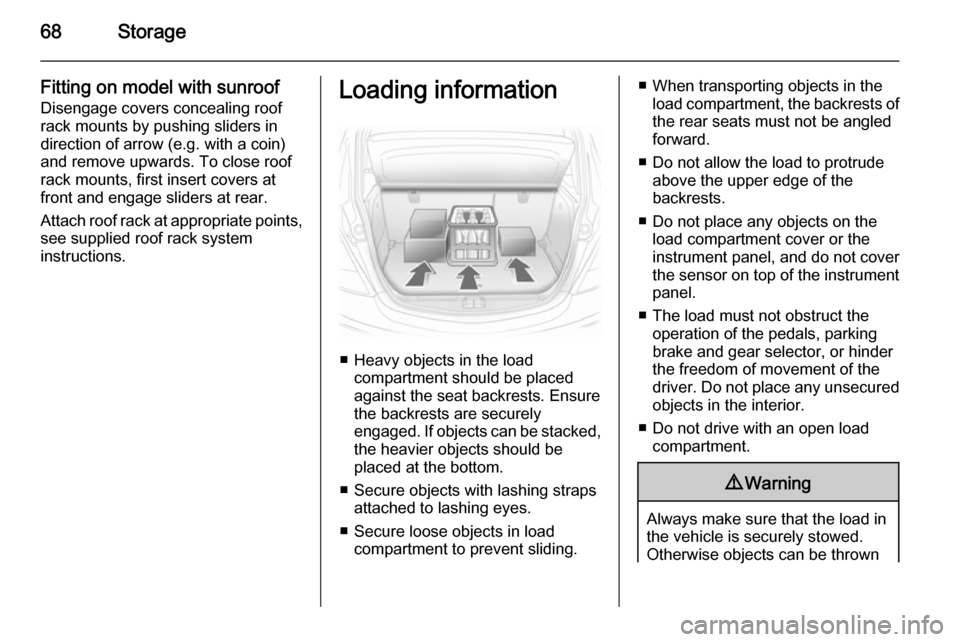
Fitting on model with sunroofDisengage covers concealing roof
rack mounts by pushing sliders in
direction of arrow (e.g. with a coin)
and remove upwards. To close roof
rack mounts, first insert covers at
front and engage sliders at rear.
Attach roof rack at appropriate points, see supplied roof rack system
instructions.Loading information
■ Heavy objects in the load compartment should be placedagainst the seat backrests. Ensure
the backrests are securely
engaged. If objects can be stacked, the heavier objects should be
placed at the bottom.
■ Secure objects with lashing straps attached to lashing eyes.
■ Secure loose objects in load compartment to prevent sliding.
■ When transporting objects in theload compartment, the backrests of
the rear seats must not be angled
forward.
■ Do not allow the load to protrude above the upper edge of the
backrests.
■ Do not place any objects on the load compartment cover or theinstrument panel, and do not cover
the sensor on top of the instrument panel.
■ The load must not obstruct the operation of the pedals, parking
brake and gear selector, or hinder
the freedom of movement of the
driver. Do not place any unsecured objects in the interior.
■ Do not drive with an open load compartment.9 Warning
Always make sure that the load in
the vehicle is securely stowed.
Otherwise objects can be thrown
Page 72 of 231

70Instruments and controlsInstruments and
controlsControls ....................................... 70
Warning lights, gauges and indi‐
cators ........................................... 76
Information displays .....................86
Vehicle messages ........................ 90
Trip computer ............................... 91
Vehicle personalisation ................95Controls
Steering wheel adjustment
Unlock lever, adjust steering wheel,
then engage lever and ensure it is fully locked.
Do not adjust steering wheel unless
vehicle is stationary and steering
wheel lock has been released.
Steering wheel controls
The Infotainment system and the
Info-Display can be operated via the
controls on the steering wheel.
Further information is available in the
Infotainment system manual.