ignition VAUXHALL CORSA 2014.5 Repair Manual
[x] Cancel search | Manufacturer: VAUXHALL, Model Year: 2014.5, Model line: CORSA, Model: VAUXHALL CORSA 2014.5Pages: 231, PDF Size: 6.8 MB
Page 168 of 231

166Vehicle care
Glovebox light, foot well light
1. Prise the lamp out with ascrewdriver.
2.Press bulb slightly towards spring
clip and remove.
3. Insert new bulb.
4. Install lamp.Electrical system
Fuses
Data on the replacement fuse must
match the data on the defective fuse.
There are three fuse boxes in the
vehicle:
■ in the front left of the engine compartment,
■ in left-hand drive vehicles: in the interior behind the light switch, or,
in right-hand drive vehicles: behind
the glovebox,
■ behind a cover on the left side of the
load compartment.
Before replacing a fuse, turn off the
respective switch and the ignition.
A blown fuse can be recognised by its melted wire. Do not replace the fuse
until the cause of the fault has been
remedied.
Some functions are protected by
several fuses.
Fuses may also be inserted without existence of a function.
Page 170 of 231

168Vehicle care
No.Circuit1Starter2Air conditioning system3Diesel fuel filter heater4Horn5Manual transmission auto‐
mated, automatic transmission6Engine control unit7Fog lights8Engine cooling9Engine cooling10Manual transmission auto‐
mated11Glow plugs, ignition system12Headlight range adjustment,
Adaptive forward lighting13Air conditioning system14Manual transmission auto‐
mated15High beam (right)No.Circuit16High beam (left)17Main relay18Engine control unit19Airbags20Main relay21Main relay22Central control unit23Tyre repair kit24Fuel pump25ABS26Heated rear window27ABS28Interior fan29Cigarette lighter30Air conditioning system31Power window (left)32Power window (right)No.Circuit33Heated exterior mirrors34–35–
Instrument panel fuse box
In left-hand drive vehicles, the fuse
box is behind the light switch. Pull the top edge of the panel and fold down.
Page 171 of 231

Vehicle care169
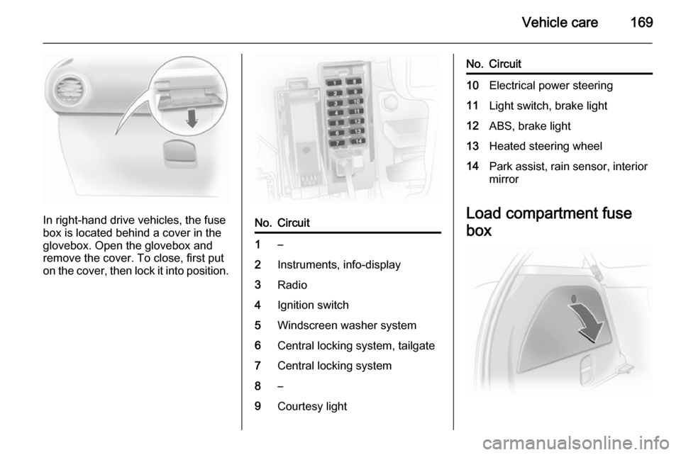
In right-hand drive vehicles, the fuse
box is located behind a cover in the
glovebox. Open the glovebox and
remove the cover. To close, first put
on the cover, then lock it into position.
No.Circuit1–2Instruments, info-display3Radio4Ignition switch5Windscreen washer system6Central locking system, tailgate7Central locking system8–9Courtesy lightNo.Circuit10Electrical power steering11Light switch, brake light12ABS, brake light13Heated steering wheel14Park assist, rain sensor, interior mirror
Load compartment fuse
box
Page 177 of 231

Vehicle care175
on your vehicle to ensure that the
replacement or alternate tyres and wheels allow the tyre pressure
monitoring system to continue to
function properly.
The use of commercially available
liquid tyre repair kits can impair the
function of the system. Factory
approved repair kits can be used.
System initialisation After a wheel change or tyre pressure
adjustment the system must be
initialised: inflate the cold tyres to the
prescribed pressure according to the
tyre information label or this
document 3 217. Then switch on
ignition and press and hold the DDS
button for approx. 4 seconds. The
control indicator A flashes three
times.
If the tyre pressure difference
between the left and the right wheel
on one axle is more than 30 kPa, tyre
pressure monitoring system
malfunction will be indicated, as the
vehicle starts moving for the first time after initialisation. Adjust tyre
pressure and repeat initialisation.Notice
The system needs to be initialised
after tyre pressure change,
otherwise it will not be able to warn
properly.
Each time the tyres are replaced, the
tyre pressure monitoring system
sensors have to be dismounted and
serviced. For the screwed sensor
replace the valve core and sealing
ring, for the clipped sensor replace
complete rubber valve stem.
Auto learn function
After changing wheels the vehicle
must be stationary for approx.
20 minutes, before the system
recalculates. The following relearn
process takes up to 10 minutes of
driving with a minimum speed of
16 mph.
Tyre deflation detection
system The tyre deflation detection system
continually checks the rotation speed
of all four tyres.
If a tyre loses pressure the control
indicator w illuminates red. Stop
immediately and check tyre pressure.
Control indicator w 3 83.
Page 178 of 231

176Vehicle care
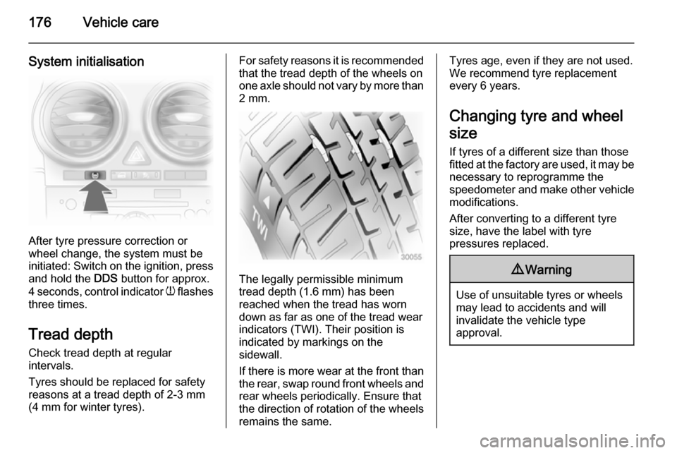
System initialisation
After tyre pressure correction or
wheel change, the system must be
initiated: Switch on the ignition, press and hold the DDS button for approx.
4 seconds, control indicator w flashes
three times.
Tread depth
Check tread depth at regular
intervals.
Tyres should be replaced for safety
reasons at a tread depth of 2-3 mm
(4 mm for winter tyres).
For safety reasons it is recommended
that the tread depth of the wheels on
one axle should not vary by more than 2 mm.
The legally permissible minimum
tread depth (1.6 mm) has been
reached when the tread has worn
down as far as one of the tread wear
indicators (TWI). Their position is
indicated by markings on the
sidewall.
If there is more wear at the front than
the rear, swap round front wheels and
rear wheels periodically. Ensure that
the direction of rotation of the wheels
remains the same.
Tyres age, even if they are not used.
We recommend tyre replacement
every 6 years.
Changing tyre and wheel
size If tyres of a different size than those
fitted at the factory are used, it may be necessary to reprogramme the
speedometer and make other vehicle
modifications.
After converting to a different tyre
size, have the label with tyre
pressures replaced.9 Warning
Use of unsuitable tyres or wheels
may lead to accidents and will
invalidate the vehicle type
approval.
Page 181 of 231

Vehicle care179
2. Detach air hose from bracket andscrew onto sealant bottle
connection.
3. Position the sealant bottle on the bracket. Make sure that the bottle
does not fall.
4. Unscrew valve cap from defective
tyre.
5. Screw tyre inflation hose to valve.
6. Screw air hose onto compressor connection.
7. Switch on ignition. To avoid discharging the battery,
we recommend running the
engine.8. Press on/off switch on the compressor. The tyre is filled withsealant.
9. The compressor pressure gauge briefly indicates up to 6 bar whilstthe sealant bottle is emptying
(approx. 30 seconds). Then the
pressure starts to drop.
10. All of the sealant is pumped into the tyre. Then the tyre is inflated.
11. The prescribed tyre pressure should be obtained within
10 minutes. Tyre pressure
3 217 . When the correct pressure
is obtained, switch off the
Page 191 of 231

Vehicle care189Towing
Towing the vehicle
Insert a suitable screwdriver in the
slot at the lower bend of the cap.
Release the cap by carefully moving
the screwdriver downwards.
Corsa VXR: Disengage and remove
cap by pressing on the lower part of
the cap.
The towing eye is stowed with the
vehicle tools 3 170 . The towing eye is
located in a recess.
Screw in the towing eye as far as it will
go until it stops in a horizontal
position.
Attach a tow rope – or better still a tow
rod – to the towing eye.
The towing eye must only be used for towing and not recovering the vehicle.
Switch on ignition to release steering
wheel lock and to permit operation of
brake lights, horn and windscreen
wiper.
Transmission in neutral.Caution
Drive slowly. Do not drive jerkily.
Excessive tractive force can
damage the vehicle.
When the engine is not running,
considerably more force is needed to
brake and steer.
To prevent the entry of exhaust gases from the towing vehicle, switch on the
air recirculation and close the
windows.
Page 197 of 231

Service and maintenance195
Fixed service intervalWhen service is due, InSP appears in
the odometer display for approx.
10 seconds when the ignition is
switched on. Have the next service performed by a workshop within
one week or 300 miles (whichever
occurs first).
Flexible service interval The service interval is based on
several parameters depending on
usage and calculated using these
parameters.
If the remaining distance is less than
1000 miles, InSP is displayed with a
remaining distance of 600 miles when
the ignition is switched on and off. If
less than 600 miles remain, InSP is
displayed for several seconds. Have
the next service performed by a
workshop within one week or
300 miles (whichever occurs first).Display of remaining distance:
1. Switch off ignition.
2. Briefly press the trip odometer reset button. The odometer
reading is shown.
3. Press and hold the reset button for
approx. 2 seconds. InSP and the
remaining distance are displayed.Recommended fluids,
lubricants and parts
Recommended fluids and lubricants Only use products that meet the
recommended specifications.
Damage resulting from the use of
products not in line with these
specifiations will not be covered by
the warranty.9 Warning
Operating materials are
hazardous and could be
poisonous. Handle with care. Pay
attention to information given on
the containers.
Engine oil
Engine oil is identified by its quality
and its viscosity. Quality is more
important than viscosity when
selecting which engine oil to use. The oil quality ensures e.g. engine
cleanliness, wear protection and oil
Page 225 of 231

Customer information223
■ Vehicle reactions in particulardriving situations (e.g. inflation of
an airbag, activation of the stability
regulation system)
■ Environmental conditions (e.g. temperature)
These data are exclusively technical
and help identifying and correcting
errors as well as optimizing vehicle
functions.
Motion profiles indicating travelled
routes cannot be created with these
data.
If services are used (e.g. repair
works, service processes, warranty cases, quality assurance),
employees of the service network
(manufacturer included) are able to
read out this technical information
from the event and error data storage
modules applying special diagnostic
devices. If required, you will receive
further information at these
workshops. After an error has been
corrected, the data are deleted from
the error storage module or they are
constantly overwritten.When using the vehicle, situations
may occur in which these technical
data related to other information
(accident report, damages on the
vehicle, witness statements etc.) may be associated with a specific person -
possibly, with the assistance of an
expert.
Additional functions contractually
agreed upon with the client (e.g.
vehicle location in emergency cases)
allow the transmission of particular vehicle data from the vehicle.Radio Frequency
Identification (RFID) RFID technology is used in somevehicles for functions such as tyre
deflation detection and ignition
system security. It is also used in
connection with conveniences such
as radio remote controls for door
locking/unlocking and starting, and in-
vehicle transmitters for garage door
openers. RFID technology in
Vauxhall vehicles does not use or
record personal information or link with any other Vauxhall system
containing personal information.
Page 228 of 231

226
Head restraint adjustment .............7
Head restraints ............................ 34
Heated mirrors ............................. 28
Heated rear window ..................... 31
Heated steering wheel .................71
Heating ........................................ 38
Heating and ventilation system . 106
High beam ............................. 85, 99
Hill start assist ........................... 130
Horn ....................................... 13, 71
I
Identification plate .....................197
Ignition switch positions .............115
Immobiliser .................................. 26
Indicators ...................................... 76
Information displays...................... 86
Instrument cluster ........................76
Instrument panel fuse box .........168
Instrument panel illumination control .................................... 103
Instrument panel overview ........... 10
Interior care ............................... 193
Interior lighting ............................ 103
Interior lights ...................... 103, 165
Interior mirrors .............................. 29
Interruption of power supply 122, 127
Introduction .................................... 3
Isofix child restraint systems ........ 52J
Jump starting ............................. 187
K Key, memorised settings ..............21
Keys ............................................. 19
Keys, locks ................................... 19
L
Lashing eyes ............................... 66
Lighting ........................................ 90
Lighting features .........................105
Light switch .................................. 98
Load compartment ................24, 63
Load compartment cover .............64
Load compartment fuse box ......169
Load compartment lighting .........104
Loading information .....................68
Low engine oil level .....................84
Low fuel ....................................... 84
M
Malfunction indicator light ............81
Manual anti-dazzle ......................29
Manual mode ............................. 125
Manual transmission .................. 123
Manual transmission automated 124
Manual windows ..........................30
Memorised settings ......................21Mirror adjustment ........................... 8
Misted light covers .....................103
N New vehicle running-in ..............115
Number plate light .....................164
O
Object detection systems ...........132
Odometer ..................................... 76
Oil, engine .......................... 195, 199
Outside temperature ....................73
Overrun cut-off ........................... 116
P Parking ................................ 18, 118
Parking assist ............................ 132
Parking brake ............................ 129
Parking lights ............................. 102
Particle filter ................................ 119
Performance .............................. 205
Performing work ........................146
Pollen filter ................................. 113
Power outlets ............................... 75
Power steering.............................. 82
Power windows ............................ 30
Preheating and diesel particle filter .......................................... 83
Puncture ..................................... 183