speed VAUXHALL CORSA F 2020 Repair Manual
[x] Cancel search | Manufacturer: VAUXHALL, Model Year: 2020, Model line: CORSA F, Model: VAUXHALL CORSA F 2020Pages: 227, PDF Size: 18.77 MB
Page 156 of 227

154Driving and operating9Warning
The system cannot replace the
need for vigilance on the part of
the driver. Taking a break is
recommended as soon as feeling tired or at least every 2 hours. Do
not drive when feeling tired.
Activation or Deactivation
The system can be activated or
deactivated in the vehicle
personalisation 3 76.
The state of the system stays in
memory when the ignition is switched
off.
Driving time alert
The driver gets notified by a pop-up reminder symbol € in the Driver
Information Centre simultaneously
with an acoustic alert if the driver has
not taken a break after 2 hours of
driving at a speed above 40 mph. The alert is repeated hourly until the
vehicle is stopped, no matter how
vehicle speed evolves.
The counting of driving time alert is
reset when the ignition has been
switched off for a few minutes.
Driver drowsiness detection The system monitors the driver's level
of vigilance at speeds above 40 mph.
A camera at the top of the windscreen detects variations in trajectory
compared to the lane markings.
If the trajectory of the vehicle
suggests a certain level of
drowsiness or inattention by the
driver, the system triggers the first
level of alert. The driver is notified by
a message and an audible signal is
given.
After three first level alerts, the
system triggers a new alert with a message, accompanied by a more
pronounced audible signal.
In certain driving conditions (poor
road surface or strong winds), the
system may give alerts independent
of the driver's level of vigilance.The driver drowsiness detection is
reinitialised when the ignition has
been switched off for a few minutes or the speed remains below 40 mph for
a few minutes.
System limitations
In the following situations, the system
may not operate properly or even not operate at all:
● poor visibility caused by inadequate lighting of the
roadway, falling snow, heavy
rain, dense fog etc.
● dazzle caused by headlamps of an oncoming vehicles, low sun,
reflections on damp roads,
leaving a tunnel, alternating
shade and light etc.
● windscreen area in front of the camera covered by dirt, snow,
stickers etc.
● no lane markings detected or multiple lane markings due to
roadworks
● close vehicles ahead
● winding roads or narrow roads
Page 160 of 227

158Driving and operatingTrailer hitch
General information
Only use towing equipment that has
been approved for your vehicle.
Entrust retrofitting of towing
equipment to a workshop. It may be
necessary to make changes that
affect the cooling system, heat
shields or other equipment.
The bulb outage detection function for trailer brake light cannot detect a
partial bulb outage. E.g. in case of
four bulbs with a power of 5 W each,
the function only detects lamp outage
when only a single 5 W lamp remains
or none remain.
Trailers equipped with LED lights are
not suitable for the wiring harness of
this trailer hitch.
Fitting of towing equipment could
cover the opening of the towing eye.
If this is the case, use the coupling ball
bar for towing. Always keep the
coupling ball bar in the vehicle to have
it on hand if needed.Driving characteristics and
towing tips
Before attaching a trailer, lubricate
the coupling ball. However, do not do
so if a stabiliser, which acts on the
coupling ball, is being used to reduce snaking movements.
During trailer towing do not exceed a
speed of 50 mph. A maximum speed
of 60 mph is only appropriate if an
oscillation damper is used and the
permissible gross trailer weight does
not exceed the vehicle’s curb weight.
For trailers with low driving stability
and caravan trailers, the use of an
oscillation damper is strongly
recommended.
If the trailer starts snaking, drive more
slowly, do not attempt to correct the
steering and brake sharply if
necessary.
When driving downhill, drive in the
same gear as if driving uphill and
drive at a similar speed.
Adjust tyre pressure to the value
specified for full load 3 208.Trailer towing
Trailer loadsThe permissible trailer loads are
vehicle and engine-dependent
maximum values which must not be
exceeded. The actual trailer load is
the difference between the actual
gross weight of the trailer and the
actual coupling socket load with the
trailer coupled.
The permissible trailer loads are
specified in the vehicle documents. In general, they are valid for gradients
up to 12%.
The permissible trailer load applies
up to the specified incline and at sea
level. Since engine power decreases
as altitude increases due to the air
becoming thinner, therefore reducing
climbing ability, the permissible gross
train weight also decreases by 10%
for every 1000 m of altitude. The
gross train weight does not have to be reduced when driving on roads with
slight inclines (less than 8%, e.g.
motorways).
Page 161 of 227

Driving and operating159The permissible gross train weight
must not be exceeded. This weight is
specified on the identification plate
3 201.
Vertical coupling load
The vertical coupling load is the load
exerted by the trailer on the coupling
ball. It can be varied by changing the
weight distribution when loading the
trailer.
The maximum permissible vertical
coupling load (55 kg) is specified on
the towing equipment identification
plate and in the vehicle documents.
Always aim for the maximum vertical
coupling load, especially in the case
of heavy trailers. The vertical coupling load should never fall below 25 kg.Rear axle load
When the trailer is coupled and the
towing vehicle fully loaded, the
permissible rear axle load (see
identification plate or vehicle
documents) may be exceeded by
60 kg , the gross vehicle weight rating
must not be exceeded. If the
permissible rear axle load is
exceeded, a maximum speed of
60 mph applies.
Page 179 of 227
Vehicle care177Vehicle tools
Tools
Vehicles with spare wheel
Open the load compartment.
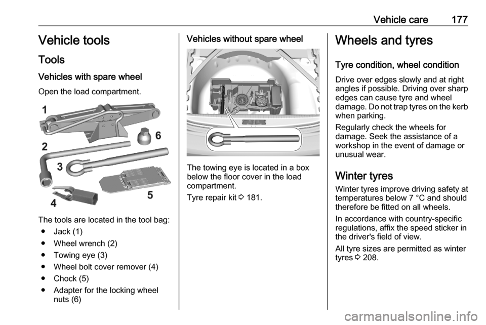
The tools are located in the tool bag: ● Jack (1)
● Wheel wrench (2)
● Towing eye (3)
● Wheel bolt cover remover (4)
● Chock (5)
● Adapter for the locking wheel nuts (6)
Vehicles without spare wheel
The towing eye is located in a box
below the floor cover in the load
compartment.
Tyre repair kit 3 181.
Wheels and tyres
Tyre condition, wheel condition Drive over edges slowly and at right
angles if possible. Driving over sharp
edges can cause tyre and wheel
damage. Do not trap tyres on the kerb when parking.
Regularly check the wheels for
damage. Seek the assistance of a
workshop in the event of damage or
unusual wear.
Winter tyres
Winter tyres improve driving safety at temperatures below 7 °C and should
therefore be fitted on all wheels.
In accordance with country-specific
regulations, affix the speed sticker in
the driver's field of view.
All tyre sizes are permitted as winter
tyres 3 208.
Page 180 of 227
178Vehicle careTyre designationsE.g. 225/55 R 18 98 V225:tyre width, mm55:cross-section ratio (tyre height
to tyre width), %R:belt type: RadialRF:type: RunFlat18:wheel diameter, inches98:load index e.g. 98 is equivalent
to 750 kgV:speed code letter
Speed code letter:
Q:up to 100 mphS:up to 112 mphT:up to 118 mphH:up to 130 mphV:up to 150 mphW:up to 168 mph
Choose a tyre appropriate for the
maximum speed of your vehicle.
The maximum speed is achievable at kerb weight with driver (75 kg) plus
125 kg payload. Optional equipment
could reduce the maximum speed of
the vehicle.
Performance 3 205.
Directional tyres
Directional tyres should be mounted
so that they rotate in the correct
direction. The proper rotation
direction is indicated by a symbol
(e.g. an arrow) on the sidewall.
Tyre pressure
Check the pressure of cold tyres at
least every 14 days and before any
long journey. Do not forget the spare
wheel. This also applies to vehicles
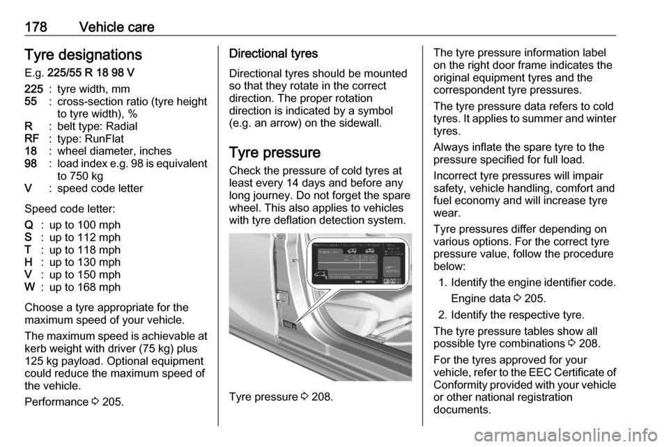
with tyre deflation detection system.
Tyre pressure 3 208.
The tyre pressure information label
on the right door frame indicates the original equipment tyres and the
correspondent tyre pressures.
The tyre pressure data refers to cold
tyres. It applies to summer and winter tyres.
Always inflate the spare tyre to the
pressure specified for full load.
Incorrect tyre pressures will impair
safety, vehicle handling, comfort and
fuel economy and will increase tyre
wear.
Tyre pressures differ depending on
various options. For the correct tyre
pressure value, follow the procedure
below:
1. Identify the engine identifier code.
Engine data 3 205.
2. Identify the respective tyre.
The tyre pressure tables show all
possible tyre combinations 3 208.
For the tyres approved for your
vehicle, refer to the EEC Certificate of Conformity provided with your vehicle
or other national registration
documents.
Page 181 of 227
Vehicle care179The driver is responsible for correct
adjustment of tyre pressure.9 Warning
If the pressure is too low, this can
result in considerable tyre warm-
up and internal damage, leading to tread separation and even to tyre
blow-out at high speeds.
9 Warning
For specific tyres the
recommended tyre pressure as
shown in the tyre pressure table may exceed the maximum tyre
pressure as indicated on the tyre.
Never exceed the maximum tyre
pressure as indicated on the tyre.
Temperature dependency
The tyre pressure depends on the
temperature of the tyre. During
driving, tyre temperature and
pressure increase. Tyre pressure
values provided on the tyre
information label and tyre pressure
chart are valid for cold tyres, which means at 20 °C.
The pressure increases by nearly
1.5 psi for a 10 °C temperature
increase. This must be considered
when warm tyres are checked.
Tyre deflation detectionsystem
The tyre deflation detection system
continually checks the rotation speed
of all four wheels and warns on low
tyre pressure condition once vehicle
is driving. This is achieved by
comparing tyre rolling circumference
with reference values and further
signals.
If a tyre loses pressure the control
indicator w illuminates and a warning
message is displayed in the Driver Information Centre.
Control indicator w 3 70.
In this case reduce speed, avoid
sharp cornering and strong braking.
Stop at next safe opportunity and
check tyre pressure.After adjusting tyre pressure initialise
system to extinguish the control
indicator and restart system.
If the failure continues to be
displayed, contact a workshop. The
system is inoperable when ABS or
ESC has a malfunction or a
temporary spare wheel is used. Once
the tyre has been refitted, check the
tyre pressure with cold tyres and
initialise the system.Caution
Deflation detection system warns
just about low tyre pressure
condition and does not replace
regular tyre maintenance by the
driver.
System initialisation
After tyre pressure correction or
wheel change, the system must be
initialised to learn new circumference
reference values:
Page 184 of 227
182Vehicle care
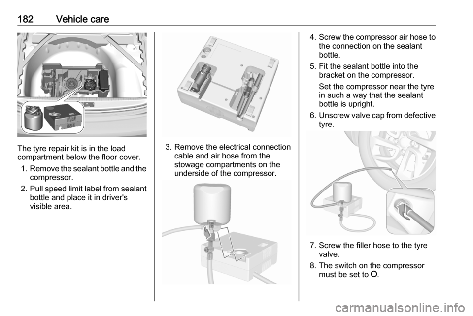
The tyre repair kit is in the load
compartment below the floor cover.
1. Remove the sealant bottle and the
compressor.
2. Pull speed limit label from sealant
bottle and place it in driver's
visible area.3. Remove the electrical connection cable and air hose from the
stowage compartments on the
underside of the compressor.
4. Screw the compressor air hose to
the connection on the sealant
bottle.
5. Fit the sealant bottle into the bracket on the compressor.
Set the compressor near the tyre
in such a way that the sealant
bottle is upright.
6. Unscrew valve cap from defective
tyre.
7. Screw the filler hose to the tyre valve.
8. The switch on the compressor must be set to J.
Page 188 of 227
186Vehicle careFront arm position of the lifting
platform centrically under the relevant vehicle jacking point.
Spare wheel
The spare wheel can be classified as
a temporary spare wheel depending
on the size compared to the other
mounted wheels and country
regulations. In this case a permissible maximum speed applies, even
though no label at the spare wheel
indicates this.
Only mount one temporary spare
wheel. Do not drive faster than
50 mph. Take curves slowly. Do not
use for a long period of time.Caution
The use of a spare wheel that is smaller than the other wheels or in combination with winter tyres
could affect driveability. Have the defective tyre replaced as soon as
possible.
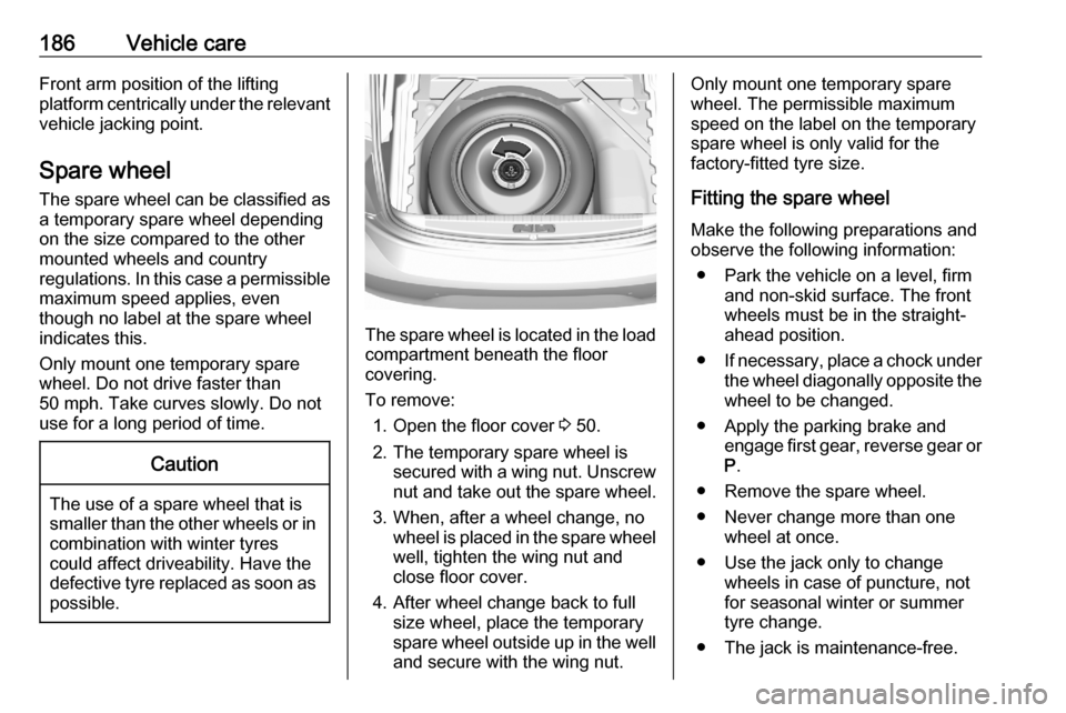
The spare wheel is located in the load
compartment beneath the floor
covering.
To remove: 1. Open the floor cover 3 50.
2. The temporary spare wheel is secured with a wing nut. Unscrew
nut and take out the spare wheel.
3. When, after a wheel change, no wheel is placed in the spare wheelwell, tighten the wing nut and
close floor cover.
4. After wheel change back to full size wheel, place the temporary
spare wheel outside up in the well
and secure with the wing nut.
Only mount one temporary spare
wheel. The permissible maximum
speed on the label on the temporary
spare wheel is only valid for the
factory-fitted tyre size.
Fitting the spare wheel
Make the following preparations and
observe the following information:
● Park the vehicle on a level, firm and non-skid surface. The front
wheels must be in the straight-
ahead position.
● If necessary, place a chock under
the wheel diagonally opposite the
wheel to be changed.
● Apply the parking brake and engage first gear, reverse gear or
P .
● Remove the spare wheel.
● Never change more than one wheel at once.
● Use the jack only to change wheels in case of puncture, not
for seasonal winter or summer
tyre change.
● The jack is maintenance-free.
Page 208 of 227
![VAUXHALL CORSA F 2020 Repair Manual 206Technical dataPerformanceEngineEB2FAEB2ADTDEB2ADTSDV5RDMaximum speed [mph]Manual transmission108117–117Automatic transmission–117129– VAUXHALL CORSA F 2020 Repair Manual 206Technical dataPerformanceEngineEB2FAEB2ADTDEB2ADTSDV5RDMaximum speed [mph]Manual transmission108117–117Automatic transmission–117129–](/img/38/19441/w960_19441-207.png)
206Technical dataPerformanceEngineEB2FAEB2ADTDEB2ADTSDV5RDMaximum speed [mph]Manual transmission108117–117Automatic transmission–117129–
Page 217 of 227

Customer information215Vehicle data recording
and privacy
Event data recorders Electronic control units are installed in
your vehicle. Control units process
data which is received by vehicle
sensors, for example, or which they
generate themselves or exchange
amongst themselves. Some control
units are necessary for the safe
functioning of your vehicle, others
assist you while you drive (driver
assistance systems), while others
provide comfort or infotainment
functions.
The following contains general
information about data processing in
the vehicle. You will find additional
information as to which specific data
is uploaded, stored and passed on to third parties and for what purpose in
your vehicle under the key word Data Protection closely linked to the
references for the affected functional
characteristics in the relevant owner's
manual or in the general terms of
sale. These are also available online.Operating data in the vehicle
Control units process data for
operation of the vehicle.
This data includes, for example: ● vehicle status information (e.g. speed, movement delay, lateral
acceleration, wheel rotation rate,
"seat belts fastened" display)
● ambient conditions (e.g. temperature, rain sensor,
distance sensor)
As a rule such data is transient and is not stored for longer than an
operational cycle, and only processed
on board the vehicle itself. Often
control units include data storage
(including the vehicle key). This is
used to allow information to be
documented temporarily or
permanently on vehicle condition,
component stress, maintenance
requirements and technical events
and errors.Depending on technical equipment
levels, the data stored is as follows:
● system component operating states (e.g. fill level, tyre
pressure, battery status)
● faults and defects in important system components (e.g. lights,
brakes)
● system reactions in special driving situations (e.g. triggeringof an airbag, actuation of the
stability control systems)
● information on events damaging the vehicle
● for electric vehicles the amount of
charge in the high-voltage
battery, estimated range
In special cases (e.g. if the vehicle
has detected a malfunction), it may be
necessary to save data that would
otherwise just be volatile.
When you use services (e.g. repairs,
maintenance), the operating data
saved can be read together with the
vehicle identification number and
used where necessary. Staff working
for the service network ( e.g. garages,
manufacturers) or third parties (e.g.