charging VAUXHALL CORSA F 2020 Owner's Manual
[x] Cancel search | Manufacturer: VAUXHALL, Model Year: 2020, Model line: CORSA F, Model: VAUXHALL CORSA F 2020Pages: 227, PDF Size: 18.77 MB
Page 9 of 227

In brief71Power windows .....................22
2 Exterior mirrors .....................20
3 Side air vents ........................ 95
4 Turn lights, headlight
flash, low/high beam, high
beam assist ........................... 84
Exit lighting ........................... 87
Parking lights ........................ 85
Buttons for Driver
Information Centre ................72
5 Cruise control .....................119
Speed limiter ....................... 121
Heated steering wheel ..........54
6 Instruments .......................... 62
Driver Information Centre ...... 72
7 Infotainment controls
8 Windscreen wiper and
washer, rear wiper and
washer ................................. 55
9 Power button ......................... 99
10 Central locking system ..........11
11 Centre air vents .................... 9512Controls for Info-Display
operation ............................... 74
13 Anti-theft alarm system
status LED ........................... 18
14 Info-Display .......................... 74
15 Hazard warning flashers ......84
16 Glovebox .............................. 46
17 Climate control system .......... 89
18 USB charging port ................ 58
19 Power outlet .......................... 58
20 Parking assist / Advanced
parking assist .....................137
Lane keep assist .................151
Stop start system ................102
Electronic Stability Control and Traction Control ...........117
21 Manual transmission ..........113
Automatic transmission ......109
22 Manual parking brake ........114
Electric parking brake ........114
23 Ignition switch ....................... 98
24 Steering wheel adjustment ..54
25 Horn ..................................... 5526Fuse box ............................ 175
27 Bonnet release lever ..........162
28 Light switch .......................... 79
Headlight range
adjustment ........................... 81
Front/rear fog lights ..............84
Instrument illumination .........86
Page 15 of 227
Keys, doors and windows13Electronic key system operationThis system allows automatic vehiclelocking and unlocking simply by
detection of the electronic key. The
electronic key must be outside the
vehicle.
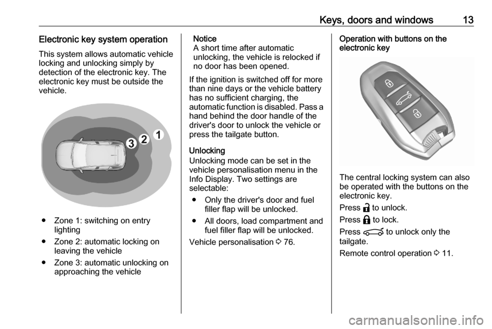
● Zone 1: switching on entry lighting
● Zone 2: automatic locking on leaving the vehicle
● Zone 3: automatic unlocking on approaching the vehicle
Notice
A short time after automatic
unlocking, the vehicle is relocked if
no door has been opened.
If the ignition is switched off for more than nine days or the vehicle battery
has no sufficient charging, the
automatic function is disabled. Pass a hand behind the door handle of the
driver's door to unlock the vehicle or
press the tailgate button.
Unlocking
Unlocking mode can be set in the
vehicle personalisation menu in the
Info Display. Two settings are
selectable:
● Only the driver's door and fuel filler flap will be unlocked.
● All doors, load compartment and fuel filler flap will be unlocked.
Vehicle personalisation 3 76.Operation with buttons on the
electronic key
The central locking system can also
be operated with the buttons on the
electronic key.
Press a to unlock.
Press b to lock.
Press ? to unlock only the
tailgate.
Remote control operation 3 11.
Page 55 of 227

Instruments and controls53Instruments and
controlsControls ....................................... 54
Steering wheel adjustment ........54
Steering wheel controls .............54
Heated steering wheel ...............54
Horn ........................................... 55
Windscreen wiper and washer ..55
Rear window wiper and washer ...................................... 57
Outside temperature ..................57
Clock ......................................... 58
Power outlets ............................. 58
Inductive charging .....................59
Cigarette lighter ......................... 60
Ashtrays .................................... 60
Warning lights, gauges and indi‐ cators ........................................... 61
Instrument cluster ......................61
Speedometer ............................. 62
Odometer .................................. 62
Trip odometer ............................ 62
Tachometer ............................... 63
Fuel gauge ................................ 63
Engine coolant temperature gauge ....................................... 63Engine oil level monitor.............64
Service display .......................... 64
Control indicators ......................65
Turn lights .................................. 65
Seat belt reminder .....................65
Airbag and belt tensioners .........66
Airbag deactivation ....................66
Charging system .......................66
Malfunction indicator light ..........67
Service vehicle soon .................67
Stop engine ............................... 67
System check ............................ 67
Brake and clutch system ...........67
Parking brake ............................ 68
Electric parking brake ................68
Electric parking brake fault ........68
Automatic operation of electric parking brake off ....................... 68
Antilock brake system (ABS) .....68
Gear shifting .............................. 69
Lane keep assist .......................69
Electronic Stability Control and Traction Control system ...........69
Engine coolant temperature ......69
Preheating ................................. 69
Exhaust filter .............................. 69
AdBlue ....................................... 70
Deflation detection system ........70
Engine oil pressure ....................70
Low fuel ..................................... 71Autostop.................................... 71
Exterior light .............................. 71
Low beam .................................. 71
High beam ................................. 71
High beam assist .......................71
LED headlights .......................... 71
Front fog lights ........................... 71
Rear fog light ............................. 71
Rain sensor ............................... 71
Active emergency braking .........72
Door open .................................. 72
Displays ....................................... 72
Driver Information Centre ..........72
Info Display ................................ 74
Vehicle messages ........................75
Warning chimes .........................76
Vehicle personalisation ................76
Telematics services .....................77
Vauxhall Connect ......................77
Page 60 of 227
58Instruments and controls9Warning
The road surface may already be
icy even though the display
indicates a few degrees above 0
°C.
Clock
Date and time are shown in the Info
Display.
The adjustment of date and time is
described in the Infotainment Manual.
Info Display 3 74.
Power outlets
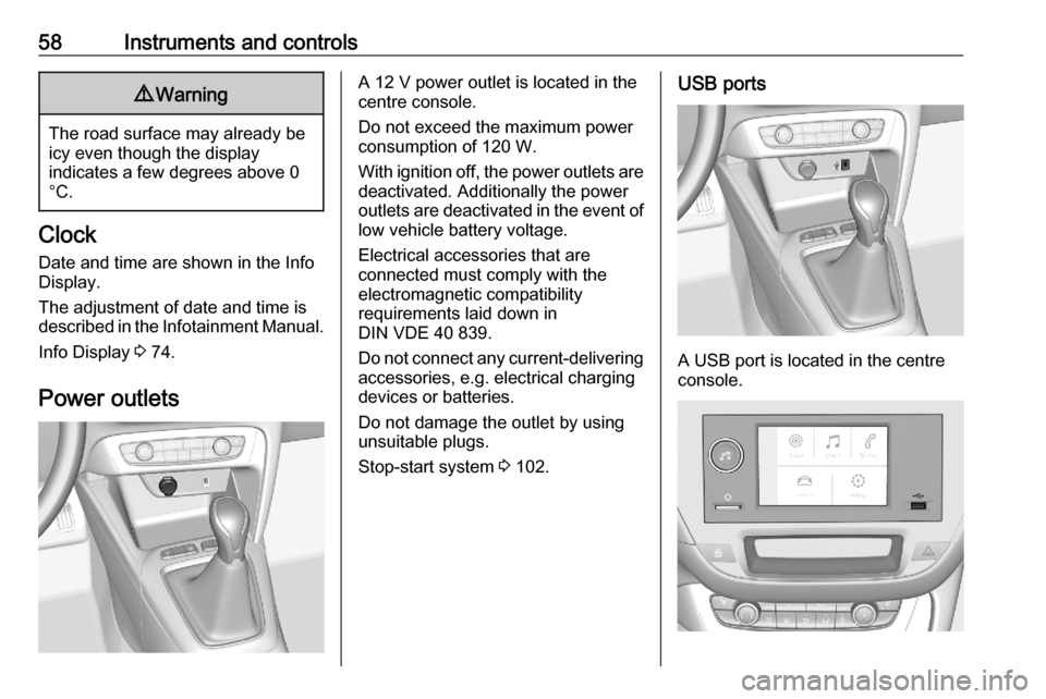
A 12 V power outlet is located in the
centre console.
Do not exceed the maximum power
consumption of 120 W.
With ignition off, the power outlets are
deactivated. Additionally the power
outlets are deactivated in the event of
low vehicle battery voltage.
Electrical accessories that are
connected must comply with the
electromagnetic compatibility
requirements laid down in
DIN VDE 40 839.
Do not connect any current-delivering
accessories, e.g. electrical charging
devices or batteries.
Do not damage the outlet by using
unsuitable plugs.
Stop-start system 3 102.USB ports
A USB port is located in the centre
console.
Page 61 of 227
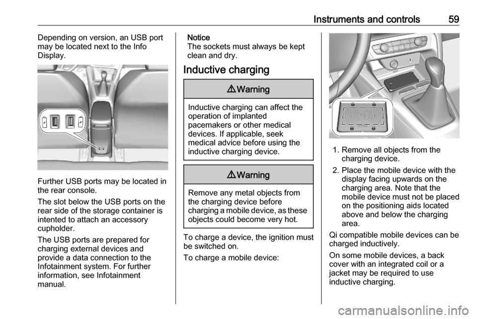
Instruments and controls59Depending on version, an USB port
may be located next to the Info
Display.
Further USB ports may be located in
the rear console.
The slot below the USB ports on the rear side of the storage container is
intented to attach an accessory
cupholder.
The USB ports are prepared for
charging external devices and
provide a data connection to the
Infotainment system. For further
information, see Infotainment
manual.
Notice
The sockets must always be kept
clean and dry.
Inductive charging9 Warning
Inductive charging can affect the
operation of implanted
pacemakers or other medical
devices. If applicable, seek
medical advice before using the
inductive charging device.
9 Warning
Remove any metal objects from
the charging device before
charging a mobile device, as these objects could become very hot.
To charge a device, the ignition must
be switched on.
To charge a mobile device:
1. Remove all objects from the charging device.
2. Place the mobile device with the display facing upwards on the
charging area. Note that the
mobile device must not be placed
on the positioning aids located
above and below the charging
area.
Qi compatible mobile devices can be
charged inductively.
On some mobile devices, a back
cover with an integrated coil or a
jacket may be required to use
inductive charging.
Page 62 of 227
60Instruments and controlsProtective cover for the mobile device
could have impact on the inductive
charging.
In the event that the mobile device is
not charging properly, rotate it 180°
and place it on the charging device
again.
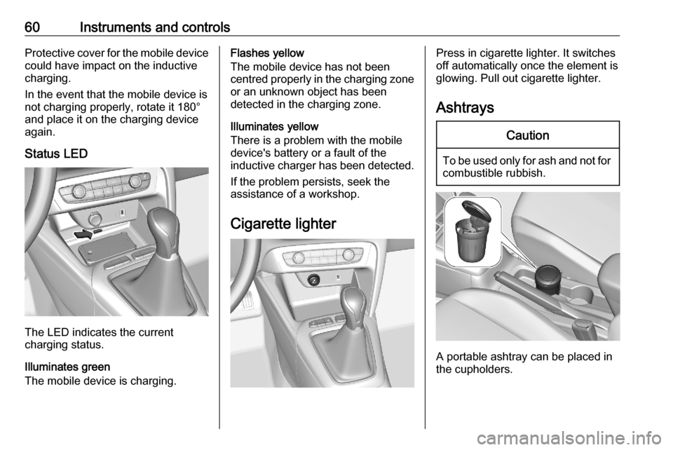
Status LED
The LED indicates the current
charging status.
Illuminates green
The mobile device is charging.
Flashes yellow
The mobile device has not been
centred properly in the charging zone
or an unknown object has been
detected in the charging zone.
Illuminates yellow
There is a problem with the mobile
device's battery or a fault of the
inductive charger has been detected.
If the problem persists, seek the
assistance of a workshop.
Cigarette lighterPress in cigarette lighter. It switches
off automatically once the element is
glowing. Pull out cigarette lighter.
AshtraysCaution
To be used only for ash and not for combustible rubbish.
A portable ashtray can be placed in
the cupholders.
Page 63 of 227
Instruments and controls61Warning lights, gauges
and indicators
Instrument cluster
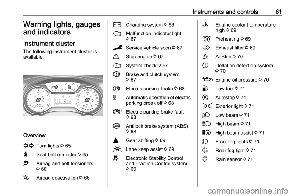
The following instrument cluster is
available:
Overview
1Turn lights 3 65aSeat belt reminder 3 65dAirbag and belt tensioners
3 66gAirbag deactivation 3 66SCharging system 3 66WMalfunction indicator light
3 67CService vehicle soon 3 67+Stop engine 3 67XSystem check 3 67hBrake and clutch system
3 67j ,Electric parking brake 3 68oAutomatic operation of electric
parking break off 3 68kElectric parking brake fault
3 68iAntilock brake system (ABS)
3 68YGear shifting 3 69LLane keep assist 3 69JElectronic Stability Control
and Traction Control system
3 69VEngine coolant temperature
high 3 69zPreheating 3 69tExhaust filter 3 69uAdBlue 3 70qDeflation detection system
3 70TEngine oil pressure 3 70rLow fuel 3 71nAutostop 3 71FExterior light 3 71DLow beam 3 71AHigh beam 3 71BHigh beam assist 3 71GFront fog lights 3 71HRear fog light 3 71yRain sensor 3 71
Page 68 of 227
66Instruments and controls
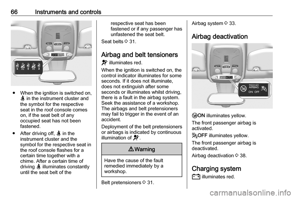
●When the ignition is switched on,
a in the instrument cluster and
the symbol for the respective
seat in the roof console comes
on, if the seat belt of any
occupied seat has not been
fastened.
● After driving off, a in the
instrument cluster and the
symbol for the respective seat in
the roof console flashes for a
certain time together with a
chime. After a certain time of
driving a illuminates constantly
until the seat belt of the
respective seat has been
fastened or if any passenger has
unfastened the seat belt.
Seat belts 3 31.
Airbag and belt tensioners d illuminates red.
When the ignition is switched on, the
control indicator illuminates for some
seconds. If it does not illuminate,
does not extinguish after some
seconds or illuminates whilst driving,
there is a fault in the airbag system.
Seek the assistance of a workshop.
The airbags and belt pretensioners
may fail to trigger in the event of an
accident.
Deployment of the belt pretensioners
or airbags is indicated by continuous
illumination of d.9Warning
Have the cause of the fault
remedied immediately by a
workshop.
Belt pretensioners 3 31.
Airbag system 3 33.
Airbag deactivation
H ON illuminates yellow.
The front passenger airbag is
activated.
g OFF illuminates yellow.
The front passenger airbag is
deactivated.
Airbag deactivation 3 38.
Charging system
S illuminates red.
Page 69 of 227

Instruments and controls67Illuminates when the ignition is
switched on and extinguishes shortly after the engine starts.
Illuminates when the engine is
running
Stop, switch off engine. Vehicle
battery is not charging. Engine
cooling may be interrupted. The
brake servo unit may cease to be effective. Seek the assistance of a
workshop.
Malfunction indicator light W illuminates or flashes yellow.
Illuminates when the ignition is
switched on and extinguishes shortly
after the engine starts.
Illuminates when the engine is
running
Fault in the emission control system. The permitted emission limits may be exceeded. Seek the assistance of a
workshop immediately.Flashes when the engine is
running
Fault that could lead to catalyticconverter damage. Ease up on the accelerator until the flashing stops.
Seek the assistance of a workshop
immediately.
Service vehicle soon
C illuminates yellow.
Illuminates briefly when the ignition is switched on.
May illuminate together with other
control indicators and a
corresponding message in the Driver
Information Centre.
Seek the assistance of a workshop
immediately.
Stop engine
+ illuminates red.
Illuminates briefly when the ignition is
switched on.Illuminates together with other control indicators, accompanied by a warning
chime and a corresponding message in the Driver Information Centre.
Stop engine immediately and seek
the assistance of a workshop.
System check X illuminates yellow or red.
Illuminates yellow A minor engine fault has been
detected.
Illuminates red A major engine fault has been
detected.
Stop engine as soon as possible and seek the assistance of a workshop.
Brake and clutch systemh illuminates red.
The brake and clutch fluid level is too
low.
Page 106 of 227

104Driving and operatingPower saving measures
During an Autostop, several electrical
features such as auxiliary electric
heater or rear window heating are
disabled or switched to a power
saving mode. The fan speed of the
climate control system is reduced to
save power.
Restart of the engine by the driver
Vehicles with manual transmission
Depress the clutch pedal without
depressing the brake pedal to restart
the engine.
Vehicles with automatic transmission The engine is restarted in the
following cases:
● brake pedal released while the selector lever in position D or M
● brake pedal released or selector lever in position N when selector
lever is moved to position D or
M
● selector lever moved to position RRestart of the engine by the stop-
start system
The selector lever must be in neutral to enable an automatic restart.
If one of the following conditions occurs during an Autostop, the
engine will be restarted automatically by the stop-start system:
● stop-start system manually deactivated
● driver's seat belt unfastened and driver's door opened
● engine temperature too low
● charging level of vehicle battery below a defined level
● brake vacuum not sufficient
● vehicle driven at least at walking speed
● climate control system requests engine start
● air conditioning manually switched on
If an electrical accessory, e.g. a
portable CD player, is connected to
the power outlet, a brief power drop
during the restart might be noticeable.Parking9 Warning
● Do not park the vehicle on an
easily ignitable surface. The
high temperature of the
exhaust system could ignite the
surface.
● Always apply the parking brake.
● If the vehicle is on a level surface or uphill slope, engage
first gear or set the selector
lever to position P. On an uphill
slope, turn the front wheels
away from the kerb.
If the vehicle is on a downhill
slope, engage reverse gear or
set the selector lever to position
P . Turn the front wheels
towards the kerb.
● Close the windows.
● Switch off the engine.
● Remove the ignition key from the ignition switch or switch off
ignition on vehicles with power