engine VAUXHALL CROSSLAND X 2018.5 Workshop Manual
[x] Cancel search | Manufacturer: VAUXHALL, Model Year: 2018.5, Model line: CROSSLAND X, Model: VAUXHALL CROSSLAND X 2018.5Pages: 259, PDF Size: 7.9 MB
Page 145 of 259

Driving and operating143P:park position, wheels are locked,
engage only when the vehicle is
stationary and the parking brake is appliedR:reverse gear, engage only when
the vehicle is stationaryN:neutralD:automatic modeM:manual mode<:upshift in manual mode]:downshift in manual mode
The selector lever is locked in P and
can only be moved when the ignition is on and the brake pedal is applied.
The engine can only be started with the lever in position P or N. When
position N is selected, press the brake
pedal or apply the parking brake
before starting.
Do not accelerate while engaging a
gear. Never depress the accelerator
pedal and brake pedal at the same
time.
When a gear is engaged, the vehicle
slowly begins to creep when the
brake is released.
Engine braking
To utilise the engine braking effect, select a lower gear in good time when driving downhill, see manual mode.
Rocking the vehicle Rocking the vehicle is only
permissible if the vehicle is stuck in
sand, mud or snow. Move the selector
lever between D and R in a repeat
pattern. Do not race the engine and
avoid sudden acceleration.
Parking
Apply the parking brake and engage
P .Manual mode
Move selector lever out of position D
towards the left in position M.
Tap selector lever upwards + to shift
to a higher gear.
Tap the selector lever downwards - to
shift to a lower gear.
If a higher gear is selected when
vehicle speed is too low, or a lower
gear when vehicle speed is too high,
the shift is not executed. This can
cause a message in the Driver
Information Centre.
Page 146 of 259

144Driving and operatingIn manual mode, no automatic
shifting to a higher gear takes place
at high engine revolutions.
Gear shift indication
R with the number of a higher gear is
indicated, when upshifting is
recommended for fuel saving
reasons.
Shift indication appears only in
manual mode.
Electronic driving programmes
● Following a cold start, the operating temperature
programme increases engine
speed to quickly bring the
catalytic converter to the required
temperature.
● Special programmes automatically adapt the shifting
points when driving up inclines or
down hills.
● In snowy or icy conditions or on other slippery surfaces, the
electronic transmission controlenables the driver to select
manually first, second or third
gear for starting off.
Kickdown
Pressing down the accelerator pedal
beyond the kickdown detent will lead to maximum acceleration
independent of selected driving
mode. The transmission shifts to a lower gear depending on enginespeed.
Fault
In the event of a fault a message is
displayed in the Driver Information Centre. Vehicle messages 3 99.
Electronic transmission control
enables only third gear. The
transmission no longer shifts
automatically.
Do not drive faster than 62 mph. Have the cause of the fault remedied
by a workshop.Interruption of power supply
In the event of an interruption of
power supply, the selector lever
cannot be moved out of the P
position. The ignition key cannot be
removed from the ignition switch.
If the vehicle battery is discharged,
start the vehicle using jump leads
3 218.
If the vehicle battery is not the cause
of the fault, release the selector lever.
1. Apply the parking brake.
2. Release the selector lever trim from the centre console. Poke
with a finger into the leather
socket below the selector lever
and push the trim upwards.
Page 148 of 259
146Driving and operatingWhen clutch slip is detected for a
specific time, the engine power will be
reduced. A warning is displayed in the Driver Information Centre. Release
the clutch.Caution
It is not advisable to drive with the hand resting on the selector lever.
Gear shift indication 3 90.
Stop-start system 3 135.
Brakes
The brake system comprises two
independent brake circuits.
If a brake circuit fails, the vehicle can
still be braked using the other brake
circuit. However, braking effect is
achieved only when the brake pedal
is depressed firmly. Considerably
more force is needed for this. The
braking distance is extended. Seek
the assistance of a workshop before
continuing the journey.
When the engine is not running, the
support of the brake servo unit
disappears once the brake pedal has been depressed once or twice.
Braking effect is not reduced, but
braking requires significantly greater
force. It is especially important to bear this in mind when being towed.
Control indicator R 3 89.
Antilock brake system
Antilock brake system (ABS)
prevents the wheels from locking.ABS starts to regulate brake pressure as soon as a wheel shows a tendency to lock. The vehicle remains
steerable, even during hard braking.
ABS control is made apparent
through a pulse in the brake pedal
and the noise of the regulation
process.
For optimum braking, keep the brake
pedal fully depressed throughout the
braking process, despite the fact that
the pedal is pulsating. Do not reduce
the pressure on the pedal.
When braking in an emergency, the
hazard warning flashers are switched
on automatically depending on the
force of deceleration. They are
switched off automatically the first
time you accelerate.
After starting off, the system performs
a self-test which may be audible.
Control indicator u 3 90.
Page 150 of 259
148Driving and operatingRide control systems
Electronic Stability Control and Traction Control system
Electronic Stability Control (ESC)
improves driving stability when
necessary, regardless of the type of
road surface or tyre grip.
As soon as the vehicle starts to
swerve (understeer / oversteer),
engine output is reduced and the wheels are braked individually.
ESC operates in combination with the Traction Control system (TC). It
prevents the driven wheels from
spinning.
The TC is a component of the ESC.
TC improves driving stability when
necessary, regardless of the type of
road surface or tyre grip, by
preventing the driven wheels from
spinning.
As soon as the driven wheels starts to spin, engine output is reduced and
the wheel spinning the most is brakedindividually. This considerably
improves the driving stability of the
vehicle on slippery road surfaces.
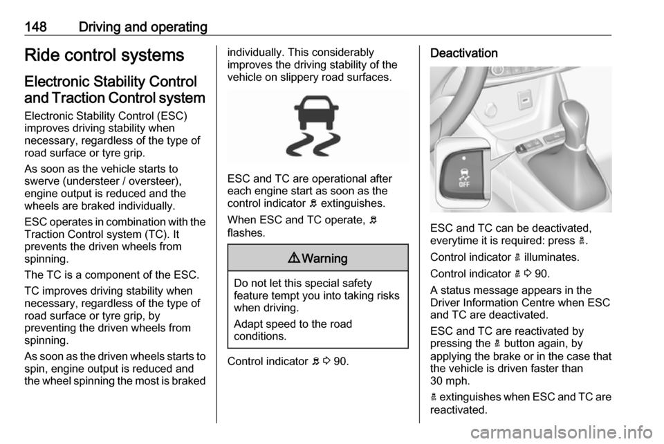
ESC and TC are operational after
each engine start as soon as the
control indicator b extinguishes.
When ESC and TC operate, b
flashes.
9 Warning
Do not let this special safety
feature tempt you into taking risks
when driving.
Adapt speed to the road
conditions.
Control indicator b 3 90.
Deactivation
ESC and TC can be deactivated,
everytime it is required: press a.
Control indicator a illuminates.
Control indicator a 3 90.
A status message appears in the
Driver Information Centre when ESC
and TC are deactivated.
ESC and TC are reactivated by
pressing the a button again, by
applying the brake or in the case that
the vehicle is driven faster than
30 mph.
a extinguishes when ESC and TC are
reactivated.
Page 159 of 259
Driving and operating157Emergency automatic braking may
slow the vehicle to a complete stop to
try to avoid a potential crash.9 Warning
Emergency automatic braking is
an emergency crash preparation
feature and is not designed to
avoid crashes. Do not rely on the
system to brake the vehicle.
Emergency automatic braking will
not brake outside of its operating speed range and only responds to
detected vehicles and
pedestrians.
Forward looking brake assist
In addition to emergency automatic
braking, the forward looking brake
assist function makes the brake assist more sensitive. Therefore, pressing
the brake pedal less strongly results in immediate hard braking. This
function helps the driver brake
quicker and harder before the
imminent collision.
9 Warning
Active emergency braking is not
designed to apply hard
autonomous braking or to
automatically avoid a collision. It is designed to reduce the vehicle
speed before a collision. It may not
react to animals. After a sudden
lane change, the system needs a
certain time to detect the next
preceding vehicle.
The complete attention of the
driver is always required while
driving. The driver must always be
ready to take action and apply the brakes and steer to avoid
collisions.
The system is designed to work with
all occupants wearing their seat belts.
Forward collision alert
3 154.
Front pedestrian protection
3 158.
Deactivation
Active emergency braking can bedeactivated in the personalisation
menu 3 100. If deactivated, m
illuminates in the instrument cluster
and a warning message is displayed
in the Driver Information Centre.
We recommend to deactivate the
system in the vehicle personalisation
in the following cases:
● when towing a trailer or caravan
● when carrying long objects on roof bars or a roof rack
● when the vehicle is being towed with the engine running
● when a spare wheel is fitted that is smaller than the other wheels
● before using an automatic car wash with the engine running
● before placing the vehicle on a rolling road in a workshop
● if the windscreen has been damaged close to the camera
● if the front bumper has been damaged
● if the brake lamps are not working
Page 168 of 259

166Driving and operatingDisplay indication
The instructions on the display show: ● General hints and warning messages.
● The demand to stop the vehicle, when a parking slot is detected.
● The direction of driving during the
parking manoeuvre.
● The demand to shift into reverse or first gear.
● The demand to stop or to drive slowly.
● The successful completion of the
parking manoeuvre indicated by
a pop-up symbol and a chime.
● The cancelling of a parking manoeuvre.
Deactivation The current park assist manoeuvre is
cancelled via the button to return to
the previous screen in the Colour Info Display. To deactivate the system
completely, press r Off in the
centre console.The system is deactivated
automatically:
● if the ignition is switched off
● if stalling the engine
● if no manoeuvre is started within 5 minutes of selection of the typeof manoeuvre
● after a prolonged stop of the vehicle during a manoeuvre
● if the electronic stability control (ESC) is triggered
● if the speed of the vehicle exceeds the stated limit
● when the driver interrupts movement of the steering wheel
● after 4 manoeuvre cycles
● on opening the driver's door
● if one of the front wheels encounters an obstacle
● parking manoeuvre successfully ended
Deactivation by the driver or by the system during manoeuvring will be
indicated on the display. Additionally, an acoustic signal sounds.The system is switched off
automatically when towing a
electrically connected trailer.
Contact your dealer to switch off the
system for a prolonged period.
Fault
In the event of a fault, $ flashes for a
few seconds, accompanied by an
acoustic signal. If the fault occurs
during the use of the system, $
extinguishes.
In the event of a fault in the power
steering, c flashes in the instrument
panel, accompanied by a message.9 Warning
Under certain circumstances,
various reflective surfaces on
objects or clothing as well as
external noise sources may cause the system to fail to detect
obstacles.
Special attention must be paid to
low obstacles which can damage
the lower part of the bumper.
Page 177 of 259

Driving and operating175level of alert. The driver is notified by
a message and an audible signal is
given.
After three first level alerts, the
system triggers a new alert with a
message, accompanied by a more
pronounced audible signal.
In certain driving conditions (poor
road surface or strong winds), the
system may give alerts independent of the driver's level of vigilance.
The driver drowsiness detection is reinitialised when the ignition hasbeen switched off for a few minutes or
the speed remains below 40 mph for
a few minutes.
System limitationsIn the following situations, the system
may not operate properly or even not
operate at all:
● Poor visibility caused by inadequate lighting of the
roadway, falling snow, heavy
rain, dense fog etc.● Dazzle caused by headlamps of an oncoming vehicles, low sun,
reflections on damp roads,
leaving a tunnel, alternating
shade and light etc.
● Windscreen area in front of the camera covered by dirt, snow,
stickers etc.
● No lane markings detected or multiple lane markings due to
roadworks
● Close vehicles ahead
● Winding roads or narrow roadsFuel
Fuel for petrol engines
The petrol engines are compatible
with bio-fuels that conform to current
and future European standards and
and can be obtained from filling
stations:
Petrol that meets the EN228
standard, mixed with a biofuel
meeting the EN15376 standard.
Notice
The only petrol additives authorised for use are those that meet the
B715001 standard.
Fuel for diesel engines
The Diesel engines are compatible
with bio-fuels that conform to current
and future European standards and
and can be obtained from filling
stations:
Page 178 of 259
176Driving and operating
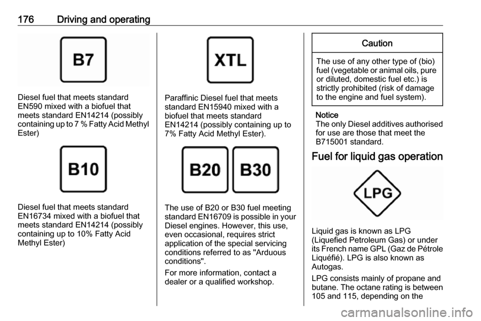
Diesel fuel that meets standard
EN590 mixed with a biofuel that
meets standard EN14214 (possibly
containing up to 7 % Fatty Acid Methyl Ester)
Diesel fuel that meets standard
EN16734 mixed with a biofuel that
meets standard EN14214 (possibly
containing up to 10% Fatty Acid
Methyl Ester)
Paraffinic Diesel fuel that meets
standard EN15940 mixed with a
biofuel that meets standard
EN14214 (possibly containing up to 7% Fatty Acid Methyl Ester).
The use of B20 or B30 fuel meetingstandard EN16709 is possible in your
Diesel engines. However, this use,
even occasional, requires strict
application of the special servicing
conditions referred to as "Arduous
conditions".
For more information, contact a
dealer or a qualified workshop.
Caution
The use of any other type of (bio)
fuel (vegetable or animal oils, pure
or diluted, domestic fuel etc.) is
strictly prohibited (risk of damage
to the engine and fuel system).
Notice
The only Diesel additives authorised for use are those that meet the
B715001 standard.
Fuel for liquid gas operation
Liquid gas is known as LPG
(Liquefied Petroleum Gas) or under its French name GPL (Gaz de Pétrole Liquéfié). LPG is also known as
Autogas.
LPG consists mainly of propane and
butane. The octane rating is between
105 and 115, depending on the
Page 182 of 259
180Driving and operatingEURO adapter: Press the filler nozzle
onto the adapter. Engage the locking
lever of the filler nozzle.
Press the button of the liquid gas
supply point. The filling system stops
or begins to run slowly when 80% of
the tank volume is reached
(maximum fill level).
Release button on filling system to stop the filling process. Release the
locking lever and remove the filler
nozzle. A small quantity of liquid gas
can escape.
Remove adapter and stow in vehicle.
Fit protective cap to prevent the
penetration of foreign bodies into the
filler opening and the system.9 Warning
Due to the system design, an
escape of liquid gas after
releasing the locking lever is
unavoidable. Avoid inhaling.
9 Warning
The liquid gas tank may only be
filled to 80% for safety reasons.
The multivalve on the liquid gas tank
automatically limits the fill quantity. If
a larger quantity is added, we
recommend not exposing the vehicle
to the sun until the excess amount
has been used up.
Twelve minutes after switching off the ignition the system of the fuel-filling
turns off. To restart it turn the ignition
on and then off again.
Fuel filler cap Only use genuine fuel filler caps.Diesel-engined vehicles have special
fuel filler caps.
Trailer hitch
General information
The factory-fitted towing equipment is
folded up under the rear bumper
fascia.
Entrust retrofitting of towing
equipment to a workshop. It may be
necessary to make changes that
affect the cooling system, heat
shields or other equipment. Only use
towing equipment that has been
approved for your vehicle.
To avoid vehicle damage, the power
tailgate cannot be operated with the
radio remote control when a trailer is
electrically connected.
The bulb outage detection function for trailer brake light cannot detect a
partial bulb outage. E.g. in case of
four bulbs with a power of 5 W each,
the function only detects lamp outage
when only a single 5 W lamp remains
or none remain.
Fitting of towing equipment could
cover the opening of the towing eye.
If this is the case use the coupling ball
bar for towing.
Page 183 of 259

Driving and operating181Driving characteristics and
towing tips
Before attaching a trailer, lubricate
the coupling ball. However, do not do
so if a stabiliser, which acts on the
coupling ball, is being used to reduce snaking movements.
During trailer towing do not exceed a
speed of 50 mph. A maximum speed
of 60 mph is only appropriate if an
oscillation damper is used and the
permissible gross trailer weight does
not exceed the vehicle's curb weight.
For trailers with low driving stability
and caravan trailers, the use of an
oscillation damper is strongly
recommended.
If the trailer starts snaking, drive more slowly, do not attempt to correct the
steering and brake sharply if
necessary.
When driving downhill, drive in the
same gear as if driving uphill and
drive at a similar speed.
Adjust tyre pressure to the value
specified for full load 3 240.Trailer towing
Trailer loadsThe permissible trailer loads are
vehicle and engine-dependent
maximum values which must not be
exceeded. The actual trailer load is the difference between the actual
gross weight of the trailer and the
actual coupling socket load with the
trailer coupled.
The permissible trailer loads are
specified in the vehicle documents. In general, they are valid for gradients
up to 12%.
The permissible trailer load applies
up to the specified incline and at sea
level. Since engine power decreases
as altitude increases due to the air
becoming thinner, therefore reducing
climbing ability, the permissible gross
train weight also decreases by 10%
for every 1000 m of altitude. The
gross train weight does not have to be reduced when driving on roads with
slight inclines (less than 8%, e.g.
motorways).The permissible gross train weight
must not be exceeded. This weight is
specified on the identification plate
3 229.
Vertical coupling load
The vertical coupling load is the load
exerted by the trailer on the coupling
ball. It can be varied by changing the
weight distribution when loading the
trailer.
The maximum permissible vertical
coupling load of 50 kg is specified on
the towing equipment identification
plate and in the vehicle documents.
Always aim for the maximum load,
especially in the case of heavy
trailers. The vertical coupling load
should never fall below 25 kg.