towing VAUXHALL GRANDLAND X 2018 User Guide
[x] Cancel search | Manufacturer: VAUXHALL, Model Year: 2018, Model line: GRANDLAND X, Model: VAUXHALL GRANDLAND X 2018Pages: 263, PDF Size: 7.41 MB
Page 199 of 263

Driving and operating197Trailer hitch
General information
Only use towing equipment that has
been approved for your vehicle.
Vehicles with natural gas engines
require special towing equipment.
Entrust retrofitting of towing
equipment to a workshop. It may be
necessary to make changes that
affect the cooling system, heat
shields or other equipment.
The bulb outage detection function for trailer brake light cannot detect a
partial bulb outage. E.g. in case of
4x 5 Watt bulbs, the function only
detects lamp outage when only a
single 5 Watt lamp remains or none
remain.
Fitting of towing equipment could
cover the opening of the towing eye.
If this is the case use the coupling ball
bar for towing. Always keep the
coupling ball bar in the vehicle.Driving characteristics and
towing tips
Before attaching a trailer, lubricate
the coupling ball. However, do not do
so if a stabiliser, which acts on the
coupling ball, is being used to reduce snaking movements.
During trailer towing do not exceed a speed of 50 mph. A maximum speed
of 60 mph is only appropriate if an oscillation damper is used and the
permissible gross trailer weight does
not exceed the vehicle's curb weight.
For trailers with low driving stability
and caravan trailers, the use of an
oscillation damper is strongly
recommended.
If the trailer starts snaking, drive more
slowly, do not attempt to correct the
steering and brake sharply if
necessary.
When driving downhill, drive in the
same gear as if driving uphill and
drive at a similar speed.
Adjust tyre pressure to the value
specified for full load 3 247.Trailer towing
Trailer loads
The permissible trailer loads are
vehicle and engine-dependent
maximum values which must not be exceeded. The actual trailer load is
the difference between the actual
gross weight of the trailer and the
actual coupling socket load with the
trailer coupled.
The permissible trailer loads are
specified in the vehicle documents. In general, they are valid for gradients
up to 12%.
The permissible trailer load applies
up to the specified incline and at sea
level. Since engine power decreases
as altitude increases due to the air becoming thinner, therefore reducing
climbing ability, the permissible gross
train weight also decreases by 10%
for every 1000 metres of altitude. The gross train weight does not have to be reduced when driving on roads with
slight inclines (less than 8%, e.g.
motorways).
Page 200 of 263
198Driving and operatingThe permissible gross train weight
must not be exceeded. This weight is
specified on the identification plate
3 238.
Vertical coupling load The vertical coupling load is the load
exerted by the trailer on the coupling
ball. It can be varied by changing the
weight distribution when loading the
trailer.
The maximum permissible vertical
coupling load (70 kg) is specified on
the towing equipment identification
plate and in the vehicle documents.
Always aim for the maximum load,
especially in the case of heavy
trailers. The vertical coupling load
should never fall below 25 kg.Rear axle load
When the trailer is coupled and the
towing vehicle fully loaded, the
permissible rear axle load (see
identification plate or vehicle
documents) may be exceeded by 60 kg , the gross vehicle weight rating
may be exceeded by 60 kg. If the
permissible rear axle load is
exceeded, a maximum speed of
60 mph applies.
Towing equipmentCaution
When operating without a trailer,
remove the coupling ball bar.
Fitting the coupling ball bar
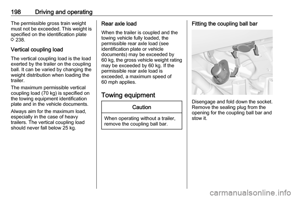
Disengage and fold down the socket. Remove the sealing plug from the
opening for the coupling ball bar and
stow it.
Page 202 of 263
200Driving and operatingInsert the tensioned coupling ball bar
in the opening and push firmly
upwards until it audibly engages.
The rotary handle snaps back into its
original position resting against the
coupling ball bar without a gap.9 Warning
Do not touch rotary handle during
insertion.
Lock the coupling ball bar by turning
the key to position e. Remove the key
and close the protective flap.
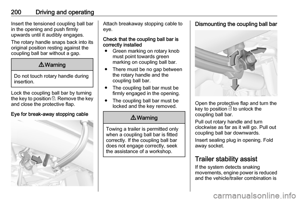
Eye for break-away stopping cable
Attach breakaway stopping cable to
eye.
Check that the coupling ball bar is correctly installed
● Green marking on rotary knob must point towards green
marking on coupling ball bar.
● There must be no gap between the rotary handle and the
coupling ball bar.
● The coupling ball bar must be firmly engaged in the opening.
● The coupling ball bar must be locked and the key removed.9Warning
Towing a trailer is permitted only
when a coupling ball bar is fitted correctly. If the coupling ball bardoes not engage correctly, seekthe assistance of a workshop.
Dismounting the coupling ball bar
Open the protective flap and turn the
key to position c to unlock the
coupling ball bar.
Pull out rotary handle and turn
clockwise as far as it will go. Pull out coupling ball bar downwards.
Insert sealing plug in opening. Fold away socket.
Trailer stability assist
If the system detects snaking
movements, engine power is reduced
and the vehicle/trailer combination is
Page 204 of 263

202Vehicle careVehicle careGeneral Information...................202
Accessories and vehicle modifications .......................... 202
Vehicle storage ........................203
End-of-life vehicle recovery .....204
Vehicle checks ........................... 204
Performing work ......................204
Bonnet ..................................... 204
Engine oil ................................. 205
Engine coolant ......................... 206
Washer fluid ............................ 207
Brakes ..................................... 207
Brake fluid ............................... 207
Vehicle battery ......................... 207
Diesel fuel system bleeding .....209
Wiper blade replacement ........209
Bulb replacement .......................210
Halogen headlights ..................210
LED headlights ........................ 211
Fog lights ................................. 211
Tail lights ................................. 212
Side turn signal lights ..............215
Number plate light ...................215
Interior lights ............................ 215
Instrument panel illumination ...215Vehicle tools .............................. 216
Tools ........................................ 216
Wheels and tyres .......................217
Winter tyres ............................. 217
Tyre designations ....................217
Tyre pressure .......................... 217
Tyre deflation detection system .................................... 218
Tread depth ............................. 219
Changing tyre and wheel size . 220
Wheel covers ........................... 220
Tyre chains .............................. 221
Tyre repair kit .......................... 221
Wheel changing .......................224
Spare wheel ............................ 227
Jump starting ............................. 228
Towing ....................................... 229
Towing the vehicle ...................229
Towing another vehicle ...........230
Appearance care .......................231
Exterior care ............................ 231
Interior care ............................. 233General Information
Accessories and vehicle modifications
We recommend the use of genuine
parts and accessories and factory
approved parts specific for your
vehicle type. We cannot assess or guarantee reliability of other products - even if they have a regulatory or
otherwise granted approval.
Any modification, conversion or other
changes made to standard vehicle
specifications (including, without
limitation, software modifications,
modifications of the electronic control units) may invalidate the warranty
offered by Vauxhall. Furthermore,
such changes may affect driver
assistance systems, may impact fuel
consumption, CO 2 emissions and
other emissions of the vehicle and
cause the vehicle to no longer
conform to the operating permit,
impacting the validity of your vehicle
registration.
Page 218 of 263
216Vehicle careVehicle tools
Tools
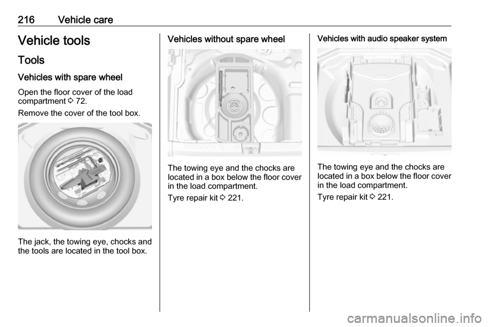
Vehicles with spare wheel Open the floor cover of the load
compartment 3 72.
Remove the cover of the tool box.
The jack, the towing eye, chocks and
the tools are located in the tool box.
Vehicles without spare wheel
The towing eye and the chocks are
located in a box below the floor cover in the load compartment.
Tyre repair kit 3 221.
Vehicles with audio speaker system
The towing eye and the chocks are
located in a box below the floor cover in the load compartment.
Tyre repair kit 3 221.
Page 229 of 263
Vehicle care227Front arm position of the lifting
platform centrically under the relevant
vehicle jacking point.
Spare wheel
Some vehicles are equipped with a
tyre repair kit instead of a temporary
spare wheel. 3 221
Temporary spare wheelCaution
The use of the temporary spare
wheel could affect driveability.
Have the defective tyre renewed
or repaired as soon as possible.
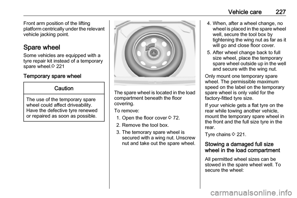
The spare wheel is located in the load
compartment beneath the floor
covering.
To remove: 1. Open the floor cover 3 72.
2. Remove the tool box.
3. The temorary spare wheel is secured with a wing nut. Unscrew
nut and take out the spare wheel.
4. When, after a wheel change, no wheel is placed in the spare wheelwell, secure the tool box by
tightening the wing nut as far as it will go and close floor cover.
5. After wheel change back to full size wheel, place the temporary
spare wheel outside up in the well
and secure with the wing nut.
Only mount one temporary spare
wheel. The permissible maximum
speed on the label on the temporary
spare wheel is only valid for the
factory-fitted tyre size.
If your vehicle gets a flat tyre on the rear while towing another vehicle,
mount the temporary spare wheel in
the front and the full size tyre in the
rear.
Tyre chains 3 221.
Stowing a damaged full size
wheel in the load compartment
All permitted wheel sizes can be
stowed in the spare wheel well. To
secure the wheel:
Page 231 of 263
Vehicle care229● The vehicles must not come intocontact with each other during
the jump starting process.
● Apply the parking brake, transmission in neutral,
automatic transmission in P.
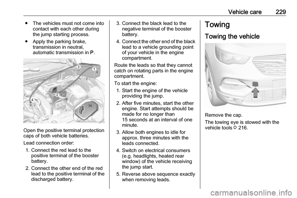
Open the positive terminal protection
caps of both vehicle batteries.
Lead connection order: 1. Connect the red lead to the positive terminal of the booster
battery.
2. Connect the other end of the red lead to the positive terminal of the
discharged battery.
3. Connect the black lead to the negative terminal of the boosterbattery.
4. Connect the other end of the black
lead to a vehicle grounding point
of your vehicle in the engine
compartment.
Route the leads so that they cannot
catch on rotating parts in the engine
compartment.
To start the engine: 1. Start the engine of the vehicle providing the jump.
2. After five minutes, start the other engine. Start attempts should be
made for no longer than
15 seconds at an interval of one
minute.
3. Allow both engines to idle for approx. three minutes with the
leads connected.
4. Switch on electrical consumers (e.g. headlights, heated rear
window) of the vehicle receiving
the jump start.
5. Reverse above sequence exactly when removing leads.Towing
Towing the vehicle
Remove the cap.
The towing eye is stowed with the
vehicle tools 3 216.
Page 232 of 263
230Vehicle care
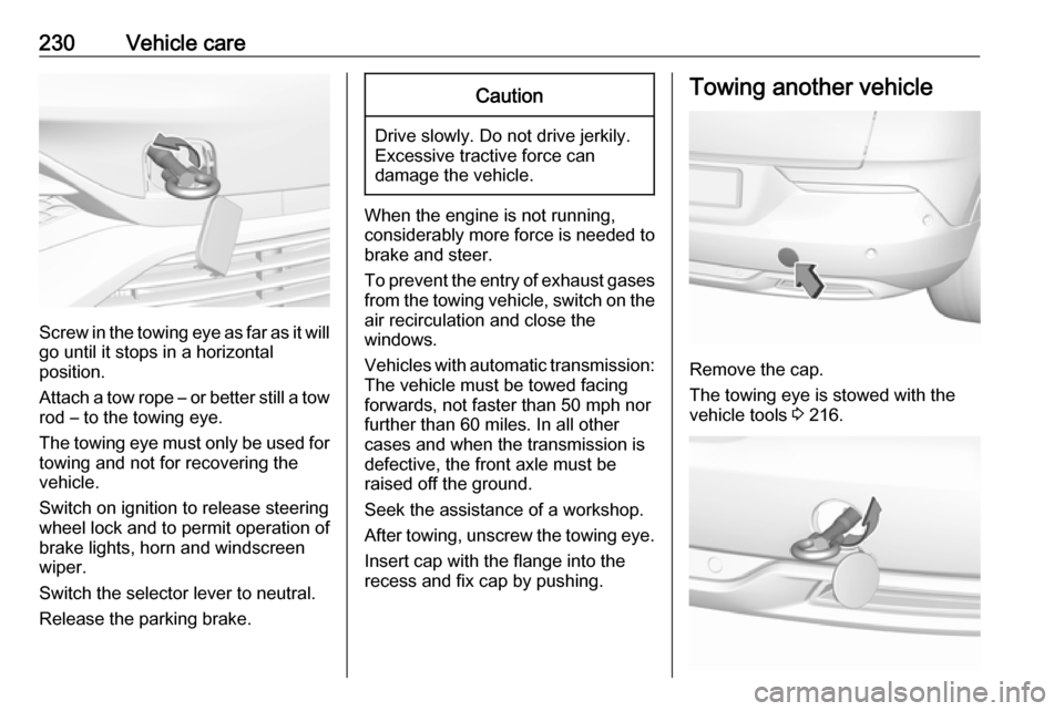
Screw in the towing eye as far as it will
go until it stops in a horizontal
position.
Attach a tow rope – or better still a tow
rod – to the towing eye.
The towing eye must only be used for towing and not for recovering the
vehicle.
Switch on ignition to release steering
wheel lock and to permit operation of
brake lights, horn and windscreen
wiper.
Switch the selector lever to neutral.
Release the parking brake.
Caution
Drive slowly. Do not drive jerkily.
Excessive tractive force can
damage the vehicle.
When the engine is not running,
considerably more force is needed to
brake and steer.
To prevent the entry of exhaust gases from the towing vehicle, switch on the
air recirculation and close the
windows.
Vehicles with automatic transmission: The vehicle must be towed facing
forwards, not faster than 50 mph nor further than 60 miles. In all other
cases and when the transmission is
defective, the front axle must be
raised off the ground.
Seek the assistance of a workshop. After towing, unscrew the towing eye.
Insert cap with the flange into the
recess and fix cap by pushing.
Towing another vehicle
Remove the cap.
The towing eye is stowed with the
vehicle tools 3 216.
Page 233 of 263
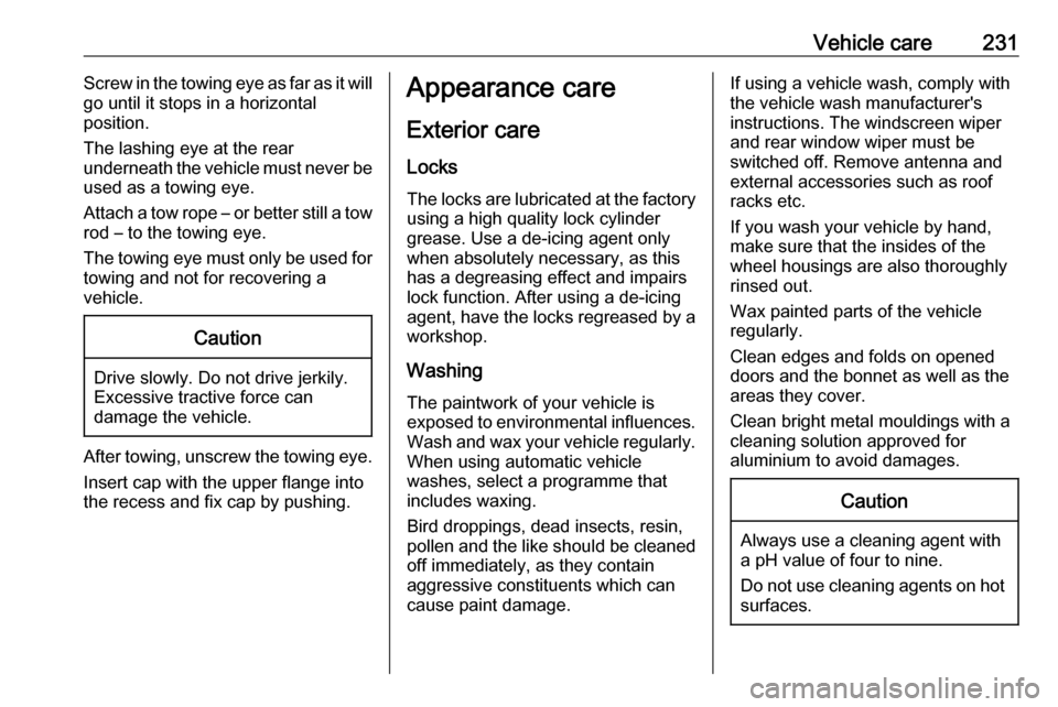
Vehicle care231Screw in the towing eye as far as it will
go until it stops in a horizontal
position.
The lashing eye at the rear
underneath the vehicle must never be used as a towing eye.
Attach a tow rope – or better still a tow
rod – to the towing eye.
The towing eye must only be used for
towing and not for recovering a
vehicle.Caution
Drive slowly. Do not drive jerkily.
Excessive tractive force can
damage the vehicle.
After towing, unscrew the towing eye.
Insert cap with the upper flange into
the recess and fix cap by pushing.
Appearance care
Exterior care LocksThe locks are lubricated at the factoryusing a high quality lock cylinder
grease. Use a de-icing agent only
when absolutely necessary, as this
has a degreasing effect and impairs
lock function. After using a de-icing
agent, have the locks regreased by a
workshop.
WashingThe paintwork of your vehicle is
exposed to environmental influences.
Wash and wax your vehicle regularly.
When using automatic vehicle
washes, select a programme that
includes waxing.
Bird droppings, dead insects, resin,
pollen and the like should be cleaned
off immediately, as they contain
aggressive constituents which can
cause paint damage.If using a vehicle wash, comply with
the vehicle wash manufacturer's instructions. The windscreen wiperand rear window wiper must be
switched off. Remove antenna and
external accessories such as roof
racks etc.
If you wash your vehicle by hand,
make sure that the insides of the
wheel housings are also thoroughly
rinsed out.
Wax painted parts of the vehicle regularly.
Clean edges and folds on opened
doors and the bonnet as well as the
areas they cover.
Clean bright metal mouldings with a
cleaning solution approved for
aluminium to avoid damages.Caution
Always use a cleaning agent with
a pH value of four to nine.
Do not use cleaning agents on hot surfaces.
Page 235 of 263
Vehicle care233After the underbody is washed, check
the underbody and have it waxed if
necessary.
Bitumen/rubber materials could
damage the PVC coating. Have
underbody work carried out by a
workshop.
Before and after winter, wash the
underbody and have the protective
wax coating checked.
Liquid gas system9 Danger
Liquid gas is heavier than air and
can collect in sink points.
Take care when performing work
at the underbody in a pit.
For painting work and when using a
drying booth at a temperature above
60 °C, the liquid gas tank must be
removed.
Do not make any modifications to the
liquid gas system.
Towing equipment
Do not clean the coupling ball bar with a steam-jet or high-pressure jet
cleaner.
Interior care
Interior and upholstery
Only clean the vehicle interior,
including the instrument panel fascia
and panelling, with a dry cloth or
interior cleaner.
Clean the leather upholstery with
clear water and a soft cloth. In case of heavy soiling, use leather care.
The instrument cluster and the
displays should only be cleaned using
a soft damp cloth. If necessary use a
weak soap solution.
Clean fabric upholstery with a
vacuum cleaner and brush. Remove
stains with an upholstery cleaner.
Clothing fabrics may not be
colourfast. This could cause visible
discolourations, especially on light-coloured upholstery. Removable
stains and discolourations should be
cleaned as soon as possible.
Clean seat belts with lukewarm water or interior cleaner.Caution
Close Velcro fasteners as open
Velcro fasteners on clothing could
damage seat upholstery.
The same applies to clothing with
sharp-edged objects, like zips or
belts or studded jeans.
Plastic and rubber parts
Plastic and rubber parts can be
cleaned with the same cleaner as
used to clean the body. Use interior cleaner if necessary. Do not use any
other agent. Avoid solvents and petrol in particular. Do not use high-
pressure jet cleaners.