service VAUXHALL MERIVA 2015 Owner's Manual
[x] Cancel search | Manufacturer: VAUXHALL, Model Year: 2015, Model line: MERIVA, Model: VAUXHALL MERIVA 2015Pages: 245, PDF Size: 7.76 MB
Page 3 of 245

Introduction.................................... 2
In brief ............................................ 6
Keys, doors and windows ............19
Seats, restraints ........................... 34
Storage ........................................ 61
Instruments and controls .............81
Lighting ...................................... 115
Climate control ........................... 124
Driving and operating .................134
Vehicle care ............................... 167
Service and maintenance ..........216
Technical data ........................... 219
Customer information ................235
Index .......................................... 238Contents
Page 5 of 245

Introduction3Vehicle specific data
Please enter your vehicle's data on
the previous page to keep it easily
accessible. This information is
available in the sections "Service and maintenance" and "Technical data"
as well as on the identification plate.
Introduction
Your vehicle is a designed
combination of advanced technology, safety, environmental friendliness
and economy.
This Owner's Manual provides you
with all the necessary information to
enable you to drive your vehicle
safely and efficiently.
Make sure your passengers are
aware of the possible risk of accident
and injury which may result from
improper use of the vehicle.
You must always comply with the
specific laws and regulations of the
country that you are in. These laws
may differ from the information in this Owner's Manual.When this Owner's Manual refers to aworkshop visit, we recommend your
Vauxhall Authorised Repairer. For
gas vehicles, we recommend a
Vauxhall Authorised Repairer
licensed to service gas vehicles.
All Vauxhall Authorised Repairers
provide first-class service at
reasonable prices. Experienced
mechanics trained by Vauxhall work
according to specific Vauxhall
instructions.
The customer literature pack should
always be kept ready to hand in the
vehicle.
Using this manual ■ This manual describes all options and features available for this
model. Certain descriptions,
including those for display and
menu functions, may not apply to
your vehicle due to model variant,
country specifications, special
equipment or accessories.
■ The "In brief" section will give you an initial overview.■ The table of contents at thebeginning of this manual and withineach section shows where the
information is located.
■ The index will enable you to search
for specific information.
■ This Owner's Manual depicts left- hand drive vehicles. Operation is
similar for right-hand drive vehicles.
■ The Owner's Manual uses the factory engine designations. The
corresponding sales designations
can be found in the section
"Technical data".
■ Directional data, e.g. left or right, or
front or back, always relate to the
direction of travel.
■ The vehicle display screens may not support your specific language.
■ Display messages and interior labelling are written in bold letters.
Page 92 of 245

90Instruments and controls
Because of the fuel remaining in the
tank, the top-up quantity may be less
than the specified tank capacity.
Fuel selector
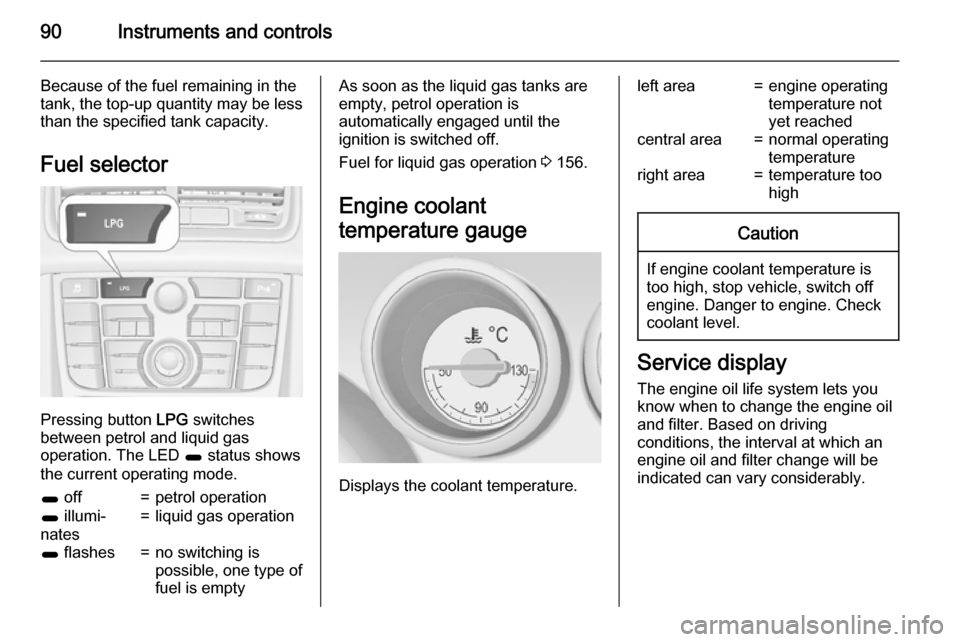
Pressing button LPG switches
between petrol and liquid gas
operation. The LED 1 status shows
the current operating mode.
1 off=petrol operation1 illumi‐
nates=liquid gas operation1 flashes=no switching is
possible, one type of
fuel is emptyAs soon as the liquid gas tanks are
empty, petrol operation is
automatically engaged until the
ignition is switched off.
Fuel for liquid gas operation 3 156.
Engine coolant
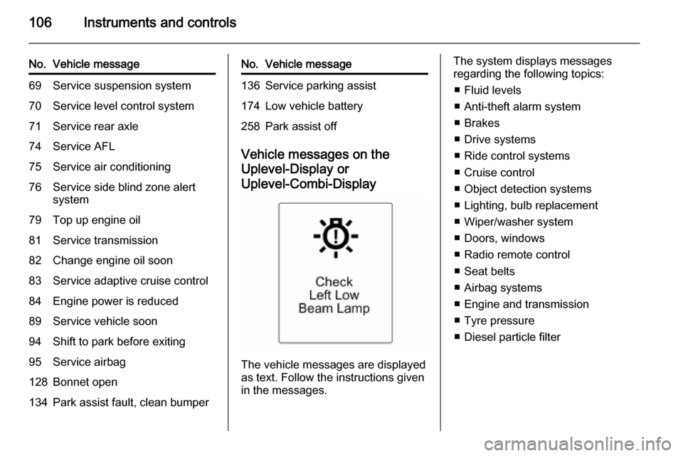
temperature gauge
Displays the coolant temperature.
left area=engine operating
temperature not
yet reachedcentral area=normal operating
temperatureright area=temperature too
highCaution
If engine coolant temperature is
too high, stop vehicle, switch off
engine. Danger to engine. Check
coolant level.
Service display
The engine oil life system lets you
know when to change the engine oil
and filter. Based on driving
conditions, the interval at which an
engine oil and filter change will be
indicated can vary considerably.
Page 93 of 245

Instruments and controls91
In the Uplevel-Display or
Uplevel-Combi-Display the remaining
oil life duration is displayed in the
Vehicle Information Menu .
In the Midlevel-Display the remaining
engine oil life duration is displayed by
the control indicator I. The ignition
must be switched on, with the engine not running.
The menu and function can be
selected via the buttons on the turn
signal lever.
To display the remaining engine oil life duration:Press the MENU button to select the
Vehicle Information Menu .
Turn the adjuster wheel to select
Remaining Oil Life .
The system must be reset every time
the engine oil is changed to allow
proper functionality. Seek the
assistance of a workshop.
Press the SET/CLR button to reset.
The ignition must be switched on, with the engine not running.
When the system has calculated that
engine oil life has been diminished,
Change Engine Oil Soon or a warning
code appears in the Driver
Information Centre. Have engine oil
and filter changed by a workshop
within one week or 300 miles
(whichever occurs first).
Driver Information Centre 3 99.
Service information 3 216.
Control indicators
The control indicators described are
not present in all vehicles. The
description applies to all instrument
versions.
Depending on the equipment the
position of the control indicators may vary.
When the ignition is switched on,
most control indicators will illuminate
briefly as a functionality test.
The control indicator colours mean:red=danger, important reminderyellow=warning, information, faultgreen=confirmation of activationblue=confirmation of activationwhite=confirmation of activation
Page 96 of 245

94Instruments and controls9Warning
Have the cause of the fault
remedied immediately by a
workshop.
Belt pretensioners, airbag system
3 44, 3 48.
Airbag deactivation
V illuminates yellow.
Illuminates for approx. 60 seconds
after the ignition is switched on. The
front passenger airbag is activated.
* illuminates yellow.
The front passenger airbag is
deactivated 3 53.
9 Danger
Risk of fatal injury for a child using
a child restraint system together
with activated front passenger
airbag.
Risk of fatal injury for an adult
person with deactivated front
passenger airbag.
Charging system
p illuminates red.
Illuminates when the ignition is
switched on and extinguishes shortly
after the engine starts.
Illuminates when the engine is
running
Stop, switch off engine. Vehicle
battery is not charging. Engine
cooling may be interrupted. The
brake servo unit may cease to be
effective. Seek the assistance of a
workshop.
Malfunction indicator light
Z illuminates or flashes yellow.
Illuminates when the ignition is
switched on and extinguishes shortly
after the engine starts.
Illuminates when the engine is
running
Fault in the emission control system. The permitted emission limits may be
exceeded. Seek the assistance of a
workshop immediately.
Flashes when the engine isrunning
Fault that could lead to catalytic
converter damage. Ease up on the
accelerator until the flashing stops.
Seek the assistance of a workshop
immediately.
Service vehicle soon g illuminates yellow.
Additionally a warning message or a
warning code is displayed.
The vehicle needs a service.
Seek the assistance of a workshop.
Vehicle messages 3 104.
Page 97 of 245

Instruments and controls95Brake and clutch system
Brake and clutch fluid level R illuminates red.
The brake and clutch fluid level is too low 3 172.9 Warning
Stop. Do not continue your
journey. Consult a workshop.
Operate pedal
- illuminates or flashes yellow.
Illuminates
Brake pedal needs to be depressed
to release the electric parking brake
3 146.
Clutch pedal needs to be depressed
to start the engine in Autostop mode.
Stop-start system 3 137.
Flashes
Clutch pedal needs to be depressed
for a main start of the engine 3 16,
3 135.
Electric parking brake
m illuminates or flashes red.
Illuminates Electrical parking brake is applied3 146.
Flashes
Electrical parking brake is not fully applied or released. Switch on
ignition, depress brake pedal and attempt to reset the system by first
releasing and then applying the
electrical parking brake. If m remains
flashing, do not drive and seek the
assistance of a workshop.
Electric parking brake fault j illuminates or flashes yellow.
Illuminates
Electrical parking brake is operating
with degraded performance 3 146.Flashes
Electrical parking brake is in service
mode. Stop vehicle, apply and
release the electrical parking brake to
reset.9 Warning
Have the cause of the fault
remedied immediately by a
workshop.
Antilock brake system
(ABS) u illuminates yellow.
Illuminates for a few seconds after the ignition is switched on. The system is
ready for operation when the control
indicator extinguishes.
If the control indicator does not go out after a few seconds, or if it illuminates while driving, there is a fault in the
ABS. The brake system remains
operational but without ABS
regulation.
Antilock brake system 3 145.
Page 107 of 245

Instruments and controls105
No.Vehicle message6Depress brake pedal to release
electrical parking brake7Turn steering wheel, switch
ignition off and then on9Turn steering wheel, start
engine again12Vehicle overloaded13Compressor overheated15Centre high-mounted brake
light failure16Brake light failure17Headlight levelling malfunction18Left low beam failure19Rear fog light failure20Right low beam failure21Left sidelight failure22Right sidelight failure23Reversing light failureNo.Vehicle message24Number plate light failure25Left front turn signal failure26Left rear turn signal failure27Right front turn signal failure28Right rear turn signal failure29Check trailer brake light30Check trailer reversing light31Check left trailer turn signal32Check right trailer turn signal33Check trailer rear fog light34Check trailer rear light35Replace battery in radio remote
control48Clean side blind zone alert
system53Tighten gas cap54Water in diesel fuel filterNo.Vehicle message55Diesel particle filter is full
3 14056Tyre pressure imbalance on
front axle57Tyre pressure imbalance on
rear axle58Tyres without TPMS sensors
detected59Open and then close driver
window60Open and then close front
passenger window61Open and then close rear left
window62Open and then close rear right
window65Theft attempted66Service theft alarm system67Service steering wheel lock68Service power steering
Page 108 of 245

106Instruments and controls
No.Vehicle message69Service suspension system70Service level control system71Service rear axle74Service AFL75Service air conditioning76Service side blind zone alert
system79Top up engine oil81Service transmission82Change engine oil soon83Service adaptive cruise control84Engine power is reduced89Service vehicle soon94Shift to park before exiting95Service airbag128Bonnet open134Park assist fault, clean bumperNo.Vehicle message136Service parking assist174Low vehicle battery258Park assist off
Vehicle messages on the
Uplevel-Display or Uplevel-Combi-Display
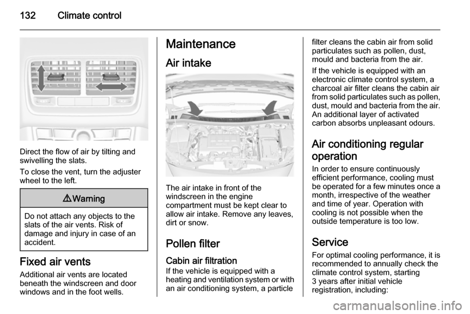
The vehicle messages are displayed
as text. Follow the instructions given
in the messages.
The system displays messages
regarding the following topics:
■ Fluid levels
■ Anti-theft alarm system
■ Brakes
■ Drive systems
■ Ride control systems
■ Cruise control
■ Object detection systems
■ Lighting, bulb replacement
■ Wiper/washer system
■ Doors, windows
■ Radio remote control
■ Seat belts
■ Airbag systems
■ Engine and transmission
■ Tyre pressure
■ Diesel particle filter
Page 134 of 245

132Climate control
Direct the flow of air by tilting and
swivelling the slats.
To close the vent, turn the adjuster
wheel to the left.
9 Warning
Do not attach any objects to the
slats of the air vents. Risk of
damage and injury in case of an
accident.
Fixed air vents
Additional air vents are located
beneath the windscreen and door windows and in the foot wells.
Maintenance
Air intake
The air intake in front of the
windscreen in the engine
compartment must be kept clear to
allow air intake. Remove any leaves,
dirt or snow.
Pollen filterCabin air filtration
If the vehicle is equipped with a
heating and ventilation system or with an air conditioning system, a particle
filter cleans the cabin air from solidparticulates such as pollen, dust,
mould and bacteria from the air.
If the vehicle is equipped with an
electronic climate control system, a
charcoal air filter cleans the cabin air
from solid particulates such as pollen, dust, mould and bacteria from the air.
An additional layer of activated
carbon absorbs unpleasant odours.
Air conditioning regular
operation In order to ensure continuously
efficient performance, cooling must
be operated for a few minutes once a
month, irrespective of the weather
and time of year. Operation with
cooling is not possible when the
outside temperature is too low.
Service
For optimal cooling performance, it is recommended to annually check the
climate control system, starting
3 years after initial vehicle
registration, including:
Page 138 of 245

136Driving and operating
Diesel engine: turn the key to position2 for preheating until control
indicator ! extinguishes.
Turn the key briefly to position 3 and
release: an automatic procedure operates the starter with a short delay
as long as the engine is running, see
Automatic Starter Control.
Before restarting or to switch off the
engine, turn the key back to position
0 .
During an Autostop, the engine can
be started by depressing the clutch
pedal.Starting the vehicle at low
temperatures
The start of the engine without
additional heaters is possible down to -25 °С for diesel engines and -30 °C
for petrol engines. Required is an engine oil with the correct viscosity,
the correct fuel, performed services
and a sufficiently charged vehicle
battery. With temperatures below
-30 °C the automatic transmission
needs a warming phase of approx. 5
minutes. The selector lever must be
in position P.
Automatic Starter Control
This function controls the engine
starting procedure. The driver does
not have to hold the key in position 3.
Once applied, the system will go on starting automatically until the engine
is running. Because of the checking
procedure, the engine starts running
after a short delay.Possible reasons for a non-starting
engine:
■ Clutch pedal not operated (manual transmission)
■ Brake pedal not operated or selector lever not in P or N
(automatic transmission)
■ Timeout occurred
Turbo engine warm-up
Upon start-up, engine available
torque may be limited for a short time, especially when the engine
temperature is cold. The limitation is
to allow the lubrication system to fully
protect the engine.
Overrun cut-off The fuel supply is automatically cut off
during overrun, i.e. when the vehicle
is driven with a gear engaged but
accelerator is released.