tyre pressure VAUXHALL MOKKA 2014.5 Owner's Manual
[x] Cancel search | Manufacturer: VAUXHALL, Model Year: 2014.5, Model line: MOKKA, Model: VAUXHALL MOKKA 2014.5Pages: 219, PDF Size: 6 MB
Page 18 of 219
16In briefTransmission
Manual transmission
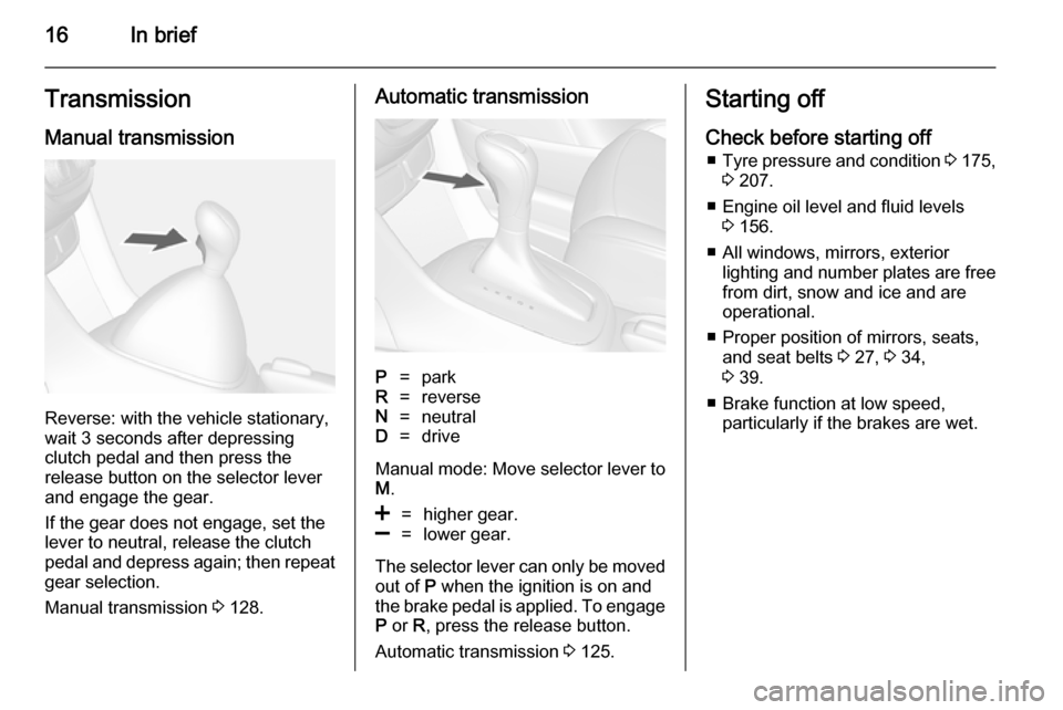
Reverse: with the vehicle stationary,
wait 3 seconds after depressing
clutch pedal and then press the
release button on the selector lever
and engage the gear.
If the gear does not engage, set the
lever to neutral, release the clutch
pedal and depress again; then repeat
gear selection.
Manual transmission 3 128.
Automatic transmissionP=parkR=reverseN=neutralD=drive
Manual mode: Move selector lever to
M .
<=higher gear.]=lower gear.
The selector lever can only be moved
out of P when the ignition is on and
the brake pedal is applied. To engage P or R, press the release button.
Automatic transmission 3 125.
Starting off
Check before starting off ■ Tyre pressure and condition 3 175,
3 207.
■ Engine oil level and fluid levels 3 156.
■ All windows, mirrors, exterior lighting and number plates are free
from dirt, snow and ice and are
operational.
■ Proper position of mirrors, seats, and seat belts 3 27, 3 34,
3 39.
■ Brake function at low speed, particularly if the brakes are wet.
Page 73 of 219

Storage71
luggage (7 kg) and all fluids (tank90 % full).
Optional equipment and
accessories increase the kerb
weight.
■ Driving with a roof load increases the sensitivity of the vehicle to
cross-winds and has a detrimental
effect on vehicle handling due to
the vehicle's higher centre of
gravity. Distribute the load evenly
and secure it properly with retaining
straps. Adjust the tyre pressure and vehicle speed according to the load
conditions. Check and retighten the straps frequently.
Do not drive faster than 75 mph.
■ The permissible roof load is 75 kg. The roof load is the combined
weight of the roof rack and the load.
Page 89 of 219

Instruments and controls87Electronic Stability Control
off n illuminates yellow.
The system is deactivated.
Electronic Stability Control
and Traction Control
system b illuminates or flashes yellow.
Illuminates A fault in the system is present.
Continued driving is possible. Driving
stability, however, may deteriorate
depending on road surface
conditions.
Have the cause of the fault remedied
by a workshop.
Flashes The system is actively engaged.
Engine output may be reduced and
the vehicle may be braked
automatically to a small degree.
Electronic Stability Control 3 131,
Traction Control system 3 131.Traction Control system off
k illuminates yellow.
The system is deactivated.
Preheating
! illuminates yellow.
Preheating is activated. Only
activates when outside temperature
is low.
Diesel particle filter
% illuminates or flashes yellow.
The diesel particle filter requires
cleaning.
Continue driving until %
extinguishes. If possible, do not allow engine speed to drop below
2000 rpm.
Illuminates
The diesel particle filter is full. Start
cleaning process as soon as
possible.Flashes
The maximum filling level of the filter
is reached. Start cleaning process
immediately to avoid damage to the
engine.
Diesel particle filter 3 123, Stop-start
system 3 120.
Tyre pressure monitoring
system
w illuminates or flashes yellow.
Illuminates
Tyre pressure loss. Stop immediately
and check tyre pressure.
Flashes Fault in system or tyre without
pressure sensor mounted (e.g. spare wheel). After 60-90 seconds the
control indicator illuminates
continuously. Consult a workshop.
Tyre pressure monitor system
3 175.
Page 93 of 219

Instruments and controls91
Vehicle Information MenuPress the MENU button to select the
Vehicle Information Menu , or on
Uplevel-Combi-Display select X.
Turn the adjuster wheel to select a
submenu. Press the SET/CLR button
to confirm.
Follow the instructions given in the
submenus.
Possible submenus can be,
depending on the version:
■ Unit : displayed units can be
changed
■ Tyre Pressure : checks tyre
pressure of all wheels during
driving 3 175
■ Remaining Oil Life : indicates when
to change the engine oil and filter
3 81
■ Traffic Sign Assistant : displays
detected traffic signs for the current route section 3 141
■ Speed Warning : if exceeding the
preset speed, a warning chime will
be activatedSelection and indication can be
different between Midlevel- and
Uplevel-Combi-Display.
Trip/Fuel Information Menu
Press the MENU button to select the
Trip/Fuel Information Menu , or select
W on Uplevel-Combi-Display.
Turn the adjuster wheel to select a
submenu. Press the SET/CLR button
to confirm.
■ Trip odometer 1
■ Trip odometer 2
■ Digital speed
Trip odometer 2 and digital speed are
only available on vehicles with
Uplevel-Combi-Display.
On vehicles with trip computer more
submenus are available.
Selection and indication can be
different between Midlevel- and
Uplevel-Combi-Display.
Trip/Fuel Information Menu, Trip
Computer 3 96.ECO Information Menu
Press the MENU button to select
s in the top line of the Uplevel-
Combi-Display.
Turn the adjuster wheel to select a
submenu. Press the SET/CLR button
to confirm.
Submenus are:
■ Shift indication : Current gear is
indicated inside an arrow. The
graphic above recommends
upshifting for fuel saving reasons.
Eco index display : The current fuel
consumption is indicated on a segment display. For economical
Page 97 of 219
Instruments and controls95
No.Vehicle message28Right rear turn signal failure53Tighten gas cap54Water in diesel fuel filterS68Service power steeringS73Service all-wheel drive systemS75Service air conditioningS79Top up engine oilS81Service transmissionS82Change engine oil soonS84Engine power is reducedS89Service vehicle soon128Bonnet open134Park assist fault, clean
bumperS136Service parking assist174Low batteryNotice
"S" means "Service vehicle soon".
Seek the assistance of a workshop
immediately.
Vehicle messages on the
Uplevel-Combi-Display
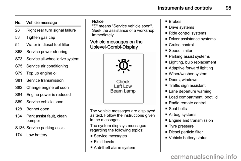
The vehicle messages are displayed
as text. Follow the instructions given
in the messages.
The system displays messages
regarding the following topics:
■ Service messages
■ Fluid levels
■ Anti-theft alarm system
■ Brakes
■ Drive systems
■ Ride control systems
■ Driver assistance systems
■ Cruise control
■ Speed limiter
■ Parking assist systems
■ Lighting, bulb replacement
■ Adaptive forward lighting
■ Wiper/washer system
■ Doors, windows
■ Traffic sign assistant
■ Lane departure warning
■ Load compartment, boot lid
■ Radio remote control
■ Seat belts
■ Airbag systems
■ Engine and transmission
■ Tyre pressure
■ Diesel particle filter
■ Vehicle battery status
Page 154 of 219

152Driving and operatingTrailer hitch
General information
Only use towing equipment that has
been approved for your vehicle.
Entrust retrofitting of towing
equipment to a workshop. It may be
necessary to make changes that
affect the cooling system, heat
shields or other equipment.
Fitting of towing equipment could
cover the opening of the towing eye.
If this is the case, use the coupling ball
bar for towing. Always keep the
coupling ball bar in the vehicle.
Driving characteristics and
towing tips Before attaching a trailer, lubricate
the coupling ball. However, do not do
so if a stabiliser, which acts on the coupling ball, is being used to reduce
snaking movements.
For trailers with low driving stability
and caravan trailers with a permitted
gross vehicle weight of more than1000 kg a speed of 50 mph must not
be exceeded; the use of a stabiliser is recommended.
If the trailer starts snaking, drive more
slowly, do not attempt to correct the
steering and brake sharply if
necessary.
When driving downhill, drive in the
same gear as if driving uphill and
drive at a similar speed.
Adjust tyre pressure to the value
specified for full load 3 207.
Trailer towing Trailer loads
The permissible trailer loads are
vehicle and engine-dependent
maximum values which must not be exceeded. The actual trailer load is
the difference between the actual
gross weight of the trailer and the
actual coupling socket load with the
trailer coupled.
The permissible trailer loads are
specified in the vehicle documents. In general, they are valid for gradients
up to max. 12 %.The permitted trailer loads apply up to
the specified incline and up to an
altitude of 1000 metres above sea
level. Since engine power decreases
as altitude increases due to the air becoming thinner, therefore reducing
climbing ability, the permissible gross train weight also decreases by 10 %
for every 1000 metres of additional
altitude. The gross train weight does
not have to be reduced when driving
on roads with slight inclines (less than
8 %, e.g. motorways).
The permissible gross train weight
must not be exceeded. This weight is
specified on the identification plate
3 197.
Vertical coupling load
The vertical coupling load is the load
exerted by the trailer on the coupling
ball. It can be varied by changing the
weight distribution when loading the
trailer.
The maximum permissible vertical
coupling load (75 kg) is specified on
the towing equipment identification
plate and in the vehicle documents.
Always aim for the maximum load,
Page 156 of 219

154Vehicle careVehicle careGeneral Information...................154
Vehicle checks ........................... 155
Bulb replacement .......................162
Electrical system ........................168
Vehicle tools .............................. 173
Wheels and tyres .......................174
Jump starting ............................. 187
Towing ....................................... 189
Appearance care .......................191General Information
Accessories and vehicle
modifications
We recommend the use of genuine parts and accessories and factory
approved parts specific for your
vehicle type. We cannot assess or
guarantee reliability of other products
- even if they have a regulatory or
otherwise granted approval.
Do not make any modifications to the electrical system, e.g. changes of
electronic control units (chip tuning).Caution
When transporting the vehicle on
a train or on a recovery vehicle, the
mud flaps might be damaged.
Vehicle storage
Storage for a long period of time
If the vehicle is to be stored for several months:
■ Wash and wax the vehicle.
■ Have the wax in the engine compartment and underbody
checked.
■ Clean and preserve the rubber seals.
■ Fill up fuel tank completely.
■ Change the engine oil.
■ Drain the washer fluid reservoir.
■ Check the coolant antifreeze and corrosion protection.
■ Adjust tyre pressure to the value specified for full load.
■ Park the vehicle in a dry, well ventilated place. Engage first orreverse gear or set selector lever to P . Prevent the vehicle from rolling.
■ Do not apply the parking brake.
Page 157 of 219

Vehicle care155
■ Open the bonnet, close all doorsand lock the vehicle.
■ Disconnect the clamp from the negative terminal of the vehicle
battery. Beware that all systems are
not functional, e.g. anti-theft alarm
system.
Putting back into operation
When the vehicle is to be put back into
operation:
■ Connect the clamp to the negative terminal of the vehicle battery.
Activate the electronics of the
power windows.
■ Check tyre pressure.
■ Fill up the washer fluid reservoir.
■ Check the engine oil level.
■ Check the coolant level.
■ Fit the number plate if necessary.
End-of-life vehicle
recovery
Information on end-of-life vehicle
recovery centres and the recycling of
end-of-life vehicles is available on ourwebsite, where legally required. Only
entrust this work to an authorised
recycling centre.
Gas vehicles must be recycled by a
service centre authorised for gas
vehicles.Vehicle checks
Performing work9 Warning
Only perform engine compartment
checks when the ignition is off.
The cooling fan may start
operating even if the ignition is off.
Page 177 of 219

Vehicle care175Tyre pressure
Check the pressure of cold tyres at
least every 14 days and before any
long journey. Do not forget the spare
wheel. This also applies to vehicles
with tyre pressure monitoring system.
Unscrew the valve cap.
Tyre pressure 3 207 and on the label
on the driver's door frame.
The tyre pressure data refers to cold
tyres. It applies to summer and winter tyres.
Always inflate the spare tyre to the
pressure specified for full load.
The ECO tyre pressure serves to
achieve the smallest amount of fuel
consumption possible.
Incorrect tyre pressures will impair
safety, vehicle handling, comfort and
fuel economy and will increase tyre
wear.
Tyre pressures differ depending on
various options. For the correct tyre
pressure value, follow the procedure
below:
1. Identify the engine identifier code.
Engine data 3 202.
2. Identify the respective tyre.
The tyre pressure tables show all
possible tyre combinations 3 207.
For the tyres approved for your
vehicle, refer to the EEC Certificate of Conformity provided with your vehicle
or other national registration
documents.
The driver is responsible for correct
adjustment of tyre pressure.9 Warning
If the pressure is too low, this can
result in considerable tyre warm-
up and internal damage, leading to tread separation and even to tyre
blow-out at high speeds.
Tyre pressure monitoring
system
The Tyre Pressure Monitoring
System (TPMS) uses radio and
sensor technology to check tyre
pressure levels.
All wheels must be equipped with
pressure sensors and the tyres must
have the prescribed pressure.
Notice
In countries where the tyre pressure
monitoring system is legally
required, the use of wheels without
pressure sensors will invalidate the
vehicle type approval.
Page 178 of 219

176Vehicle care
The TPMS sensors monitor the air
pressure in the tyres and transmit tyre pressure readings to a receiver
located in the vehicle.
Each tyre, including the spare, should be checked monthly when cold and
inflated to the inflation pressure
recommended on the tyre pressure
label.
Control indicator w illuminates when
one or more tyres are significantly
under-inflated.
Check the tyre pressure as soon as
possible, and inflate them to the
recommended pressure 3 175.
When the system detects a malfunction, w will flash for approx.
one minute and then remain
continuously illuminated. This
sequence will continue upon
subsequent vehicle start-ups as long
as the malfunction exists.
When w is illuminated, the system
may not be able to detect or signal low
tyre pressure as intended.Tyre Pressure Monitoring
Operation
The TPMS is designed to warn the
driver when a low tyre pressure
condition exists. TPMS sensors are
mounted onto each tyre and wheel
assembly, excluding the spare tyre
and wheel assembly. The TPMS
sensors monitor the air pressure in
the tyres and transmit the tyre
pressure readings to a receiver
located in the vehicle.
When a low tyre pressure condition is
detected, w illuminates. Stop as soon
as possible and inflate the tyres to the
recommended tyre pressure 3 175.
Additionally a warning message or a
warning code is displayed in the
Driver Information Centre 3 94.
The low tyre pressure control
indicator and a warning message or
code come on at each ignition cycle
until the tyres are inflated to the
correct tyre pressure.
TPMS Malfunction Indicator and
Message Code
The TPMS will not function properly if
one or more of the TPMS sensors are missing or inoperable. When the
system detects a malfunction, w
flashes for approx. one minute and then illuminates. Additionally a
warning message or code is
displayed.
The indication by the TPMS
malfunction indicator and a warning
message or code will come on at each ignition cycle until the problem iscorrected. Some of the conditions
that can cause these to come on are:
■ One of the tyres has been replaced
with the spare tyre which does not
have a TPMS sensor.