steering VAUXHALL MOKKA 2015.5 Owner's Guide
[x] Cancel search | Manufacturer: VAUXHALL, Model Year: 2015.5, Model line: MOKKA, Model: VAUXHALL MOKKA 2015.5Pages: 229, PDF Size: 6.45 MB
Page 126 of 229

124Driving and operating
Deactivation
Deactivate the stop-start system
manually by pressing Ï.
Deactivation is indicated when the
LED in the button extinguishes.
Autostop
If the vehicle is at a low speed or at a standstill, activate an Autostop as
follows:
■ Depress the clutch pedal.
■ Set the lever in neutral.
■ Release the clutch pedal.
The engine will be switched off while
the ignition stays on.
An Autostop is indicated by the
needle at the AUTOSTOP position in
the tachometer.
During an Autostop, the heating
performance, power steering and
brake performance will be
maintained.
Conditions for an Autostop
The stop-start system checks if each
of the following conditions is fulfilled:
■ The stop-start system is not manually deactivated .
■ The bonnet is fully closed.
■ The driver's door is closed or the driver's seat belt is fastened.
■ The battery is sufficiently chargedand in good condition.
■ The engine is warmed up.
■ The engine coolant temperature is not too high.
■ The engine exhaust temperature is
not too high, e.g. after driving with
high engine load.
■ The ambient temperature is not too
low.
■ The climate control system allows an Autostop.
■ The brake vacuum is sufficient.
■ The self-cleaning function of the diesel particle filter is not active.
■ The vehicle has moved since the last Autostop.
Otherwise an Autostop will be
inhibited.
Ambient temperature near to the
freezing point can inhibit an Autostop.
Certain settings of the climate control
system may inhibit an Autostop. See
'Climate control' chapter for more
details.
Page 128 of 229

126Driving and operatinguphill slope. Depress foot brake
at the same time to reduce
operating force.
■ Switch off the engine.
■ If the vehicle is on a level surface or uphill slope, engage
first gear or set the selector lever to position P before removing
the ignition key. On an uphill
slope, turn the front wheels
away from the kerb.
If the vehicle is on a downhill
slope, engage reverse gear or
set the selector lever to position
P before removing the ignition
key. Turn the front wheels
towards the kerb.
■ Close the windows and the sunroof.
■ Remove the ignition key. For vehicles with automatic
transmission, the key can only
be removed when the selector
lever is in position P.Turn the steering wheel until the
steering wheel lock is felt to
engage.
■ Lock the vehicle.
■ Activate the anti-theft alarm system.
Notice
In the event of an accident with
airbag deployment, the engine is
turned off automatically if the vehicle
comes to a standstill within a certain
time.
Engine exhaust9 Danger
Engine exhaust gases contain
poisonous carbon monoxide,
which is colourless and odourless and could be fatal if inhaled.
If exhaust gases enter the interior
of the vehicle, open the windows.
Have the cause of the fault
rectified by a workshop.
Avoid driving with an open load
compartment, otherwise exhaust
gases could enter the vehicle.
Diesel particle filter
The diesel particle filter system filters
harmful soot particles out of the
exhaust gases. The system includes
a self-cleaning function that runs
automatically during driving without
any notification. The filter is cleaned
by periodically burning off the soot
particles at high temperature. This
process takes place automatically
under set driving conditions and may
Page 146 of 229

144Driving and operatingadvanced parking assist sensors,
e.g. below the bumper or
underneath the vehicle, are not
displayed.
Do not reverse the vehicle by only looking at the Info-Display and
check the surrounding area
behind and around the vehicle
before reversing.
Activation
Rear view camera is automatically
activated when reverse gear is
engaged.
Functionality
The camera is mounted in the tailgate handle and has a viewing angle of
130°.
Due to the high position of the camera
the rear bumper can be seen on the
display as a guide to position.
The area displayed by the camera is
limited. The distance of the image that appears on the display differs from
the actual distance.
Guiding lines
Dynamic guiding lines are horizontal
lines in 1 metre intervals projected on
the picture to define the distance to
shown objects.
Trajectory lane of the vehicle is
shown in accordance with the
steering angle.
The function can be deactivated in the
menu Settings in the Info-Display.
Vehicle personalisation 3 100.
Warning symbols
Warning symbols are indicated as
triangles 9 on the picture which show
obstacles detected by the rear
sensors of the advanced parking
assist.
Page 150 of 229

148Driving and operating
FaultThe traffic sign assistant system may
not operate correctly when:
■ The area of the windscreen, where the front camera is located, is not
clean.
■ Traffic signs are completely or partially covered or difficult to
discern.
■ There are adverse environmental conditions, e.g. heavy rain, snow,
direct sunlight or shadows. In this
case No Traffic Sign Detection due
to Weather is indicated on the
display.
■ Traffic signs are incorrectly mounted or damaged.
■ Traffic signs do not comply with the
Vienna Convention on traffic signs
(Wiener Übereinkommen über
Straßenverkehrszeichen).Caution
The system is intended to help the driver within a defined speed
range to recognise certain traffic
signs. Do not ignore traffic signs
which are not displayed by the
system.
The system does not recognise
any other than the conventional
traffic signs that might give or end
a speed limit.
Do not let this special feature
tempt you into taking risks when
driving.
Always adapt speed to the road
conditions.
The driver assistance systems do not relieve the driver from full
responsibility for vehicle
operation.
Lane departure warning
The lane departure warning system
observes the lane markings between
which the vehicle is driving via a front camera. The system detects lane
changes and warns the driver in the
event of an unintended lane change
via visual and acoustic signals.
Criteria for the detection of an
unintended lane change are:
■ no operation of turn signals
■ no brake pedal operation
■ no active accelerator operation or speeding-up
■ no active steering
If the driver is active, no warning will
be issued.
Activation
The lane departure warning system is activated by pressing ). The
illuminated LED in the button
indicates that the system is switched
Page 158 of 229

156Driving and operatingTrailer hitch
General information
Only use towing equipment that has
been approved for your vehicle.
Entrust retrofitting of towing
equipment to a workshop. It may be
necessary to make changes that
affect the cooling system, heat
shields or other equipment.
Fitting of towing equipment could
cover the opening of the towing eye.
If this is the case, use the coupling ball
bar for towing. Always keep the
coupling ball bar in the vehicle.
Driving characteristics and
towing tips Before attaching a trailer, lubricate
the coupling ball. However, do not do
so if a stabiliser, which acts on the coupling ball, is being used to reduce
snaking movements.
For trailers with low driving stability
and caravan trailers with a permitted
gross vehicle weight of more than1000 kg a speed of 50 mph must not
be exceeded; the use of a stabiliser is recommended.
If the trailer starts snaking, drive more
slowly, do not attempt to correct the
steering and brake sharply if
necessary.
When driving downhill, drive in the
same gear as if driving uphill and
drive at a similar speed.
Adjust tyre pressure to the value
specified for full load 3 215.
Trailer towing Trailer loads
The permissible trailer loads are
vehicle and engine-dependent
maximum values which must not be exceeded. The actual trailer load is
the difference between the actual
gross weight of the trailer and the
actual coupling socket load with the
trailer coupled.
The permissible trailer loads are
specified in the vehicle documents. In general, they are valid for gradients
up to max. 12%.The permitted trailer loads apply up to
the specified incline and up to an
altitude of 1000 metres above sea
level. Since engine power decreases
as altitude increases due to the air becoming thinner, therefore reducing
climbing ability, the permissible gross train weight also decreases by 10%
for every 1000 metres of additional
altitude. The gross train weight does
not have to be reduced when driving
on roads with slight inclines (less than
8%, e.g. motorways).
The permissible gross train weight
must not be exceeded. This weight is
specified on the identification plate
3 205.
Vertical coupling load
The vertical coupling load is the load
exerted by the trailer on the coupling
ball. It can be varied by changing the
weight distribution when loading the
trailer.
The maximum permissible vertical
coupling load (75 kg) is specified on
the towing equipment identification
plate and in the vehicle documents.
Always aim for the maximum load,
Page 167 of 229

Vehicle care165
temperatures the factory filled coolant
provides frost protection down to
approx. -40 °C.Caution
Only use approved antifreeze.
Coolant level
Caution
Too low a coolant level can cause engine damage.
If the cooling system is cold, the
coolant level should be above the
filling line mark. Top up if the level is
low.9 Warning
Allow the engine to cool before
opening the cap. Carefully open
the cap, relieving the pressure
slowly.
To top up use a 1:1 mixture of
released coolant concentrate mixed
with clean tap water. If no coolant
concentrate is available, use clean
tap water. Install the cap tightly. Have the coolant concentration checked
and have the cause of the coolant
loss remedied by a workshop.
Power steering fluid
Caution
Extremely small amounts of
contamination can cause steering
system damage and cause it to not
work properly. Do not allow
contaminates to contact the fluid
side of the reservoir cap/dipstick or
from entering the reservoir.
Power steering fluid level normally
does not need to be checked. If an
unusual noise sounds during steering or the power steering reacts
conspicuously, seek the assistance of
a workshop.
Page 180 of 229

178Vehicle care
Mini Fuses
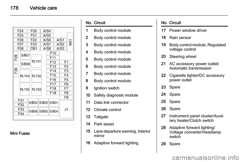
No.Circuit1Body control module2Body control module3Body control module4Body control module5Body control module6Body control module7Body control module8Body control module9Ignition switch10Safety diagnosis module11Data link connector12Climate control13Tailgate14Park assist15Lane departure warning, Interior
mirror16Adaptive forward lightingNo.Circuit17Power window driver18Rain sensor19Body control module, Regulated
voltage control20Steering wheel21AC accessory power outlet/
Automatic transmission22Cigarette lighter/DC accessory
power outlet23Spare24Spare25Spare26Spare27Instrument panel cluster/Auxil‐
iary heater/Clutch switch28Adaptive forward lighting/
Voltage converter/Headlamp
switch29Spare
Page 182 of 229

180Vehicle care
No.Circuit1Seat, lumbar support, driver2Seat, lumbar support,
passenger3Amplifier4Trailer socket5All-wheel drive6Spare7LPG system8Spare9Spare10Spare11Trailer control module12Spare13Heated steering wheel14Trailer socket15Spare16Water in fuel sensorNo.Circuit17Interior mirror/Rear view
camera18LPG system
S/B Fuses
No.Circuit1Power seat driver2Power seat passenger3Trailer control module4Voltage converter5Battery6Headlight washer7Spare8Spare9SpareVehicle tools
Tools
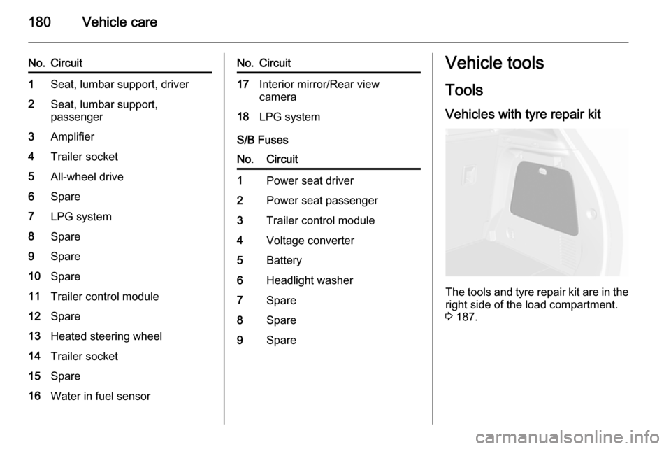
Vehicles with tyre repair kit
The tools and tyre repair kit are in the
right side of the load compartment.
3 187.
Page 189 of 229

Vehicle care187Tyre chains
Use tyre chains only on front wheels.
9Warning
Damage may lead to tyre blowout.
Tyre chains are permitted on tyres of
size 195/70 R16.
Always use fine mesh chains suitable
for sport utility vehicles that add no
more than 12 mm to the tyre tread and the inboard sides (including chain
lock).
On tyres of size 215/55 R18, special
snow chains are only permitted when
they are designed with a rotating
chain belt on the tyre tread, no chain
links on the wheel inboard sides and
the chains add no more than 12 mm
to the tyre tread. For further
information regarding correct snow
chain usage for this tyre size, contact a specialized vehicle parts dealer or
snow chain manufacturer.
Tyre chains are not permitted on tyres of size 205/70 R16, 215/65 R16,
215/60 R17 and 225/45 R19.
The use of tyre chains is not permitted
on the temporary spare wheel.
Tyre repair kit
Minor damage to the tyre tread can be
repaired with the tyre repair kit.
Do not remove foreign bodies from
the tyres.
Tyre damage exceeding 4 mm or that
is at tyre's sidewall cannot be repaired with the tyre repair kit.9 Warning
Do not drive faster than 50 mph.
Do not use for a lengthy period.
Steering and handling may be
affected.
If you have a flat tyre:
Apply the parking brake and engage
first gear, reverse gear or P.
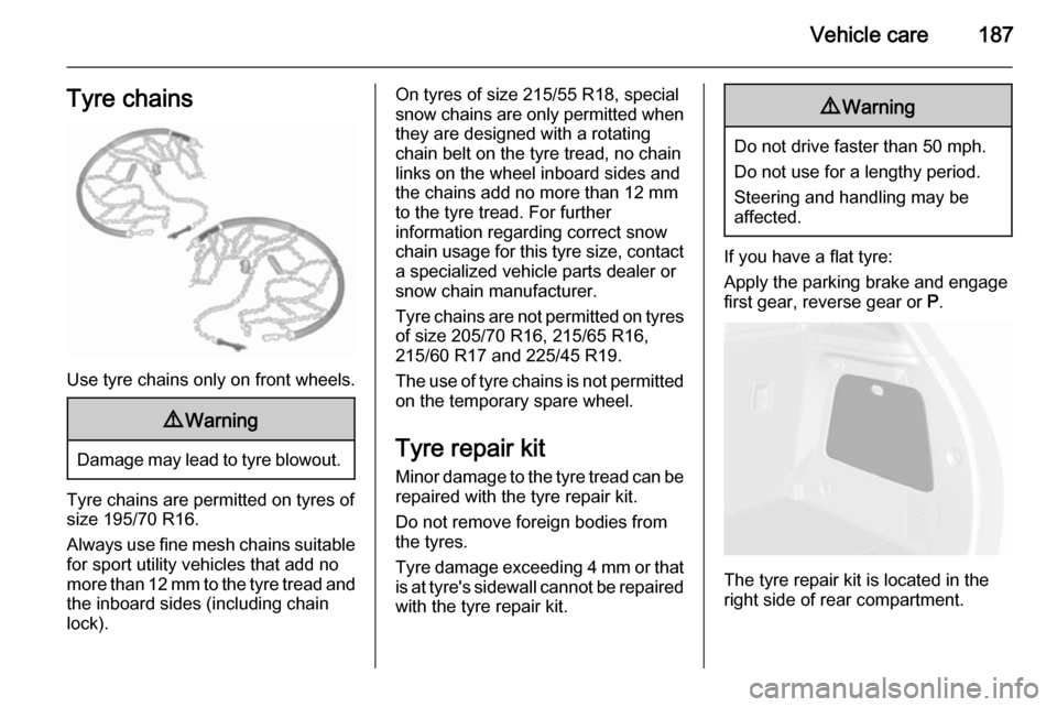
The tyre repair kit is located in the
right side of rear compartment.
Page 198 of 229

196Vehicle care
4. Switch on electrical consumers(e.g. headlights, heated rear
window) of the vehicle receiving
the jump start.
5. Reverse above sequence exactly when removing leads.Towing
Towing the vehicle
Disengage cap by using a
screwdriver and remove.
The towing eye is stowed with the vehicle tools 3 180.
Screw in the towing eye as far as it will
go until it stops in a horizontal
position.
Attach a tow rope – or better still a tow
rod – to the towing eye.
The towing eye must only be used for towing and not for recovering the
vehicle.
Switch on ignition to release steering
wheel lock and to permit operation of
brake lights, horn and windscreen
wiper.
Transmission in neutral.