control VAUXHALL MOKKA 2015 Manual Online
[x] Cancel search | Manufacturer: VAUXHALL, Model Year: 2015, Model line: MOKKA, Model: VAUXHALL MOKKA 2015Pages: 223, PDF Size: 6.2 MB
Page 149 of 223

Driving and operating147signs. Do not ignore traffic signs
which are not displayed by the
system.
The system does not recognise
any other than the conventional
traffic signs that might give or end
a speed limit.
Do not let this special feature
tempt you into taking risks when
driving.
Always adapt speed to the road
conditions.
The driver assistance systems do not relieve the driver from full
responsibility for vehicle
operation.
Lane departure warning
The lane departure warning systemobserves the lane markings between
which the vehicle is driving via a front camera. The system detects lane
changes and warns the driver in the
event of an unintended lane change
via visual and acoustic signals.
Criteria for the detection of an
unintended lane change are:
■ no operation of turn signals
■ no brake pedal operation
■ no active accelerator operation or speeding-up
■ no active steering
If the driver is active, no warning will
be issued.
Activation
The lane departure warning system is activated by pressing the ) button.
The illuminated LED in the button
indicates that the system is switched
on. When the control indicator ) in
the instrument cluster illuminates
green, the system is ready to operate.
The system is only operable at
vehicle speeds above 35 mph and if
lane markings are available.
When the system recognises an
unintended lane change, the control
indicator ) changes to yellow and
flashes. Simultaneously a chime
sound is activated.
Deactivation
The system is deactivated by
pressing ) button, the LED in the
button extinguishes.
Page 150 of 223

148Driving and operating
At speeds below 35 mph the system
is inoperable.
Fault
The lane departure warning system
may not operate properly when:
■ the windscreen is not clean
■ there are adverse environmental conditions like heavy rain, snow,
direct sunlight or shadows
The system can not operate when no
lane marking is detected.Fuel
Fuel for petrol enginesOnly use unleaded fuel that complies
with European standard EN 228 or
E DIN 51626-1 or equivalent.
Your engine is capable to run with
E10 fuel that fulfills these standards.
E10 fuel contains up to 10 %
bioethanol.
Use fuel with the recommended
octane rating 3 205. Use of fuel with
too low an octane rating can reduce
engine power and torque and slightly increases fuel consumption.Caution
Do not use fuel or fuel additives
that contain metallic compounds
such as manganese-based
additives. This may cause engine
damage.
Caution
Use of fuel that does not comply to EN 228 or E DIN 51626-1 or
equivalent can lead to deposits or
engine damage and may affect
your warranty.
Caution
Use of fuel with too low an octane
rating could lead to uncontrolled combustion and engine damage.
Fuel for diesel engines
Only use diesel fuel that complies
with EN 590.
In countries outside the European
Union use Euro-Diesel fuel with a
sulphur concentration below 50 ppm.
Page 151 of 223

Driving and operating149Caution
Use of fuel that does not comply toEN 590 or similar can lead to
engine powerloss, increased wear
or engine damage and loss of
warranty.
Do not use marine diesel oils, heating
oils, Aquazole and similar diesel-
water emulsions. Diesel fuels must
not be diluted with fuels for petrol
engines.
Fuel for liquid gas
operation
Liquid gas is known as LPG
(Liquefied Petroleum Gas) or under
its French name GPL (Gaz de Pétrole Liquéfié). LPG is also known as
Autogas.
LPG consists mainly of propane and
butane. The octane rating is between
105 and 115, depending on the
butane proportion. LPG is stored
liquid at around 5 - 10 bar pressure.
The boiling point depends on the
pressure and mixing ratio. At ambient pressure, it is between -42 °C (pure
propane) and -0.5 °C (pure butane).Caution
The system works at an ambient
temperature of approx. -8 °C to
100 °C.
Full function of the LPG system can
only be guaranteed with liquid gas
which complies with the minimum
requirements of DIN EN 589.
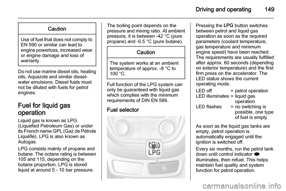
Fuel selector
Pressing the LPG button switches
between petrol and liquid gas
operation as soon as the required
parameters (coolant temperature,
gas temperature and minimum
engine speed) have been reached.
The requirements are usually fulfilled
after approx. 60 seconds (depending
on exterior temperature) and the first
firm press on the accelerator. The
LED status shows the current
operating mode.LED off=petrol operationLED illuminates=liquid gas
operationLED flashes=no switching is
possible, one type
of fuel is empty
As soon as the liquid gas tanks are empty, petrol operation is
automatically engaged until the
ignition is switched off.
Every six months, run the petrol tank down until control indicator i
illuminates, then refuel. This helps
maintain fuel quality and system
function for petrol operation.
Page 158 of 223

156Vehicle careVehicle careGeneral Information...................156
Vehicle checks ........................... 157
Bulb replacement .......................164
Electrical system ........................170
Vehicle tools .............................. 175
Wheels and tyres .......................176
Jump starting ............................. 189
Towing ....................................... 191
Appearance care .......................193General Information
Accessories and vehicle
modifications
We recommend the use of genuine parts and accessories and factory
approved parts specific for your
vehicle type. We cannot assess or
guarantee reliability of other products
- even if they have a regulatory or
otherwise granted approval.
Do not make any modifications to the electrical system, e.g. changes of
electronic control units (chip tuning).Caution
When transporting the vehicle on
a train or on a recovery vehicle, the
mud flaps might be damaged.
Vehicle storage
Storage for a long period of time
If the vehicle is to be stored for several months:
■ Wash and wax the vehicle.
■ Have the wax in the engine compartment and underbody
checked.
■ Clean and preserve the rubber seals.
■ Fill up fuel tank completely.
■ Change the engine oil.
■ Drain the washer fluid reservoir.
■ Check the coolant antifreeze and corrosion protection.
■ Adjust tyre pressure to the value specified for full load.
■ Park the vehicle in a dry, well ventilated place. Engage first orreverse gear or set selector lever to P . Prevent the vehicle from rolling.
■ Do not apply the parking brake.
Page 173 of 223

Vehicle care171
Fuse extractorA fuse extractor may be located in the fuse box in the engine compartment.
Place the fuse extractor on the
various types of use from the top or
side, and withdraw fuse.
Engine compartment fuse
box
The fuse box is in the engine
compartment.
Disengage the cover, lift it upwards
and remove.
Mini Fuses
No.Circuit1Sunroof2Exterior mirrors3–4–5Electrical brake control module6Intelligent battery sensor7–8Transmission control module9Body control module10Headlight levelling11Rear window wiper12Heated rear window13Headlight actuator (left hand)14Heated exterior mirrors15–16Seat heating17Transmission control module
Page 174 of 223

172Vehicle care
No.Circuit18Engine control module19Fuel pump20–21Cooling fan22–23Ignition coil, Engine control
module24Washer pump25Headlamp actuator (right hand)26Engine control module27–28Engine control module29Engine control module30Exhaust system31Left-hand high beam32Right-hand high beam33Engine control moduleNo.Circuit34Horn35Climate control, air conditioning
system36Front fog lamp
J-cases Fuses
No.Circuit1Electrical brake control module2Front wiper3Engine control module4Engine control module5–6Fuel heater7–8Cooling fan9Cooling fanNo.Circuit10Engine control module, Glow
plug11Starter
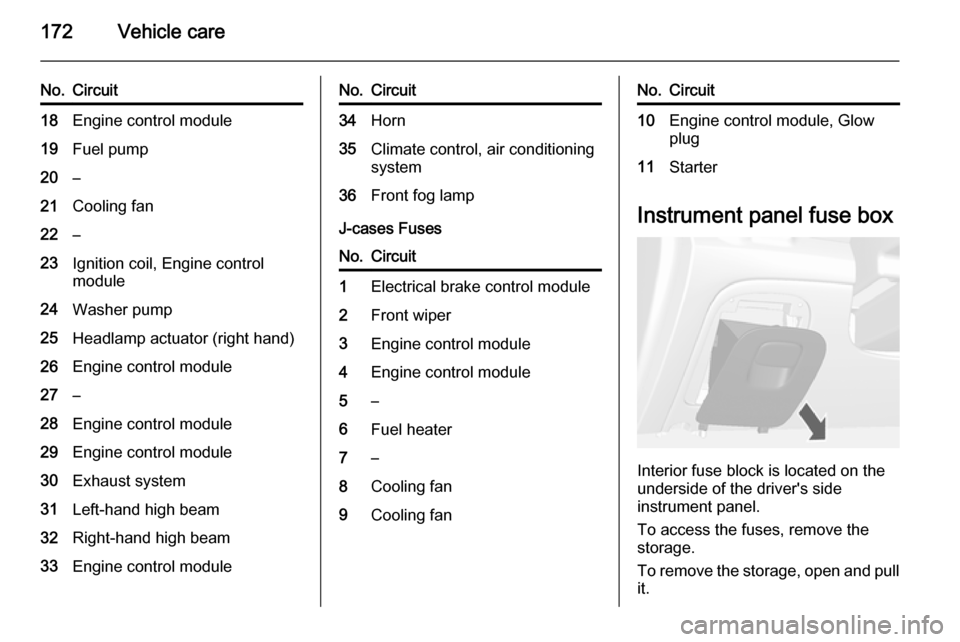
Instrument panel fuse box
Interior fuse block is located on the
underside of the driver's side
instrument panel.
To access the fuses, remove the
storage.
To remove the storage, open and pull it.
Page 175 of 223

Vehicle care173
Mini Fuses
No.Circuit1Body control module2Body control module3Body control module4Body control module5Body control module6Body control module7Body control module8Body control module9Door locks10Safety diagnosis module11Door locks12Climate control13Tailgate14Park assist15Lane departure warning, Interior
mirror16Adaptive forward lightingNo.Circuit17Power window driver18Rain sensor19Spare20Steering wheel21Transmission control module22Cigarette lighter23Spare24Spare25Spare26Display27Instrument panel cluster28Adaptive forward lighting29Spare30Spare31Instrument panel cluster32Infotainment, auxiliary, power
outlet
Page 177 of 223

Vehicle care175
No.Circuit1LPG system2Interior mirror, rear view camera3Water in fuel sensor4Spare5Trailer socket6Heated steering wheel7Spare8Trailer control module9Seat, lumbar support, driver10Seat, lumbar support,
passenger11Amplifier12Trailer socket13All-wheel drive14Spare15LPG system16SpareNo.Circuit17Spare18Spare
S/B Fuses
No.Circuit19Power seat driver20Power seat passenger21Trailer control module22Voltage converter23Ignition system24Headlight washer25Spare26Spare27SpareVehicle tools
Tools
Vehicles with tyre repair kit
The tools and tyre repair kit are in the
right side of the load compartment.
3 182.
Page 180 of 223

178Vehicle care
All wheels must be equipped with
pressure sensors and the tyres must
have the prescribed pressure.
Notice
In countries where the tyre pressure monitoring system is legally
required, the use of wheels without
pressure sensors will invalidate the
vehicle type approval.
The current tyre pressures can be
shown in the Vehicle Information
Menu in the Driver Information Centre
(DIC).
The menu can be selected by the
buttons on the turn signal lever.Press the MENU button to select the
Vehicle Information Menu X .
Turn the adjuster wheel to select the
tyre pressure monitoring system.
System status and pressure warnings
are displayed by a message with the
corresponding tyre flashing in the
DIC.
A detected low tyre pressure
condition is indicated by the control
indicator w 3 87.
If w illuminates, stop as soon as
possible and inflate the tyres as
recommended 3 210.
If w flashes for 60-90 seconds and
then illuminates continuously, there is a fault in the system. Consult a
workshop.
After inflating, driving may be
required to update the tyre pressure
values in the DIC. During this time w
may illuminate.
Page 181 of 223

Vehicle care179
If w illuminates at lower temperatures
and extinguishes after some driving,
this could be an indicator for getting
low pressure. Check tyre pressure.
Vehicle messages 3 95.
If the tyre pressure shall be reduced
or increased, switch off ignition.
Only mount wheels with pressure
sensors, otherwise the tyre pressure
will not be displayed and w
illuminates continuously.
A temporary spare wheel is not
equipped with pressure sensors. The
tyre pressure monitoring system is
not operational for these wheels.
Control indicator w illuminates. For
the further three wheels the system
remains operational.
The use of commercially available
liquid tyre repair kits can impair the
function of the system. Factory-
approved repair kits can be used.
External high-power radio equipment
could disrupt the tyre pressure
monitoring system.Each time the tyres are replaced tyre
pressure monitoring system sensors
must be dismounted and serviced. For the screwed sensor: replace
valve core and sealing ring. For
clipped sensor: replace complete
valve stem.
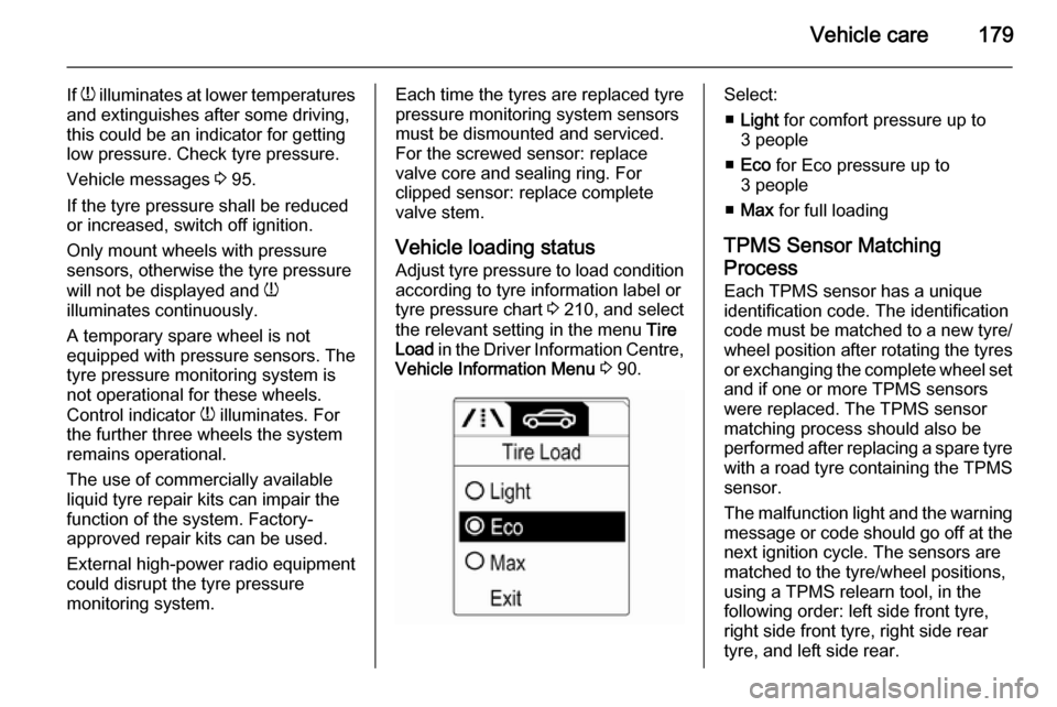
Vehicle loading status
Adjust tyre pressure to load condition according to tyre information label or
tyre pressure chart 3 210, and select
the relevant setting in the menu Tire
Load in the Driver Information Centre,
Vehicle Information Menu 3 90.Select:
■ Light for comfort pressure up to
3 people
■ Eco for Eco pressure up to
3 people
■ Max for full loading
TPMS Sensor Matching
Process
Each TPMS sensor has a unique
identification code. The identification
code must be matched to a new tyre/
wheel position after rotating the tyres
or exchanging the complete wheel set and if one or more TPMS sensors
were replaced. The TPMS sensor matching process should also be
performed after replacing a spare tyre
with a road tyre containing the TPMS
sensor.
The malfunction light and the warning
message or code should go off at the
next ignition cycle. The sensors are
matched to the tyre/wheel positions,
using a TPMS relearn tool, in the
following order: left side front tyre,
right side front tyre, right side rear
tyre, and left side rear.