lock VAUXHALL MOKKA 2016.5 User Guide
[x] Cancel search | Manufacturer: VAUXHALL, Model Year: 2016.5, Model line: MOKKA, Model: VAUXHALL MOKKA 2016.5Pages: 231, PDF Size: 6.57 MB
Page 26 of 231

24Keys, doors and windowsSettings can be changed in the menuSettings in the Info-Display. Vehicle
personalisation 3 99.
The settings can be saved for the key being used 3 21.
Child locks9 Warning
Use the child locks whenever
children are occupying the rear
seats.
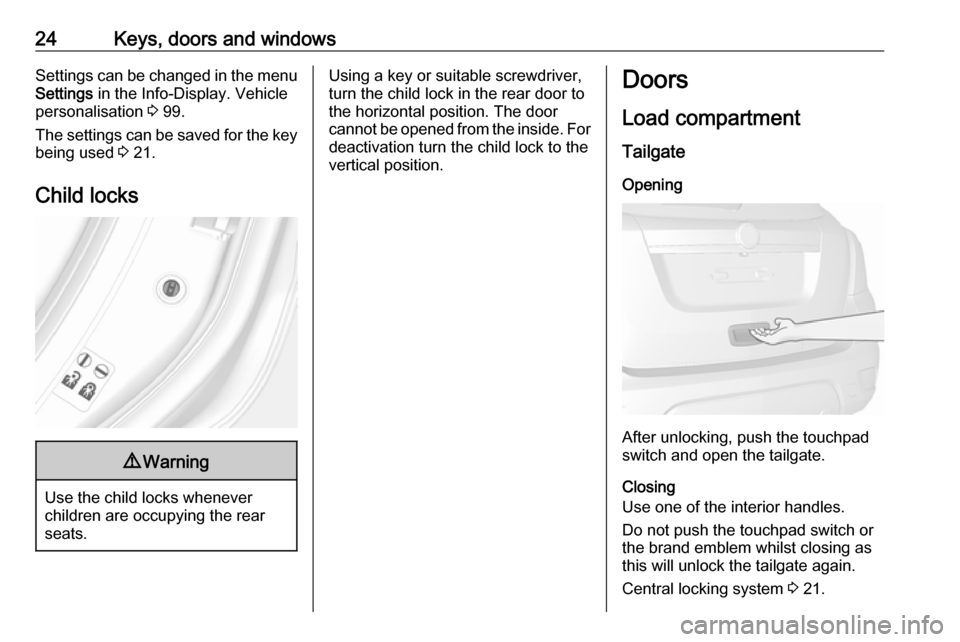
Using a key or suitable screwdriver,
turn the child lock in the rear door to
the horizontal position. The door
cannot be opened from the inside. For
deactivation turn the child lock to the
vertical position.Doors
Load compartment Tailgate
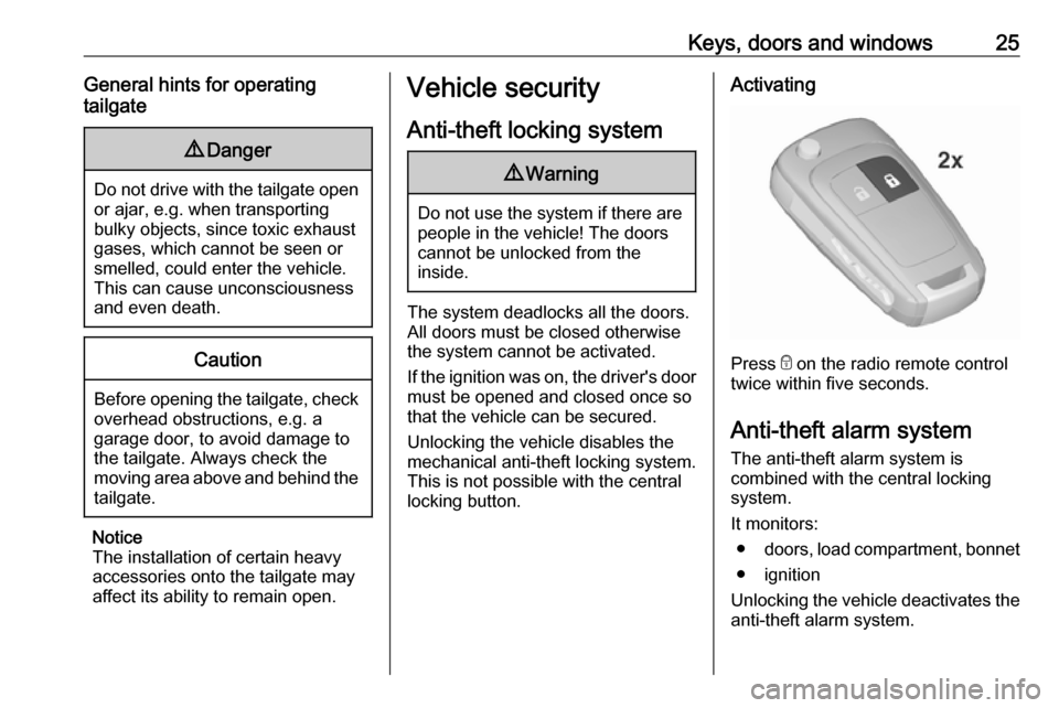
Opening
After unlocking, push the touchpad
switch and open the tailgate.
Closing
Use one of the interior handles.
Do not push the touchpad switch or
the brand emblem whilst closing as
this will unlock the tailgate again.
Central locking system 3 21.
Page 27 of 231

Keys, doors and windows25General hints for operating
tailgate9 Danger
Do not drive with the tailgate open
or ajar, e.g. when transporting
bulky objects, since toxic exhaust
gases, which cannot be seen or
smelled, could enter the vehicle.
This can cause unconsciousness
and even death.
Caution
Before opening the tailgate, check overhead obstructions, e.g. a
garage door, to avoid damage to
the tailgate. Always check the
moving area above and behind the
tailgate.
Notice
The installation of certain heavy
accessories onto the tailgate may
affect its ability to remain open.
Vehicle security
Anti-theft locking system9 Warning
Do not use the system if there are
people in the vehicle! The doorscannot be unlocked from the
inside.
The system deadlocks all the doors. All doors must be closed otherwise
the system cannot be activated.
If the ignition was on, the driver's door
must be opened and closed once so
that the vehicle can be secured.
Unlocking the vehicle disables the
mechanical anti-theft locking system.
This is not possible with the central
locking button.
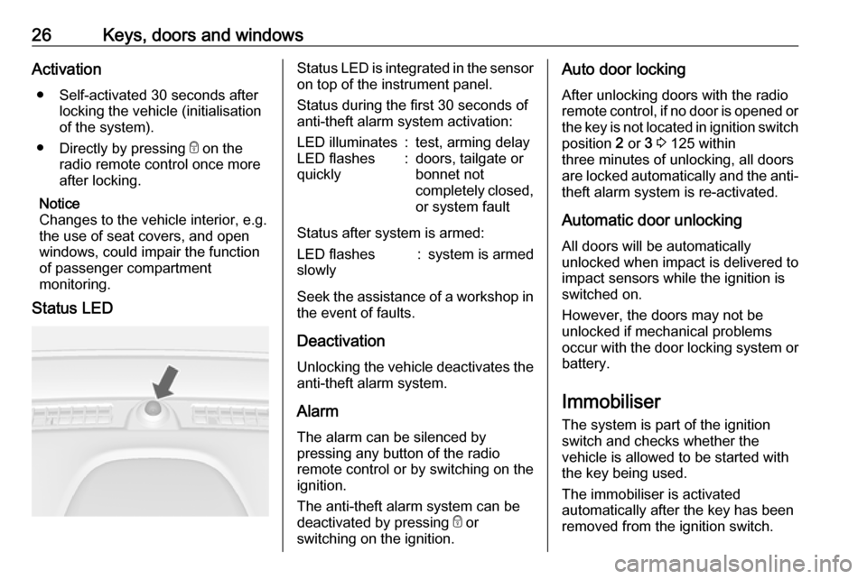
Activating
Press e on the radio remote control
twice within five seconds.
Anti-theft alarm system The anti-theft alarm system is
combined with the central locking
system.
It monitors: ● doors, load compartment, bonnet
● ignition
Unlocking the vehicle deactivates the anti-theft alarm system.
Page 28 of 231

26Keys, doors and windowsActivation● Self-activated 30 seconds after locking the vehicle (initialisation
of the system).
● Directly by pressing e on the
radio remote control once more
after locking.
Notice
Changes to the vehicle interior, e.g.
the use of seat covers, and open
windows, could impair the function
of passenger compartment
monitoring.
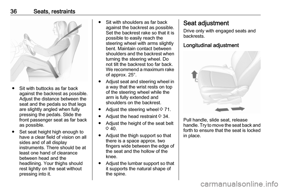
Status LEDStatus LED is integrated in the sensor
on top of the instrument panel.
Status during the first 30 seconds of
anti-theft alarm system activation:LED illuminates:test, arming delayLED flashes
quickly:doors, tailgate or
bonnet not
completely closed,
or system fault
Status after system is armed:
LED flashes
slowly:system is armed
Seek the assistance of a workshop in the event of faults.
Deactivation Unlocking the vehicle deactivates the
anti-theft alarm system.
Alarm The alarm can be silenced bypressing any button of the radio
remote control or by switching on the
ignition.
The anti-theft alarm system can be
deactivated by pressing e or
switching on the ignition.
Auto door locking
After unlocking doors with the radio
remote control, if no door is opened or
the key is not located in ignition switch position 2 or 3 3 125 within
three minutes of unlocking, all doors
are locked automatically and the anti-
theft alarm system is re-activated.
Automatic door unlocking All doors will be automatically
unlocked when impact is delivered to
impact sensors while the ignition is
switched on.
However, the doors may not be
unlocked if mechanical problems
occur with the door locking system or
battery.
Immobiliser
The system is part of the ignition
switch and checks whether the
vehicle is allowed to be started with the key being used.
The immobiliser is activated
automatically after the key has been
removed from the ignition switch.
Page 29 of 231

Keys, doors and windows27If the control indicator d flashes when
the ignition is on, there is a fault in the
system; the engine cannot be started. Switch off the ignition and repeat the
start attempt.
If the control indicator continues
flashing, attempt to start the engine
using the spare key and seek the
assistance of a workshop.
Notice
The immobiliser does not lock the
doors. You should always lock the
vehicle after leaving it and switch on the anti-theft alarm system 3 21,
3 25.
Control indicator d 3 87.Exterior mirrors
Convex shape
The convex exterior mirror contains
an aspherical area and reduces blind spots. The shape of the mirror makes objects appear smaller, which will
affect the ability to estimate
distances.
Electric adjustment
Select the relevant exterior mirror by
turning the control to left (L) or right
(R) . Then swivel the control to adjust
the mirror.
In position 0 no mirror is selected.
Folding mirrors
Manual folding
For pedestrian safety, the exterior
mirrors will swing out of their normal
mounting position if they are struck
with sufficient force. Reposition the mirror by applying slight pressure tothe mirror housing.
Page 38 of 231

36Seats, restraints
● Sit with buttocks as far backagainst the backrest as possible.
Adjust the distance between the
seat and the pedals so that legs
are slightly angled when fully
pressing the pedals. Slide the
front passenger seat as far back
as possible.
● Set seat height high enough to have a clear field of vision on all
sides and of all display
instruments. There should be at
least one hand of clearance
between head and the
headlining. Your thighs should
rest lightly on the seat without
pressing into it.
● Sit with shoulders as far back against the backrest as possible.
Set the backrest rake so that it is possible to easily reach the
steering wheel with arms slightly
bent. Maintain contact between
shoulders and the backrest when
turning the steering wheel. Do
not tilt the backrest too far back.
We recommend a maximum rake of approx. 25°.
● Adjust seat and steering wheel in
a way that the wrist rests on top
of the steering wheel while the
arm is fully extended and
shoulders on the backrest.
● Adjust the steering wheel 3 71.
● Adjust the head restraint 3 34.
● Adjust the height of the seat belt 3 40.
● Adjust the thigh support so that there is a space approx. two
fingers wide between the edge of the seat and the hollow of the
knee.
● Adjust the lumbar support so that
it supports the natural shape of
the spine.Seat adjustment
Drive only with engaged seats and backrests.
Longitudinal adjustment
Pull handle, slide seat, release
handle. Try to move the seat back and forth to ensure that the seat is locked
in place.
Page 41 of 231

Seats, restraints39Seat belts
The seat belts are locked during
heavy acceleration or deceleration of
the vehicle holding the occupants in
the sitting position. Therefore the risk
of injury is considerably reduced.
9 Warning
Fasten seat belt before each trip.
In the event of an accident, people
not wearing seat belts endanger their fellow occupants and
themselves.
Seat belts are designed to be used by only one person at a time. Child
restraint system 3 48.
Periodically check all parts of the belt
system for damage and proper
functionality.
Have damaged components
replaced. After an accident, have the
belts and triggered belt pretensioners replaced by a workshop.
Notice
Make sure that the belts are not
damaged by shoes or sharp-edged
objects or are trapped. Prevent dirt
from getting into the belt retractors.
Seat belt reminder X 3 83.
Belt force limiters
On the front seats, stress on the body is reduced by the gradual release of
the belt during a collision.
Belt pretensioners
In the event of a head-on or rear-end
collision of a certain severity, the front seat belts are tightened.9 Warning
Incorrect handling ( e.g. removal or
fitting of belts) can trigger the belt
pretensioners.
Deployment of the belt pretensioners
is indicated by continuous illumination
of control indicator v 3 83.
Triggered belt pretensioners must be
replaced by a workshop. Belt
pretensioners can only be triggered
once.
Notice
Do not affix or install accessories or
other objects that may interfere with
the operation of the belt
pretensioners. Do not make any
modifications to belt pretensioner
components as this will invalidate
the vehicle type approval.
Page 61 of 231

Storage59Remove strap and fold out the wheel
recess.
Lock the rear carrier system
Remove strap and swivel both
clamping levers sidewards as far as
they will go.
Otherwise safe functionality is not
guaranteed.
Assembling the bicycle rack
Lift the rack at the rear ( 1) and pull it
backwards.
Fold up the rack ( 2).
Push down the rack ( 1) and swivel
handle ( 2) backwards to engage.
Press button ( 1) and remove left part
of rack ( 2).
Press button ( 1) and insert left part of
rack into the right part ( 2).
Page 62 of 231

60Storage
Attaching a bicycle
1.Rotate the pedals into position, as
shown in the illustration, and put
the bicycle on the wheel recess.
Make sure that the bicycle stands centrally on the wheel recesses.
2. Attach the short mounting bracket
to the bicycle frame. Turn the
knob clockwise to fasten.
3. Secure both bicycle wheels to the
wheel recesses using the strap
retainers.
4. Check the bicycle to make sure it is secure.Caution
Ensure gap between bicycle and
vehicle is at least 5 cm. If
necessary, loosen handlebar and swivel sideways.
Attaching the adapter
When carrying more than one bicycle, the adapter must be fixed.
Page 65 of 231

Storage63To increase visibility, the tail lights of
the vehicle are activated when the
rear carrier system is folded back.9 Warning
When folding the rear carrier
system forwards again, take care that the system is engaged
securely.
Removing bicycles
Undo strap retainers on both bicycle
tyres.
Turn knob anticlockwise and remove
mounting brackets.
Detaching adapter
Detach the adapter before removing
the bicycle on the rear carrier system.
1. Fold in wheel recesses.
2. Unbutton the strap.
3. Turn the lever ( 1) forwards and
hold.
4. Lift the adapter ( 2) at the rear and
remove.
Disassembling the bicycle rack
Press button ( 1) and remove upper
part of rack ( 2).
Press button ( 1) and reinstall rack ( 2).
Page 66 of 231

64Storage
Arrange mounting brackets as shownin the illustration.
Swivel handle ( 1) sidewards to
disengage and lift the rack ( 2).
Fold the rack backwards, then push
forwards until it stops ( 1).
Press the rack down at the rear ( 2).
Fold in wheel recess
Fold in wheel recess. Fasten strap.
Stow the strap retainers accurately.
Unlock the rear carrier system
Swivel both clamping levers inwards
as far as they will go. Fasten strap.
Fold in tail lamps
Remove both screws. Pull tail lamps
out of the retainer and swivel them
forwards.
Push the tail lamps into the retainer
and reinstall screws to fix the lamps
Fold in number plate holder
Lift the number plate holder and fold
it forwards.