mirror VAUXHALL MOVANO_B 2014 Owner's Manual
[x] Cancel search | Manufacturer: VAUXHALL, Model Year: 2014, Model line: MOVANO_B, Model: VAUXHALL MOVANO_B 2014Pages: 201, PDF Size: 4.74 MB
Page 10 of 201
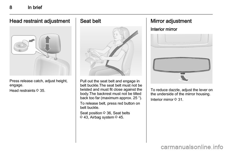
8In briefHead restraint adjustment
Press release catch, adjust height,
engage.
Head restraints 3 35.
Seat belt
Pull out the seat belt and engage in
belt buckle.The seat belt must not be twisted and must fit close against the
body.The backrest must not be tilted
back too far (maximum approx. 25 °).
To release belt, press red button on
belt buckle.
Seat position 3 36, Seat belts
3 43, Airbag system 3 45.
Mirror adjustment
Interior mirror
To reduce dazzle, adjust the lever on the underside of the mirror housing.
Interior mirror 3 31.
Page 11 of 201
In brief9
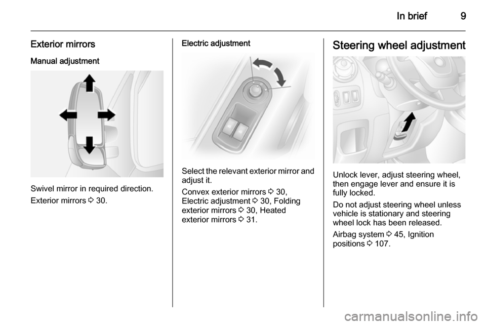
Exterior mirrors
Manual adjustment
Swivel mirror in required direction.
Exterior mirrors 3 30.
Electric adjustment
Select the relevant exterior mirror and
adjust it.
Convex exterior mirrors 3 30,
Electric adjustment 3 30, Folding
exterior mirrors 3 30, Heated
exterior mirrors 3 31.
Steering wheel adjustment
Unlock lever, adjust steering wheel,
then engage lever and ensure it is fully locked.
Do not adjust steering wheel unless
vehicle is stationary and steering
wheel lock has been released.
Airbag system 3 45, Ignition
positions 3 107.
Page 16 of 201
14In briefWasher and wiper systems
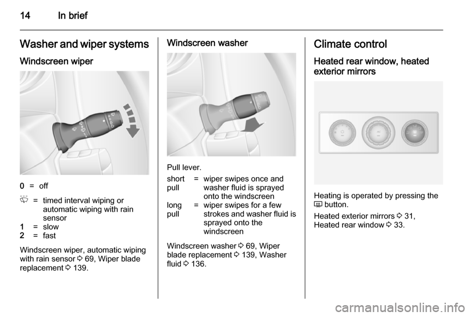
Windscreen wiper0=offP=timed interval wiping or
automatic wiping with rain
sensor1=slow2=fast
Windscreen wiper, automatic wiping
with rain sensor 3 69, Wiper blade
replacement 3 139.
Windscreen washer
Pull lever.
short
pull=wiper swipes once and
washer fluid is sprayed
onto the windscreenlong
pull=wiper swipes for a few
strokes and washer fluid is
sprayed onto the
windscreen
Windscreen washer 3 69, Wiper
blade replacement 3 139, Washer
fluid 3 136.
Climate control
Heated rear window, heatedexterior mirrors
Heating is operated by pressing the
Ü button.
Heated exterior mirrors 3 31,
Heated rear window 3 33.
Page 18 of 201
16In brief
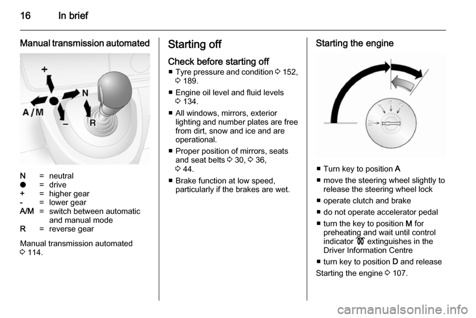
Manual transmission automatedN=neutralo=drive+=higher gear-=lower gearA/M=switch between automatic
and manual modeR=reverse gear
Manual transmission automated
3 114.
Starting off
Check before starting off ■ Tyre pressure and condition 3 152,
3 189.
■ Engine oil level and fluid levels 3 134.
■ All windows, mirrors, exterior lighting and number plates are free
from dirt, snow and ice and are
operational.
■ Proper position of mirrors, seats and seat belts 3 30, 3 36,
3 44.
■ Brake function at low speed, particularly if the brakes are wet.Starting the engine
■ Turn key to position A
■ move the steering wheel slightly to release the steering wheel lock
■ operate clutch and brake
■ do not operate accelerator pedal
■ turn the key to position M for
preheating and wait until control
indicator ! extinguishes in the
Driver Information Centre
■ turn key to position D and release
Starting the engine 3 107.
Page 20 of 201
18Keys, doors and windowsKeys, doors and
windowsKeys, locks ................................... 18
Doors ........................................... 24
Vehicle security ............................ 27
Exterior mirrors ............................ 30
Interior mirrors ............................. 31
Windows ...................................... 32
Roof ............................................. 34Keys, locks
Keys Replacement keys
The key number is specified in the
Car Pass or on a detachable tag.
The key number must be quoted
when ordering replacement keys as it
is a component of the immobiliser
system.
Locks 3 164.
Car Pass The Car Pass contains security
related vehicle data and should
therefore be kept in a safe place.
When the vehicle is taken to a
workshop, this vehicle data is needed
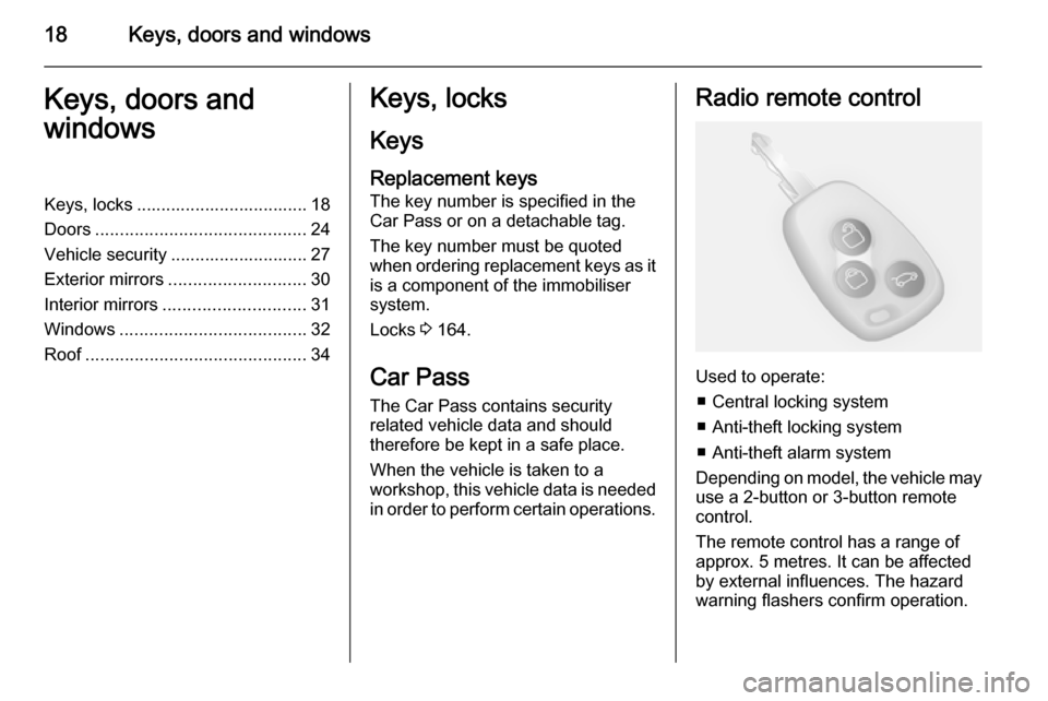
in order to perform certain operations.Radio remote control
Used to operate:
■ Central locking system
■ Anti-theft locking system
■ Anti-theft alarm system
Depending on model, the vehicle may use a 2-button or 3-button remote
control.
The remote control has a range of
approx. 5 metres. It can be affected
by external influences. The hazard
warning flashers confirm operation.
Page 32 of 201
30Keys, doors and windowsExterior mirrors
Convex shape
The convex exterior mirror contains
an aspherical area and reduces blind spots. The shape of the mirror makes
objects appear smaller, which will
affect the ability to estimate
distances.
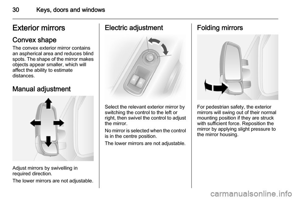
Manual adjustment
Adjust mirrors by swivelling in
required direction.
The lower mirrors are not adjustable.
Electric adjustment
Select the relevant exterior mirror by
switching the control to the left or
right, then swivel the control to adjust
the mirror.
No mirror is selected when the control is in the centre position.
The lower mirrors are not adjustable.
Folding mirrors
For pedestrian safety, the exterior
mirrors will swing out of their normal
mounting position if they are struck
with sufficient force. Reposition the mirror by applying slight pressure tothe mirror housing.
Page 33 of 201
Keys, doors and windows31Heated mirrors
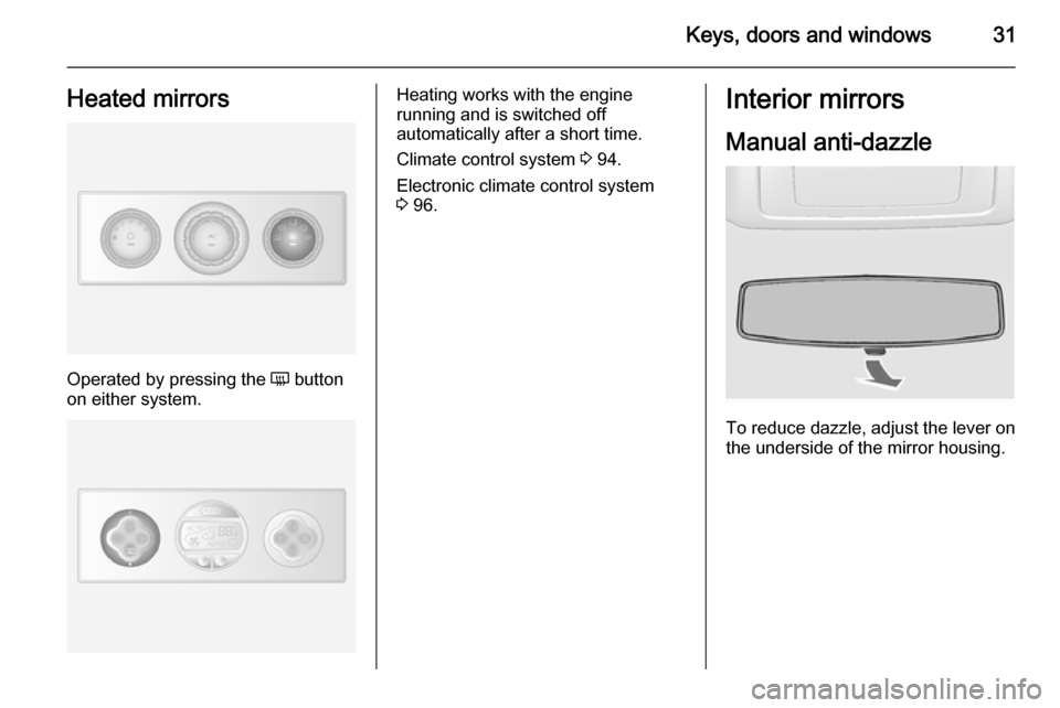
Operated by pressing the Ü button
on either system.
Heating works with the engine
running and is switched off
automatically after a short time.
Climate control system 3 94.
Electronic climate control system 3 96.Interior mirrors
Manual anti-dazzle
To reduce dazzle, adjust the lever on the underside of the mirror housing.
Page 36 of 201
34Keys, doors and windows
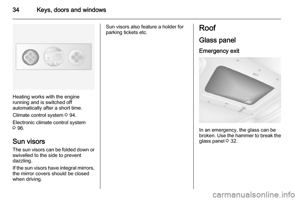
Heating works with the engine
running and is switched off
automatically after a short time.
Climate control system 3 94.
Electronic climate control system 3 96.
Sun visors The sun visors can be folded down orswivelled to the side to prevent
dazzling.
If the sun visors have integral mirrors, the mirror covers should be closed
when driving.
Sun visors also feature a holder for
parking tickets etc.Roof
Glass panel
Emergency exit
In an emergency, the glass can be
broken. Use the hammer to break the
glass panel 3 32.
Page 128 of 201
126Driving and operating
FaultIf the system detects an operatingfault, a continuous acoustic alarm will sound for approx. 5 seconds when
selecting reverse gear. Consult a
workshop to have the cause of the
fault remedied.Caution
When reversing, the area should
be free from obstacles which could impact on the underside of the
vehicle.
Impact to the rear axle, which may
not be visible, could lead to
uncharacteristic changes in the
vehicle handling. In the event of
such an impact, consult a
workshop.
Rear view camera
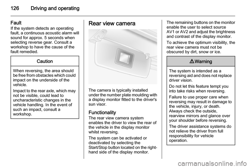
The camera is typically installed
under the number plate moulding with a display monitor fitted to the driver's
sun visor.
Functionality
The rear view camera system
enables the driver to view the rear of
the vehicle in the display monitor
whilst reversing.
The system can be activated or
deactivated by selecting the
Start/Stop button located on the right-
hand side of the display monitor.
The remaining buttons on the monitor enable the user to select source
AV1 or AV2 and adjust the brightness
and contrast of the display monitor.
To achieve the optimum visibility, the
rear view camera must not be
obscured by dirt, snow or ice.9 Warning
The system is intended as a
reversing aid and does not replace
driver vision.
Do not let this feature tempt you
into take risks when reversing.
Failure to use proper care when
reversing may result in damage to
the vehicle, injury, or death.
Always check the outside,
rearview mirrors and glance over
your shoulder before reversing.
The driver assistance systems do not relieve the driver from full
responsibility for vehicle
operation.
Page 147 of 201
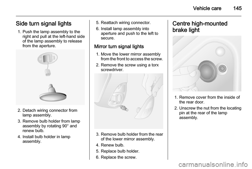
Vehicle care145Side turn signal lights1. Push the lamp assembly to the right and pull at the left-hand sideof the lamp assembly to release
from the aperture.
2. Detach wiring connector from lamp assembly.
3. Remove bulb holder from lamp assembly by rotating 90° and
renew bulb.
4. Install bulb holder in lamp assembly.
5. Reattach wiring connector.
6. Install lamp assembly into aperture and push to the left to
secure.
Mirror turn signal lights 1. Move the lower mirror assembly from the front to access the screw.
2. Remove the screw using a torx screwdriver.
3. Remove bulb holder from the rear
of the lower mirror assembly.
4. Renew bulb.
5. Replace bulb holder.
6. Replace the screw.
Centre high-mounted
brake light
1. Remove cover from the inside of the rear door.
2. Unscrew the nut from the locating
pin at the rear of the lamp
assembly.