tow VAUXHALL MOVANO_B 2018 Owner's Guide
[x] Cancel search | Manufacturer: VAUXHALL, Model Year: 2018, Model line: MOVANO_B, Model: VAUXHALL MOVANO_B 2018Pages: 261, PDF Size: 6.3 MB
Page 155 of 261

Driving and operating153Interruption of power supplyThe clutch is not disengaged if there
is an interruption of the power supply
when a gear is engaged. The vehicle
cannot move.
If the vehicle battery is discharged,
start the vehicle using jump leads
3 212.
If the cause of the fault is not a
discharged vehicle battery, seek the
assistance of a workshop.
If neutral cannot be selected, the
vehicle must only be towed with the
drive wheels raised off the ground
3 214.
Towing the vehicle 3 214.Brakes
The brake system comprises two
independent brake circuits.
If a brake circuit fails, the vehicle can
still be braked using the other brake
circuit. However, braking effect is
achieved only when you depress the
brake pedal firmly. You need to use
considerably more force for this. The
braking distance is extended. Seek
the assistance of a workshop before
continuing your journey.
When the engine is not running, the
support of the brake servo unit
disappears once the brake pedal has been depressed once or twice.
Braking effect is not reduced, but
braking requires significantly greater
force. It is especially important to bear this in mind when being towed.
Control indicator R 3 97.
Antilock brake system
Antilock brake system (ABS)
prevents the wheels from locking.ABS starts to regulate brake pressure as soon as a wheel shows a tendency
to lock. The vehicle remains
steerable, even during hard braking.
ABS control is made apparent
through a pulse in the brake pedal
and the noise of the regulation
process.
For optimum braking, keep the brake
pedal fully depressed throughout the
braking process, despite the fact that the pedal is pulsating. Do not reduce
the pressure on the pedal.
Control indicator u 3 97.
Fault
If control indicators u and A
illuminate with the messages CHECK
ABS and CHECK ESP in the Driver
Information Centre, there is a fault in
the ABS. The brake system remains
operational but without ABS
regulation.
Page 172 of 261
170Driving and operatingTrailer hitch
General information
Only use towing equipment that has
been approved for your vehicle.
Entrust fitting of towing equipment at
a later date to a workshop. It may be
necessary to make changes that
affect the cooling system, heat
shields or other equipment.
Driving characteristics and towing tips
In the case of trailers with brakes,
attach the breakaway stopping cable.
Before attaching a trailer, lubricate
the coupling ball. However, do not do so if a stabiliser, which acts on thecoupling ball, is being used to reduce
snaking movements. For trailers with
low driving stability the use of a
stabiliser is recommended.
A maximum speed of 50 mph must
not be exceeded, even in countries
where higher speeds are permitted.If the trailer starts snaking, drive more slowly, do not attempt to correct the
steering and brake sharply if
necessary.
When driving downhill, drive in the
same gear as if driving uphill and
drive at a similar speed.
Adjust tyre pressure to the value
specified for full load 3 244.
Trailer towing
Trailer loads The permissible trailer loads are
vehicle-dependent and engine-
dependent maximum values which
must not be exceeded. The actual
trailer load is the difference between
the actual gross weight of the trailer
and the actual coupling socket load
with the trailer coupled.
The permissible trailer loads are
specified in the vehicle documents. In
general, they are valid for gradients
up to max. 12%.
The permitted trailer load applies up to the specified incline and up to an
altitude of 1000 metres above sealevel. Since engine power decreases
as altitude increases due to the air
becoming thinner, therefore reducing
climbing ability, the permissible gross
train weight also decreases by 10%
for every 1000 metres of additional
altitude. The gross train weight does
not have to be reduced when driving
on roads with slight inclines (less than 8%, e.g. motorways).
The permissible gross train weight
must not be exceeded. This weight is
specified on the identification plate
3 223.
Vertical coupling load
The vertical coupling load is the load
exerted by the trailer on the coupling
ball. It can be varied by changing the
weight distribution when loading the
trailer.
The maximum permissible vertical
coupling load is specified on the
towing equipment identification plate
and in the vehicle documents. Always aim for the maximum load, especially in the case of heavy trailers. The
vertical coupling load should never
fall below 25 kg.
Page 173 of 261

Driving and operating171In the case of trailer loads of
1200 kg or more, the vertical coupling
load should not be less than 50 kg.
Rear axle loadWhen the trailer is coupled and the
towing vehicle fully loaded (including all occupants), the permissible rear
axle load (see identification plate or
vehicle documents) must not be
exceeded.
Towing equipmentCaution
When operating without a trailer,
remove the coupling ball bar.
Towing equipment audible
warning
For vehicles fitted with towing
equipment, when connected to a
trailer the pitch of the audible warning
changes upon operation of the turn
signals.
The pitch of the audible warning will
change if a turn signal light on the
trailer or the towing vehicle fails.
Trailer stability assist
If the system detects snaking
movements, engine power is reduced
and the vehicle/trailer combination is
selectively braked until the snaking ceases. While the system is working,keep steering wheel as still as
possible.
Trailer stability assist (TSA) is a
function of the Electronic Stability
Program (ESP) 3 156.Auxiliary features
Power take-off
Activation
To activate the power take-off, with
the vehicle stationary and the engine
idling:
● Set the gearshift lever to neutral (vehicles with manual
transmission automated:
selector lever in position N).
● Depress the clutch pedal.
Page 175 of 261
Vehicle care173Vehicle careGeneral Information...................174
Accessories and vehicle modifications .......................... 174
Vehicle storage ........................174
End-of-life vehicle recovery .....175
Vehicle checks ........................... 175
Performing work ......................175
Bonnet ..................................... 175
Engine oil ................................. 176
Engine coolant ......................... 178
Power steering fluid .................178
Washer fluid ............................ 179
Brakes ..................................... 180
Brake fluid ............................... 180
Vehicle battery ......................... 180
Diesel fuel filter ........................182
Diesel fuel system bleeding .....183
Wiper blade replacement ........183
Bulb replacement .......................184
Headlights ............................... 184
Adaptive forward lighting .........187
Fog lights ................................. 187
Front turn signal lights .............187
Tail lights ................................. 188
Side turn signal lights ..............190Centre high-mounted brake
light ......................................... 190
Number plate light ...................191
Interior lights ............................ 192
Instrument panel illumination ...193
Electrical system ........................193
Fuses ....................................... 193
Engine compartment fuse box . 194
Instrument panel fuse box .......195
Load compartment fuse box ....196
Vehicle tools .............................. 198
Tools ........................................ 198
Wheels and tyres .......................199
Tyres ....................................... 199
Winter tyres ............................. 199
Tyre designations ....................199
Tyre pressure .......................... 199
Tyre pressure monitoring system .................................... 200
Tread depth ............................. 202
Changing tyre and wheel size . 203 Wheel covers ........................... 203
Tyre chains .............................. 203
Tyre repair kit .......................... 204
Wheel changing .......................207
Spare wheel ............................ 209
Jump starting ............................. 212Towing....................................... 214
Towing the vehicle ...................214
Towing another vehicle ...........215
Appearance care .......................216
Exterior care ............................ 216
Interior care ............................. 218
Page 186 of 261
184Vehicle careLift wiper arm, press retaining clip
towards wiper arm and detach wiper
blade.
Attach the wiper blade slightly angled to the wiper arm and push until it
engages.
Lower wiper arm carefully.Bulb replacement
Ensure the ignition is switched off
completely (the vehicle must not be in
an Autostop 3 135) and turn off the
relevant switch or close the doors.
Only hold a new bulb at the base. Do not touch the bulb glass with bare
hands.
Use only the same bulb type for
replacement.
Bulb check
After a bulb replacement, switch on
the ignition, operate and check the
lights.
Performing work 3 175.Headlights
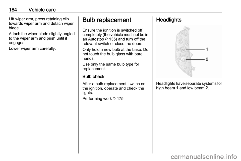
Headlights have separate systems for
high beam 1 and low beam 2.
Page 200 of 261

198Vehicle careVehicle tools
Tools
Vehicles with spare wheel
The jack, wheel wrench, adapters (for
spare wheel removal), hub cap hook
and towing eye are contained in a
unit, stowed under the front seat.
Notice
Depending on vehicle, there may be
multiple adapters for spare wheel
removal.
Vehicles with Rear-wheel drive: A hydraulic jack and a set of extension
pieces for use with the jack are also
included.
Wheel changing 3 207.
Spare wheel 3 209.
Towing the vehicle 3 214.
Vehicles without spare wheel
Some vehicles are equipped with a
tyre repair kit instead of a spare
wheel.
To access this unit, slide the seat fully forwards and fold down the backrest.
If cover is fitted, raise cover slightly
and slide it backwards to remove.
Notice
Do not attempt to remove the unit
from beneath the seat. Risk of injury.
Tyre repair kit 3 204
Page 202 of 261

200Vehicle careThe tyre pressure data refers to cold
tyres. It applies to summer and winter tyres.
Always inflate the spare tyre to the
pressure specified for full load.
Incorrect tyre pressures will impair
safety, vehicle handling, comfort and
fuel economy and will increase tyre
wear.
Tyre pressures differ depending on
various options. For the correct tyre
pressure value, follow the procedure
below:
1. Identify the engine identifier code.
Engine data 3 225.
2. Identify the respective tyre.
The tyre pressure tables show all possible tyre combinations 3 244.
For the tyres approved for your
vehicle, refer to the EEC Certificate of
Conformity provided with your vehicle
or other national registration
documents.
The driver is responsible for correct
adjustment of tyre pressure.9 Warning
If the pressure is too low, this can
result in considerable tyre warm-
up and internal damage, leading to tread separation and even to tyre
blow-out at high speeds.
9 Warning
For specific tyres the
recommended tyre pressure as
shown in the tyre pressure table may exceed the maximum tyre
pressure as indicated on the tyre.
Never exceed the maximum tyre
pressure as indicated on the tyre.
Temperature dependency
Tyre pressure depends on the
temperature of the tyre. During
driving, tyre temperature and
pressure increase.
Tyre pressure values provided on the
tyre information label and tyre
pressure chart are valid for cold tyres, which means at 20 °C. The pressure
increases by nearly 1.5 psi (10 kPa/
0.1 bar) for a 10 °C temperature
increase. This must be considered
when warm tyres are checked.
Trailer towing
When towing a trailer with a fully laden vehicle, the tyre pressure must
be increased by 20 kPa/0.2 bar
(3.0 psi) and the maximum speed
limited to 60 mph.
Trailer towing 3 170.
Rear-wheel drive, with twin rear
wheels
When inflating the outer tyre, the
inflation tube should be passed
between the two wheels.
Tyre pressure monitoringsystem
The tyre pressure monitoring system
uses radio and sensor technology to
check tyre pressure levels.
Page 206 of 261

204Vehicle careAlways use fine mesh chains that addno more than 15 mm to the tyre tread
and the inboard sides (including chain
lock).9 Warning
Damage may lead to tyre blowout.
Wheel covers on steel wheels may
come into contact with parts of the
chains. In such cases, remove the
wheel covers.
Tyre chains may only be used at
speeds up to 30 mph and, when
travelling on roads that are free of
snow, they may only be used for brief
periods since they are subject to rapid wear on a hard road and may snap.
The use of tyre chains is not permitted on the temporary spare wheel or on
wheels of a different size than those
fitted at the factory.
Tyre repair kit Minor damage to the tyre tread can be
repaired with the tyre repair kit.
Do not remove foreign bodies from
the tyres.
Tyre damage exceeding four mm or
that is at the tyre's sidewall near the
rim cannot be repaired with the tyre repair kit.9 Warning
Do not drive faster than 50 mph.
Do not use for a lengthy period.
Steering and handling may be
affected.
If the vehicle has a flat tyre:
Apply the parking brake and engage
neutral (manual transmission) or N
(manual transmission automated).
The tyre repair kit is located under the
front seat. Slide seat forwards fully
and fold backrest down to access kit.
1. Take the tyre repair kit out from under the front seat.
2. Remove the compressor.
3. Remove the power supply lead(s)
and air hose from the stowage
compartments on the underside
of the compressor.
4. Screw the compressor air hose to
the connection on the sealant
bottle.
5. Fit the sealant bottle into the retainer on the compressor.
Set the compressor near the tyre
in such a way that the sealant
bottle is upright.
6. Unscrew valve cap from defective
tyre.
Page 208 of 261

206Vehicle care
14. The prescribed tyre pressureshould be obtained within
ten minutes. Tyre pressure
3 244 . When the correct pressure
is obtained, turn off the
compressor by setting rocker
switch to position O.
If the prescribed tyre pressure is
not obtained within ten minutes,
remove the tyre repair kit. Move
the vehicle one tyre rotation
(approx. two metres). Reattach
the tyre repair kit and continue the
filling procedure for ten minutes. If the prescribed tyre pressure is still
not obtained, the tyre is too badly
damaged. Seek the assistance of a workshop.
Drain excess tyre pressure with
the button beside the pressure
indicator.
Do not run the compressor for
longer than ten minutes.
15. Detach the tyre repair kit.
16. Remove any excess sealant using a cloth.
17. Take the label indicating maximum permitted speed from
the tyre repair kit and affix in the driver's field of view.
18. Screw the sealant filler hose to the
free connection on the sealant
bottle. This prevents sealant from
escaping. Store the sealant bottle in the plastic bag. Stow tyre repairkit under the front seat.
19. Continue driving immediately so that the sealant is evenly
distributed throughout the tyre.
After driving approx. six miles, but
no more than ten minutes, stop
and check tyre pressure using the
compressor. Screw compressor
air hose directly onto tyre valve
and compressor when doing this.
20. If the tyre pressure is more than 3.1 bar , set it to the correct value.
Repeat the procedure until there
is no more loss of pressure.
If the tyre pressure has fallen
below 3.1 bar, the vehicle must
Page 209 of 261
Vehicle care207not be driven. Seek the
assistance of a workshop.
21. Stow tyre repair kit under the front
seat.
Notice
The driving characteristics of the repaired tyre are severely affected,therefore have this tyre replaced.
If unusual noise is heard or the
compressor becomes hot, turn
compressor off for at least
30 minutes.
The built-in safety valve opens at a
pressure of seven bar (102 psi).
Note the expiry date of the kit. After
this date its sealing capability is no
longer guaranteed. Pay attention to
storage information on sealant
bottle.
Replace the used sealant bottle. Dispose of the bottle as prescribed
by applicable laws.
The compressor and sealant can be used from approx. -30 °C.Wheel changing
Some vehicles are equipped with a
tyre repair kit instead of a spare wheel
3 204.
Make the following preparations and
observe the following information:
● Park the vehicle on a level, firm and non-slippery surface. The
front wheels must be in the
straight-ahead position.
● Apply the parking brake and engage first gear or reverse gear
(manual transmission) or N
(manual transmission
automated).
● Switch off the air suspension system 3 139.
● Remove the spare wheel 3 209.
● Never change more than one wheel at a time.
● Use the jack only to change wheels in case of puncture, not
for seasonal winter or summer
tyre change.
● The jack is maintenance-free.● If the ground on which the vehicle
is standing is soft, a solid board
(max. 1 cm thick) should be
placed under the jack.
● No people or animals may be in the vehicle when it is jacked-up.
● Never crawl under a jacked-up vehicle.
● Do not start the engine when the vehicle is raised on the jack.
● Clean wheel bolts/nuts and their threads before mounting the
wheel.9 Warning
Do not grease wheel bolt, wheel
nut and wheel nut cone.
1. Remove the wheel cover using the hook supplied. Vehicle tools
3 198.
Depending on vehicle, first
remove the bolt/nut covers by
hand then remove the wheel
cover, or press wheel cover at the points indicated by the arrows and
turn to release.