clock VAUXHALL VIVARO C 2020 Owner's Manual
[x] Cancel search | Manufacturer: VAUXHALL, Model Year: 2020, Model line: VIVARO C, Model: VAUXHALL VIVARO C 2020Pages: 289, PDF Size: 10.16 MB
Page 37 of 289
Keys, doors and windows35
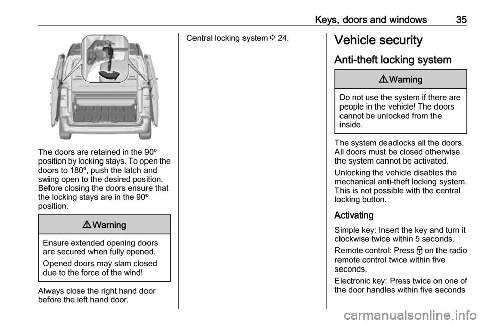
The doors are retained in the 90º
position by locking stays. To open the
doors to 180º, push the latch and
swing open to the desired position.
Before closing the doors ensure that
the locking stays are in the 90º
position.
9 Warning
Ensure extended opening doors
are secured when fully opened.
Opened doors may slam closed due to the force of the wind!
Always close the right hand doorbefore the left hand door.
Central locking system 3 24.Vehicle security
Anti-theft locking system9 Warning
Do not use the system if there are
people in the vehicle! The doorscannot be unlocked from the
inside.
The system deadlocks all the doors. All doors must be closed otherwise
the system cannot be activated.
Unlocking the vehicle disables the
mechanical anti-theft locking system.
This is not possible with the central
locking button.
Activating
Simple key: Insert the key and turn it
clockwise twice within 5 seconds.
Remote control: Press - on the radio
remote control twice within five seconds.
Electronic key: Press twice on one of
the door handles within five seconds
Page 84 of 289

82StorageSliding the flap
Slide the flap to the side. It is kept in
position by magnets.
Fitting the protective net
The protective net must be installed
whenever the bench seat of the front
passenger side is folded and the
partition flap is open.
1. Lift the seat cushion of the bench seat of the front passenger side.
Seat folding 3 50.
2. Fix the net like shown on the
picture.
3. Fit the attachment in the opening.
To lock the attachment turn it
clockwise a quarter turn.
4. Attach the hooks to the lashing eyes in the glovebox and on the
floor.
After transportation remove the
protective net and fold down the seat.
Second row bench seat in the
commercial vehicle
The bench seat in the second row can be folded to increase the load
compartment.
Page 86 of 289

84StorageInstallation in the roof frame
1.There are installation openings on
both sides in the roof frame. If
present, open the covers.
2. Suspend and engage the rod of net at one side, compress rod and
suspend and engage at the other
side.
Installation on the floor 1. a) Installation with lashing eyes
Attach the hooks of safety net
straps in the lashing eyes.
Lashing eyes 3 81.
b) Installation with rear seats on
rails
Insert the fixings in the floor
anchorages on both sides. To lock
the fixings turn them clockwise a
quarter turn. Place them as close as possible to the end of the rail.
c) Installation with fixed rear seats
Insert the fixings in the floor
anchorages on both sides.
Page 94 of 289

92Instruments and controlsInstruments and
controlsControls ....................................... 93
Steering wheel adjustment ........93
Steering wheel controls .............93
Horn ........................................... 94
Steering column controls ...........94
Windscreen wiper and washer ..94
Rear window wiper and washer ...................................... 96
Outside temperature ..................96
Clock ......................................... 97
Power outlets ............................. 97
Warning lights, gauges and indi‐
cators ......................................... 100
Instrument cluster ....................100
Speedometer ........................... 104
Odometer ................................ 105
Trip odometer .......................... 105
Tachometer ............................. 106
Fuel gauge .............................. 106
Engine coolant temperature gauge ..................................... 107
Engine oil level monitor ...........108
Service display ........................ 108
Control indicators ....................109Turn lights................................ 109
Seat belt reminder ...................109
Airbag and belt tensioners .......110
Airbag deactivation ..................110
Charging system .....................110
Malfunction indicator light ........110
Service vehicle soon ...............111
Stop engine ............................. 111
System check .......................... 111
Brake system ........................... 111
Parking brake .......................... 111
Antilock brake system (ABS) ...111
Gear shifting ............................ 112
Lane departure warning ..........112
Electronic Stability Control and Traction Control system .........112
Engine coolant temperature ....112
Preheating ............................... 112
Exhaust filter ............................ 112
AdBlue ..................................... 113
Deflation detection system ......113
Engine oil pressure ..................113
Low fuel ................................... 113
Autostop .................................. 114
Exterior light ............................ 114
Low beam ................................ 114
High beam ............................... 114
High beam assist .....................114
LED headlights ........................ 114
Front fog lights ......................... 114Rear fog light........................... 114
Rain sensor ............................. 114
Cruise control .......................... 114
Adaptive cruise control ............114
Vehicle detected ahead ...........114
Side blind spot alert .................115
Active emergency braking .......115
Speed limiter ........................... 115
Door open ................................ 115
Displays ..................................... 115
Driver Information Centre ........115
Info Display .............................. 119
Head-up display ......................120
Vehicle messages ......................122
Warning chimes .......................122
Vehicle personalisation ..............123
Telematics services ...................127
Vauxhall Connect ....................127
Page 99 of 289
Instruments and controls97Clock
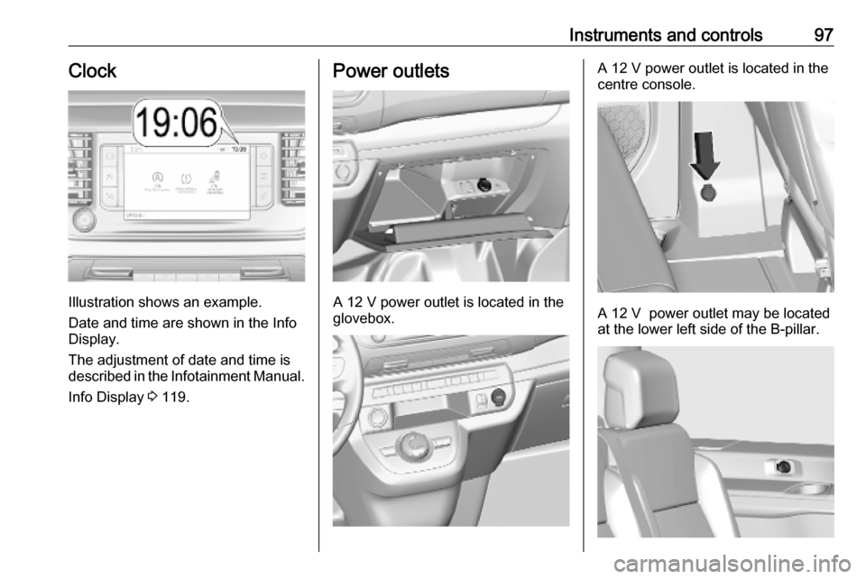
Illustration shows an example.
Date and time are shown in the Info
Display.
The adjustment of date and time is
described in the Infotainment Manual.
Info Display 3 119.
Power outlets
A 12 V power outlet is located in the
glovebox.
A 12 V power outlet is located in the
centre console.
A 12 V power outlet may be located
at the lower left side of the B-pillar.
Page 141 of 289
Climate control139Adjust the air flow by turning ý to the
desired speed.clockwise:increaseanticklockwise:decrease
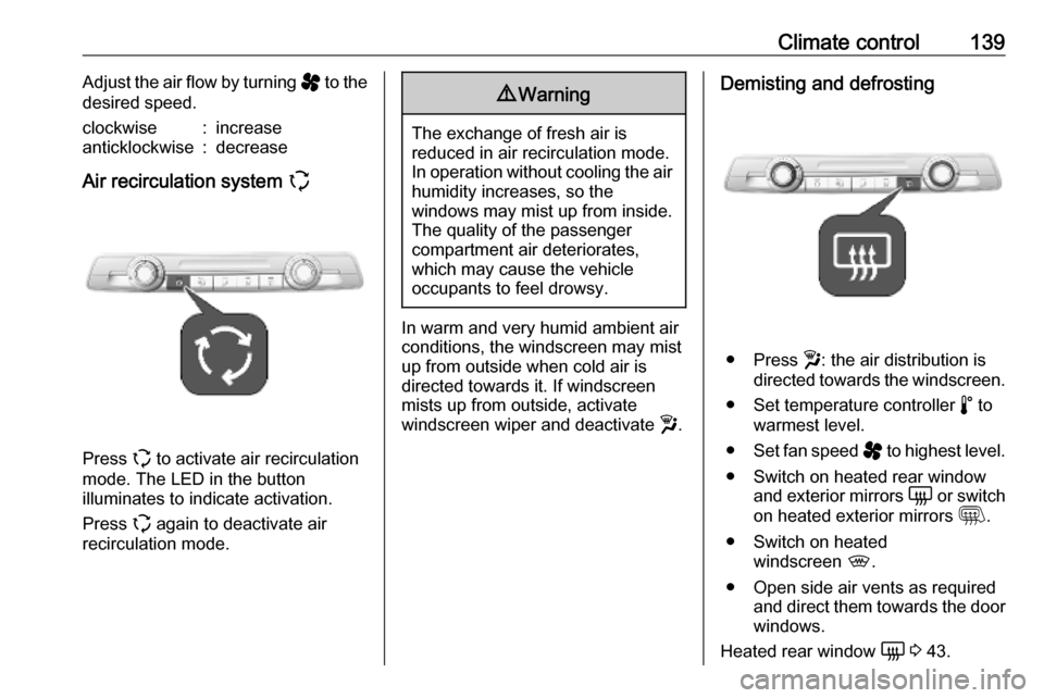
Air recirculation system q
Press q to activate air recirculation
mode. The LED in the button
illuminates to indicate activation.
Press q again to deactivate air
recirculation mode.
9 Warning
The exchange of fresh air is
reduced in air recirculation mode.
In operation without cooling the air humidity increases, so the
windows may mist up from inside.
The quality of the passenger
compartment air deteriorates,
which may cause the vehicle
occupants to feel drowsy.
In warm and very humid ambient air conditions, the windscreen may mist
up from outside when cold air is
directed towards it. If windscreen
mists up from outside, activate
windscreen wiper and deactivate w.
Demisting and defrosting
● Press w: the air distribution is
directed towards the windscreen.
● Set temperature controller ñ to
warmest level.
● Set fan speed ý to highest level.
● Switch on heated rear window and exterior mirrors è or switch
on heated exterior mirrors m.
● Switch on heated windscreen ,.
● Open side air vents as required and direct them towards the doorwindows.
Heated rear window è 3 43.
Page 142 of 289
140Climate controlHeated exterior mirrors m 3 39.
Heated windscreen 9 3 44.
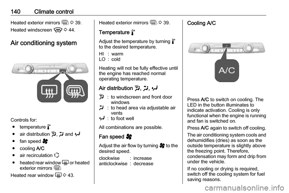
Air conditioning system
Controls for: ● temperature ñ
● air distribution w, x and y
● fan speed ý
● cooling A/C
● air recirculation q
● heated rear window è or heated
exterior mirrors m
Heated rear window è 3 43.
Heated exterior mirrors m 3 39.
Temperature ñ
Adjust the temperature by turning ñ
to the desired temperature.HI:warmLO:cold
Heating will not be fully effective until
the engine has reached normal
operating temperature.
Air distribution w, x , y
w:to windscreen and front door
windowsx:to head area via adjustable air
ventsy:to foot well
All combinations are possible.
Fan speed ý
Adjust the air flow by turning ý to the
desired speed.
clockwise:increaseanticlockwise:decreaseCooling A/C
Press A/C to switch on cooling. The
LED in the button illuminates to
indicate activation. Cooling is only
functional when the engine is running and fan is switched on.
Press A/C again to switch off cooling.
The air conditioning system cools and
dehumidifies (dries) as soon as the
outside temperature is slightly above
the freezing point. Therefore,
condensation may form and drip from
under the vehicle.
If no cooling or drying is required,
switch off the cooling system for fuel
saving reasons.
Page 166 of 289
164Driving and operating
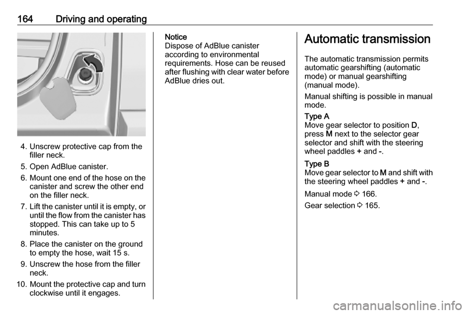
4. Unscrew protective cap from thefiller neck.
5. Open AdBlue canister.
6. Mount one end of the hose on the
canister and screw the other end
on the filler neck.
7. Lift the canister until it is empty, or
until the flow from the canister has stopped. This can take up to 5
minutes.
8. Place the canister on the ground to empty the hose, wait 15 s.
9. Unscrew the hose from the filler neck.
10. Mount the protective cap and turn
clockwise until it engages.
Notice
Dispose of AdBlue canister
according to environmental
requirements. Hose can be reused
after flushing with clear water before
AdBlue dries out.Automatic transmission
The automatic transmission permits
automatic gearshifting (automatic
mode) or manual gearshifting
(manual mode).
Manual shifting is possible in manual
mode.Type A
Move gear selector to position D,
press M next to the selector gear
selector and shift with the steering
wheel paddles + and -.Type B
Move gear selector to M and shift with
the steering wheel paddles + and -.
Manual mode 3 166.
Gear selection 3 165.
Page 206 of 289
204Driving and operatingArctic grade diesel fuel can be used
in extreme low temperatures below
-20 °C. Using this fuel grade in warm
or hot climates is not recommended
and may cause engine stalling, poor
starting or damage on the fuel
injection system.
Refuelling9 Danger
Before refuelling, switch off
ignition and any external heaters
with combustion chambers.
Follow the operating and safety
instructions of the filling station
when refuelling.
9 Danger
Fuel is flammable and explosive.
No smoking. No naked flames or
sparks.
If a smell of fuel can be noticed
inside the vehicle, have the cause of this remedied immediately by aworkshop.
A label with symbols at the fuel filler
flap is indicating the allowed fuel
types. In Europe the pump nozzles of the filling stations are marked with
these symbols. Refuel only the
allowed fuel type.Caution
In case of misfuelling, do not
switch on ignition.
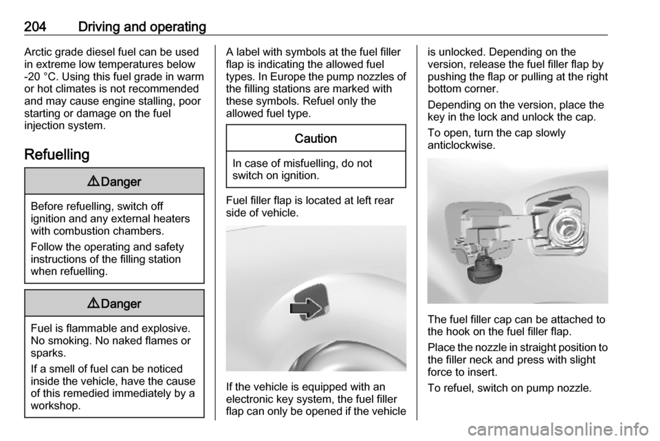
Fuel filler flap is located at left rear
side of vehicle.
If the vehicle is equipped with an
electronic key system, the fuel filler
flap can only be opened if the vehicle
is unlocked. Depending on the
version, release the fuel filler flap by
pushing the flap or pulling at the right bottom corner.
Depending on the version, place the
key in the lock and unlock the cap.
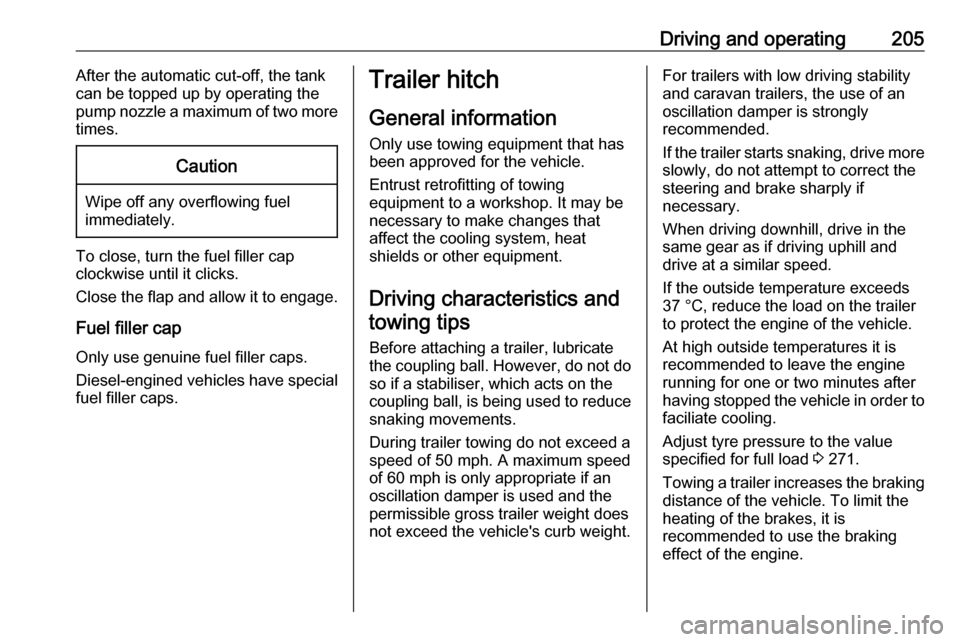
To open, turn the cap slowly
anticlockwise.
The fuel filler cap can be attached to
the hook on the fuel filler flap.
Place the nozzle in straight position to the filler neck and press with slight
force to insert.
To refuel, switch on pump nozzle.
Page 207 of 289
Driving and operating205After the automatic cut-off, the tank
can be topped up by operating the
pump nozzle a maximum of two more
times.Caution
Wipe off any overflowing fuel
immediately.
To close, turn the fuel filler cap
clockwise until it clicks.
Close the flap and allow it to engage.
Fuel filler cap
Only use genuine fuel filler caps.
Diesel-engined vehicles have special fuel filler caps.
Trailer hitch
General information
Only use towing equipment that has
been approved for the vehicle.
Entrust retrofitting of towing
equipment to a workshop. It may be
necessary to make changes that
affect the cooling system, heat
shields or other equipment.
Driving characteristics and towing tips
Before attaching a trailer, lubricate
the coupling ball. However, do not do so if a stabiliser, which acts on thecoupling ball, is being used to reduce
snaking movements.
During trailer towing do not exceed a
speed of 50 mph. A maximum speed
of 60 mph is only appropriate if an
oscillation damper is used and the
permissible gross trailer weight does
not exceed the vehicle's curb weight.For trailers with low driving stability
and caravan trailers, the use of an
oscillation damper is strongly
recommended.
If the trailer starts snaking, drive more slowly, do not attempt to correct the
steering and brake sharply if
necessary.
When driving downhill, drive in the
same gear as if driving uphill and
drive at a similar speed.
If the outside temperature exceeds
37 °C, reduce the load on the trailer
to protect the engine of the vehicle.
At high outside temperatures it is
recommended to leave the engine
running for one or two minutes after
having stopped the vehicle in order to
faciliate cooling.
Adjust tyre pressure to the value
specified for full load 3 271.
Towing a trailer increases the braking
distance of the vehicle. To limit the
heating of the brakes, it is
recommended to use the braking
effect of the engine.