ECU VAUXHALL ZAFIRA TOURER 2016 Owner's Guide
[x] Cancel search | Manufacturer: VAUXHALL, Model Year: 2016, Model line: ZAFIRA TOURER, Model: VAUXHALL ZAFIRA TOURER 2016Pages: 305, PDF Size: 9.15 MB
Page 139 of 305

Instruments and controls137Notice
The vehicle location always remains
accessible to OnStar in the case of
an emergency.
Find the privacy policy in your
account.
Software updates
OnStar may remotely carry out
software updates without further
notice or consent. These updates are
to enhance or maintain safety and
security or the operation of the
vehicle.
These updates may concern privacy
issues. Find the privacy policy in your account.
Page 172 of 305

170Driving and operatingWhen a gear is engaged, the vehicle
slowly begins to creep when the
brake is released.
Engine braking To utilise the engine braking effect,
select a lower gear in good time when
driving downhill, see manual mode.
Rocking the vehicle Rocking the vehicle is only
permissible if the vehicle is stuck in
sand, mud or snow. Move the selector
lever between D and R in a repeat
pattern. Do not race the engine and
avoid sudden acceleration.
Parking Apply the parking brake and engageP .
The ignition key can only be removed
when the selector lever is in position
P .Manual mode
Move selector lever out of position D
towards the left and then forwards or backwards.
<:shift to a higher gear]:shift to a lower gear
If a higher gear is selected when
vehicle speed is too low, or a lower
gear when vehicle speed is too high,
the shift is not executed. This can
cause a message in the Info-Display.
In manual mode no automatic shifting
to a higher gear takes place at high
engine revolutions.
Electronic driving
programmes
● Following a cold start, the operating temperature
programme increases engine
speed to quickly bring the
catalytic converter to the required
temperature.
● The automatic neutral shift function automatically shifts gear
to idling when the vehicle is
stopped with a forward gear
engaged and the brake pedal is
pressed.
● When SPORT mode is engaged,
the vehicle shifts at higher engine
speeds (unless cruise control is
on). SPORT mode 3 177.
● Special programmes automatically adapt the gearshift
points when driving up inclines or down hills.
● When starting-off in snowy or icy conditions or on other slippery
surfaces, the electronic
transmission control selects a
higher gear automatically.
Page 221 of 305

Driving and operating219Rear axle loadWhen the trailer is coupled and the
towing vehicle fully loaded, the
permissible rear axle load (see
identification plate or vehicle
documents) may be exceeded by
60 kg , the gross vehicle weight rating
may be exceeded by 60 kg. If the
permissible rear axle load is
exceeded, a maximum speed of
60 mph applies.
Towing equipmentCaution
When operating without a trailer,
remove the coupling ball bar.
Stowage of coupling ball bar
The bag with the coupling ball bar is
stowed in the load compartment.
Place the strap through the right rear lashing eye, wrap around twice and
tighten the strap to secure the bag.
Fitting the coupling ball bar
Disengage and fold down the socket. Remove the sealing plug from the
opening for the coupling ball bar and
stow it.
Page 234 of 305
232Vehicle care
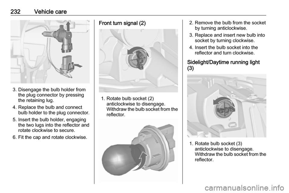
3. Disengage the bulb holder fromthe plug connector by pressing
the retaining lug.
4. Replace the bulb and connect bulb holder to the plug connector.
5. Insert the bulb holder, engaging the two lugs into the reflector and
rotate clockwise to secure.
6. Fit the cap and rotate clockwise.
Front turn signal (2)
1. Rotate bulb socket (2) anticlockwise to disengage.
Withdraw the bulb socket from the
reflector.
2. Remove the bulb from the socket by turning anticlockwise.
3. Replace and insert new bulb into socket by turning clockwise.
4. Insert the bulb socket into the reflector and turn clockwise.
Sidelight/Daytime running light
(3)
1. Rotate bulb socket (3) anticlockwise to disengage.
Withdraw the bulb socket from the
reflector.
Page 236 of 305
234Vehicle care
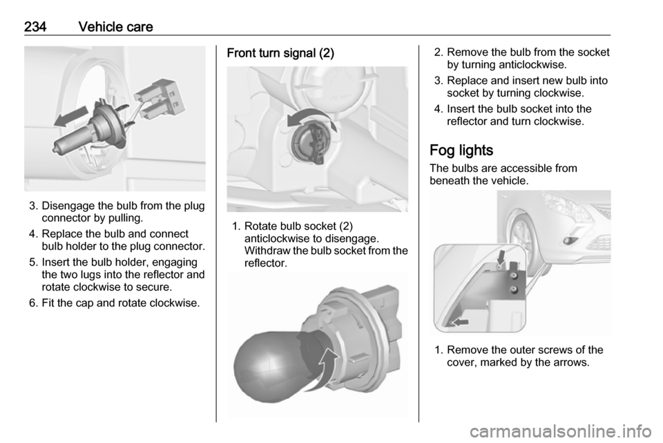
3. Disengage the bulb from the plugconnector by pulling.
4. Replace the bulb and connect bulb holder to the plug connector.
5. Insert the bulb holder, engaging the two lugs into the reflector and
rotate clockwise to secure.
6. Fit the cap and rotate clockwise.
Front turn signal (2)
1. Rotate bulb socket (2) anticlockwise to disengage.
Withdraw the bulb socket from the
reflector.
2. Remove the bulb from the socket by turning anticlockwise.
3. Replace and insert new bulb into socket by turning clockwise.
4. Insert the bulb socket into the reflector and turn clockwise.
Fog lights
The bulbs are accessible from
beneath the vehicle.
1. Remove the outer screws of the cover, marked by the arrows.
Page 257 of 305

Vehicle care255Make the following preparations and
observe the following information:
● Park the vehicle on a level, firm and non-skid surface. The front
wheels must be in the straight- ahead position.
● Apply the parking brake and engage first gear, reverse gear or
P .
● Remove the spare wheel 3 257.
● Never change more than one wheel at once.
● Use the jack only to change wheels in case of puncture, not
for seasonal winter or summer
tyre change.
● The jack is maintenance-free. ● If the ground on which the vehicle
is standing is soft, a solid board
(max. 1 cm thick) should be
placed under the jack.
● Take heavy objects out of the vehicle before jacking up.
● No people or animals may be in the vehicle when it is jacked-up.
● Never crawl under a jacked-up vehicle.●Do not start the vehicle when it is
raised on the jack.
● Clean wheel nuts and thread with
a clean cloth before mounting the wheel.9 Warning
Do not grease wheel bolt, wheel
nut and wheel nut cone.
1. Disengage wheel nut caps with a
screwdriver and remove. Pull off
the wheel cover. Vehicle tools
3 245.
Alloy wheels: Disengage wheel
nut caps with a screwdriver and
remove. To protect the wheel,
place a soft cloth between the
screwdriver and the alloy wheel.
2. Fold out the wheel wrench and install ensuring that it locates
securely and loosen each wheel
nut by half a turn.
The wheels might be protected by
locking wheel nuts. To loosen
these specific nuts first attach the
adapter onto the head of the nut
before installing the wheel
wrench. The adapter is located in
the glovebox.
Page 258 of 305

256Vehicle care
3.Some versions may have covered
the vehicle jacking point. Pull out
the cover sideways.
4. Ensure the jack is correctly positioned under the relevant
vehicle jacking point.
5. Set the jack to the necessary height. Position it directly below
the jacking point in a manner that
prevents it from slipping.
Attach wheel wrench and with the
jack correctly aligned rotate wheel wrench until wheel is clear of the
ground.
6. Unscrew the wheel nuts. 7. Change the wheel. Spare wheel 3 257
8. Screw on the wheel nuts.
9. Lower vehicle.
10. Install the wheel wrench ensuring that it locates securely and tighten
each nut in a crosswise
sequence. Tightening torque is
140 Nm.
Page 260 of 305
258Vehicle care
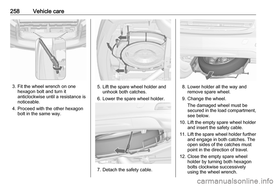
3. Fit the wheel wrench on onehexagon bolt and turn it
anticlockwise until a resistance is
noticeable.
4. Proceed with the other hexagon bolt in the same way.5. Lift the spare wheel holder andunhook both catches.
6. Lower the spare wheel holder.
7. Detach the safety cable.
8. Lower holder all the way and remove spare wheel.
9. Change the wheel. The damaged wheel must be
secured in the load compartment,
see below.
10. Lift the empty spare wheel holder and insert the safety cable.
11. Lift the spare wheel holder further
and engage in both catches. The open sides of the catches must
point in the direction of travel.
12. Close the empty spare wheel holder by turning both hexagon
bolts clockwise successively using the wheel wrench.
Page 261 of 305

Vehicle care25913. Fit the caps above both hexagonbolts.
14. Stow wheel wrench and the jack in the stowage in front of the
tailgate.
15. Close the stowage compartment cover.
When stowing the spare wheel in the
spare wheel holder, note that the
wheel is positioned with the tyre valve
above the recess of the wheel holder.
Stowing a damaged wheel in the
load compartment
The spare wheel holder is not
designed for other tyre sizes than the
spare wheel.
A damaged wheel wider than the
spare wheel must be stowed in the
load compartment and secured with a strap. Vehicle tools 3 245.
The seats of the third row must be folded down 3 79.
1. Position the wheel close to the left
sidewall of the load compartment.
2. Place the loop end of the strap through the front lashing eye on
the left side.
3. Place the hook end of the strap through the loop and pull it until
the strap is fastened securely to
the lashing eye.4. Insert the strap through the spokes of the wheel as shown in
the illustration.
5. Mount the hook to the rear left lashing eye.
6. Tighten the strap and secure it using the buckle.
9 Danger
Always drive with folded up and
engaged rear seat backrests when stowing a damaged full size wheel
in the load compartment.
Page 262 of 305

260Vehicle care9Warning
Storing a jack, a wheel or other
equipment in the load
compartment could cause injury if they are not fixed properly. During a sudden stop or a collision, looseequipment could strike someone.
Always store jack and tools in the
respective storage compartments
and secure them by fixing.
Damaged wheel placed in the load
compartment must always be
secured by the strap.
Temporary spare wheel
The use of the temporary spare wheel could affect driveability. Have the
defective tyre renewed or repaired as
soon as possible.
Only mount one temporary spare
wheel. Do not drive faster than
50 mph. Take curves slowly. Do not
use for a long period of time.
If your vehicle gets a flat tyre on the
rear while towing another vehicle,
mount the temporary spare wheel in
the front and the full tyre in the rear.
Tyre chains 3 251.
Spare wheel with directional tyre Fit directional tyres such that they rollin the direction of travel. The rolling
direction is indicated by a symbol
(e.g. an arrow) on the sidewall.
The following applies to tyres fitted
opposing the rolling direction:
● Driveability may be affected. Have the defective tyre renewed
or repaired as soon as possible.
● Drive particularly carefully on wet
and snow-covered road
surfaces.Jump starting
Do not start with quick charger.
A vehicle with a discharged battery
can be started using jump leads and
the battery of another vehicle.9 Warning
Be extremely careful when starting
with jump leads. Any deviation
from the following instructions can
lead to injuries or damage caused
by battery explosion or damage to the electrical systems of both
vehicles.
9 Warning
Avoid contact of the battery with
eyes, skin, fabrics and painted
surfaces. The fluid contains
sulphuric acid which can cause
injuries and damage in the event
of direct contact.
● Never expose the battery to naked flames or sparks.