Button VAUXHALL ZAFIRA TOURER 2017 Service Manual
[x] Cancel search | Manufacturer: VAUXHALL, Model Year: 2017, Model line: ZAFIRA TOURER, Model: VAUXHALL ZAFIRA TOURER 2017Pages: 289, PDF Size: 8.91 MB
Page 190 of 289
188Driving and operatingDepending on which side of the
vehicle is closer to an obstacle, you will hear acoustic warning signals on
the respective side of the vehicle. The
interval between the sounds
becomes shorter as the vehicle gets
closer to that obstacle. When the
distance is less than approx. 30 cm,
the sound is continuous.
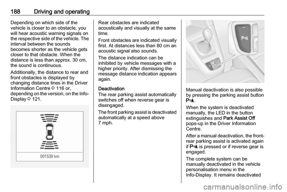
Additionally, the distance to rear and
front obstacles is displayed by
changing distance lines in the Driver
Information Centre 3 116 or,
depending on the version, on the Info- Display 3 121.Rear obstacles are indicated
acoustically and visually at the same
time.
Front obstacles are indicated visually
first. At distances less than 80 cm an
acoustic signal also sounds.
The distance indication can be
inhibited by vehicle messages with a higher priority. After dismissing themessage distance indication appears again.
Deactivation
The rear parking assist automatically
switches off when reverse gear is
disengaged.
The front parking assist is deactivated
automatically at a speed above
7 mph.
Manual deactivation is also possible by pressing the parking assist button
r .
When the system is deactivated
manually, the LED in the button
extinguishes and Park Assist Off
pops-up in the Driver Information
Centre.
After a manual deactivation, the front- rear parking assist is activated again
if r is pressed or if reverse gear is
engaged.
The complete system can be
manually deactivated in the vehicle
personalisation menu in the
Info-Display. It remains deactivated
Page 194 of 289
192Driving and operatingDue to the high position of the
camera, the rear bumper can be seen on the display as a guide to position.
The area displayed by the camera is
limited. The distance of the image that
appears on the display differs from
the actual distance.
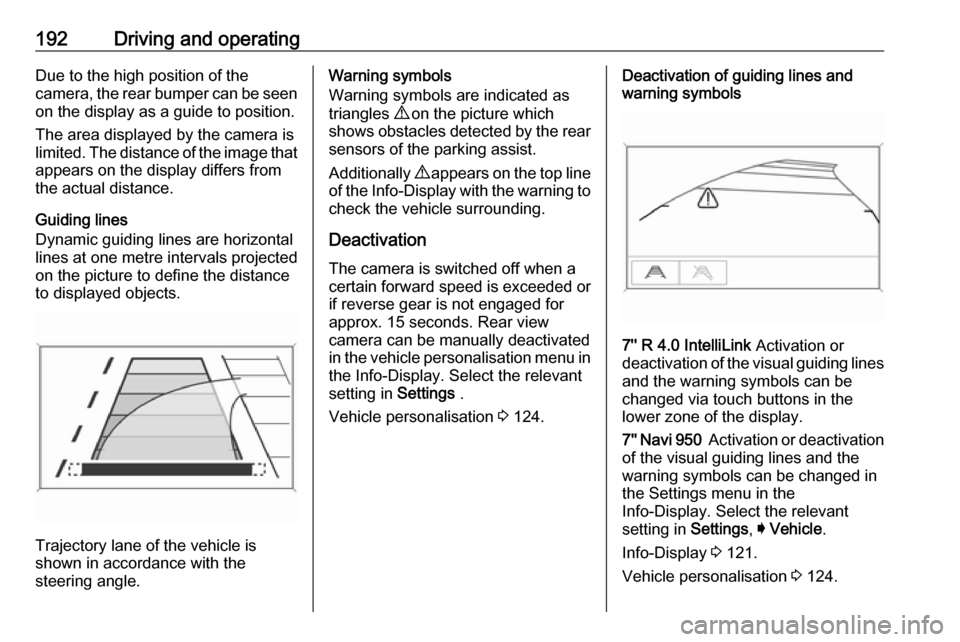
Guiding lines
Dynamic guiding lines are horizontal
lines at one metre intervals projected
on the picture to define the distance
to displayed objects.
Trajectory lane of the vehicle is
shown in accordance with the
steering angle.
Warning symbols
Warning symbols are indicated as
triangles 9 on the picture which
shows obstacles detected by the rear
sensors of the parking assist.
Additionally 9 appears on the top line
of the Info-Display with the warning to
check the vehicle surrounding.
Deactivation
The camera is switched off when a
certain forward speed is exceeded or
if reverse gear is not engaged for
approx. 15 seconds. Rear view
camera can be manually deactivated
in the vehicle personalisation menu in the Info-Display. Select the relevant
setting in Settings .
Vehicle personalisation 3 124.Deactivation of guiding lines and
warning symbols
7'' R 4.0 IntelliLink Activation or
deactivation of the visual guiding lines and the warning symbols can be
changed via touch buttons in the
lower zone of the display.
7'' Navi 950 Activation or deactivation
of the visual guiding lines and the
warning symbols can be changed in
the Settings menu in the
Info-Display. Select the relevant
setting in Settings, I Vehicle .
Info-Display 3 121.
Vehicle personalisation 3 124.
Page 199 of 289
Driving and operating197The lane departure warning system is
activated by pressing ). The
illuminated LED in the button
indicates that the system is switched
on. When the control indicator ) in
the instrument cluster illuminates
green, the system is ready to operate.
The system is only operable at
vehicle speeds above 35 mph and if
lane markings are available.
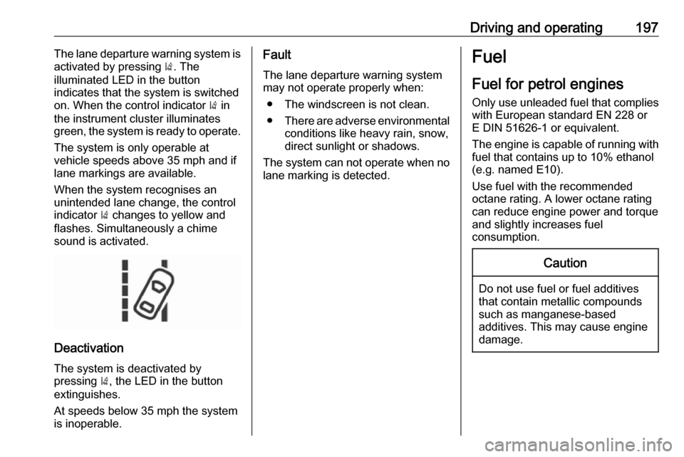
When the system recognises an
unintended lane change, the control
indicator ) changes to yellow and
flashes. Simultaneously a chime
sound is activated.
Deactivation
The system is deactivated by
pressing ), the LED in the button
extinguishes.
At speeds below 35 mph the system
is inoperable.
Fault
The lane departure warning system may not operate properly when:
● The windscreen is not clean.
● There are adverse environmental
conditions like heavy rain, snow,
direct sunlight or shadows.
The system can not operate when no
lane marking is detected.Fuel
Fuel for petrol engines Only use unleaded fuel that complies
with European standard EN 228 or
E DIN 51626-1 or equivalent.
The engine is capable of running with
fuel that contains up to 10% ethanol
(e.g. named E10).
Use fuel with the recommended
octane rating. A lower octane rating
can reduce engine power and torque
and slightly increases fuel
consumption.Caution
Do not use fuel or fuel additives
that contain metallic compounds
such as manganese-based
additives. This may cause engine
damage.
Page 207 of 289
Driving and operating205Press the button at the liquid gas
supply point. The filling system stops
or begins to run slowly when 80% of
the tank volume is reached
(maximum fill level).
Release button on filling system to stop the filling process. Release the
locking lever and remove the filler
nozzle. A small quantity of liquid gas
may escape.
Remove adapter and stow in vehicle.
Fit protective cap to prevent the
penetration of foreign bodies into the
filler opening and the system.9 Warning
Due to the system design, an
escape of liquid gas after
releasing the locking lever is
unavoidable. Avoid inhaling.
9 Warning
The liquid gas tank should only be
filled to 80% capacity, for safety
reasons.
The multivalve on the liquid gas tank
automatically limits the fill quantity. If
a larger quantity is added, we
recommend not exposing the vehicle
to the sun until the excess amount
has been used up.
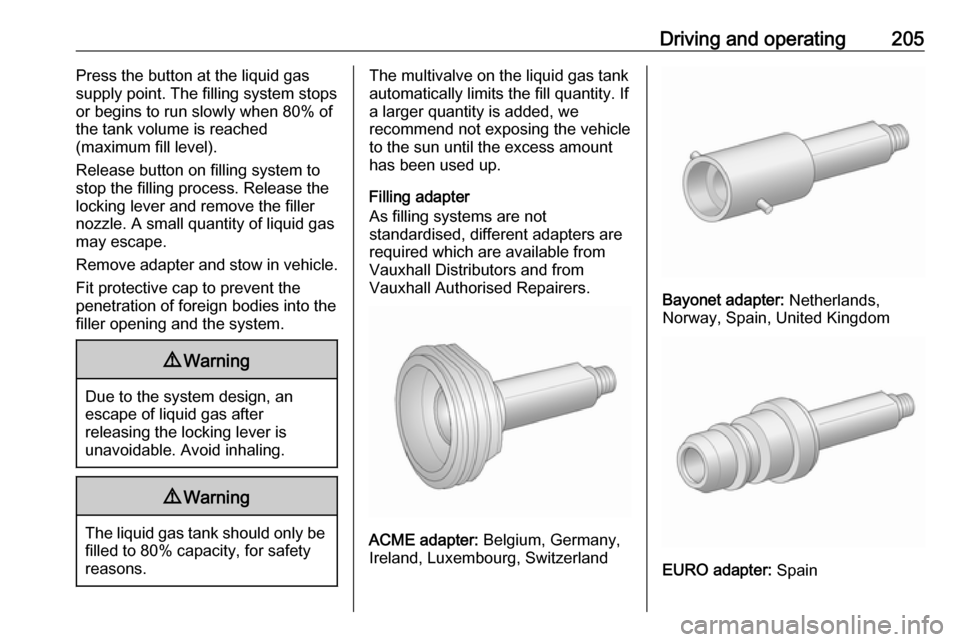
Filling adapter
As filling systems are not
standardised, different adapters are
required which are available from
Vauxhall Distributors and from
Vauxhall Authorised Repairers.
ACME adapter: Belgium, Germany,
Ireland, Luxembourg, Switzerland
Bayonet adapter: Netherlands,
Norway, Spain, United Kingdom
EURO adapter: Spain
Page 222 of 289
220Vehicle careMeaning of symbols:● No sparks, naked flames or smoking.
● Always shield eyes. Explosive gases can cause blindness or
injury.
● Keep the vehicle battery out of reach of children.
● The vehicle battery contains sulphuric acid which could cause
blindness or serious burn
injuries.
● See the Owner's Manual for further information.
● Explosive gas may be present in the vicinity of the vehicle battery.
Diesel fuel system bleeding
If the tank has been run dry, the diesel
fuel system must be bled. Switch on
the ignition three times for
15 seconds at a time. Then crank the
engine for a maximum of
40 seconds. Repeat this process after
no less than five seconds. If the
engine fails to start, seek the
assistance of a workshop.Wiper blade replacement
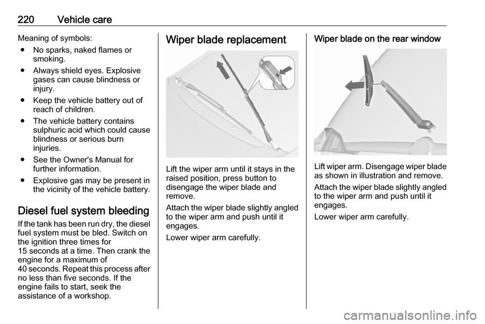
Lift the wiper arm until it stays in the
raised position, press button to
disengage the wiper blade and
remove.
Attach the wiper blade slightly angled
to the wiper arm and push until it
engages.
Lower wiper arm carefully.
Wiper blade on the rear window
Lift wiper arm. Disengage wiper blade as shown in illustration and remove.
Attach the wiper blade slightly angled
to the wiper arm and push until it
engages.
Lower wiper arm carefully.
Page 239 of 289
Vehicle care237Tyre pressure monitoringsystem
The tyre pressure monitoring system checks the pressure of all four tyres
once a minute when vehicle speed
exceeds a certain limit.Caution
Tyre pressure monitoring system
warns only about low tyre pressure condition and does not replace
regular tyre maintenance by the
driver.
All wheels must be equipped with pressure sensors and the tyres must
have the prescribed pressure.
Notice
In countries where the tyre pressure
monitoring system is legally
required, the use of wheels without
pressure sensors will invalidate the
vehicle type approval.
The current tyre pressures can be
shown in the Driver Information
Centre.
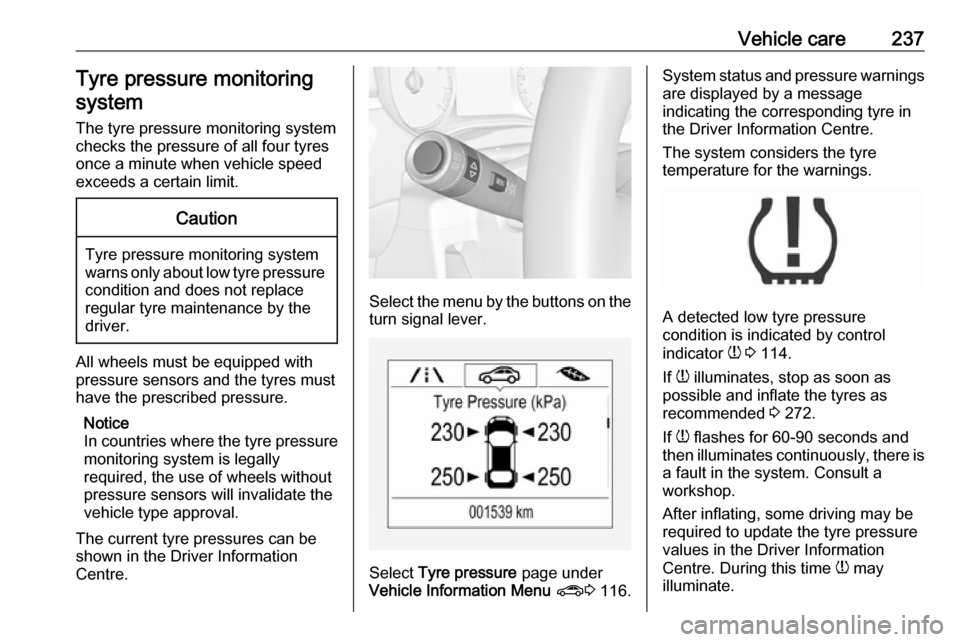
Select the menu by the buttons on the turn signal lever.
Select Tyre pressure page under
Vehicle Information Menu ? 3 116.
System status and pressure warnings
are displayed by a message
indicating the corresponding tyre in
the Driver Information Centre.
The system considers the tyre
temperature for the warnings.
A detected low tyre pressure
condition is indicated by control
indicator w 3 114.
If w illuminates, stop as soon as
possible and inflate the tyres as
recommended 3 272.
If w flashes for 60-90 seconds and
then illuminates continuously, there is
a fault in the system. Consult a
workshop.
After inflating, some driving may be
required to update the tyre pressure
values in the Driver Information
Centre. During this time w may
illuminate.
Page 241 of 289
Vehicle care239the wheels or exchanging the
complete wheel set and if one or more
tyre pressure sensors were replaced. The tyre pressure sensor matching
process should also be performed
after replacing a spare wheel with a
road wheel containing the tyre
pressure sensor.
The malfunction light w and the
warning message or code should
extinguish at the next ignition cycle. The sensors are matched to the
wheel positions, using a relearn tool,
in the following order: left side front
wheel, right side front wheel, right
side rear wheel and left side rear
wheel. The turn signal light at the
current active position is illuminated
until sensor is matched.
Consult your workshop for service.
There are two minutes to match the
first wheel position, and five minutes
overall to match all four wheel
positions. If it takes longer, the
matching process stops and must be
restarted.
The tyre pressure sensor matching
process is:
1. Apply the parking brake.2. Turn the ignition on.
3. On vehicles with automatic transmission: set the selector
lever to P.
On vehicles with manual
transmission: select neutral.
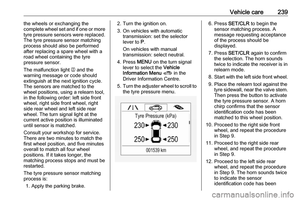
4. Press MENU on the turn signal
lever to select the Vehicle
Information Menu ? in the
Driver Information Centre.
5. Turn the adjuster wheel to scroll to
the tyre pressure menu.6. Press SET/CLR to begin the
sensor matching process. A
message requesting acceptance
of the process should be
displayed.
7. Press SET/CLR again to confirm
the selection. The horn sounds
twice to indicate the receiver is in
relearn mode.
8. Start with the left side front wheel.
9. Place the relearn tool against the tyre sidewall, near the valve stem.Then press the button to activate
the tyre pressure sensor. A horn
chirp confirms that the sensor
identification code has been
matched to this wheel position.
10. Proceed to the right side front wheel, and repeat the procedure
in Step 9.
11. Proceed to the right side rear wheel, and repeat the procedure
in Step 9.
12. Proceed to the left side rear wheel, and repeat the procedure
in Step 9. The horn sounds twice
to indicate the sensor
identification code has been
Page 245 of 289
Vehicle care24313. The prescribed tyre pressureshould be obtained within ten
minutes. Tyre pressure 3 272.
When the correct pressure is
obtained, switch off the
compressor.
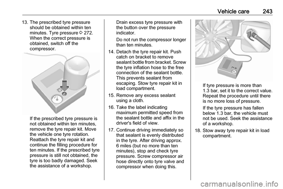
If the prescribed tyre pressure is
not obtained within ten minutes,
remove the tyre repair kit. Move
the vehicle one tyre rotation.
Reattach the tyre repair kit and
continue the filling procedure for
ten minutes. If the prescribed tyre
pressure is still not obtained, the
tyre is too badly damaged. Seek
the assistance of a workshop.
Drain excess tyre pressure with
the button over the pressure indicator.
Do not run the compressor longer
than ten minutes.
14. Detach the tyre repair kit. Push catch on bracket to remove
sealant bottle from bracket. Screw the tyre inflation hose to the free
connection of the sealant bottle.
This prevents sealant from
escaping. Stow tyre repair kit in
load compartment.
15. Remove any excess sealant using a cloth.
16. Take the label indicating maximum permitted speed from
the sealant bottle and affix in the
driver's field of view.
17. Continue driving immediately so that sealant is evenly distributed
in the tyre. After driving approx.
6 miles (but no more than ten
minutes), stop and check tyre
pressure. Screw compressor air
hose directly onto tyre valve and
compressor when doing this.
If tyre pressure is more than
1.3 bar , set it to the correct value.
Repeat the procedure until there
is no more loss of pressure.
If the tyre pressure has fallen
below 1.3 bar, the vehicle must
not be used. Seek the assistance
of a workshop.
18. Stow away tyre repair kit in load compartment.