VOLKSWAGEN CARAVELLE 1992 T4 / 4.G Owners Manual
Manufacturer: VOLKSWAGEN, Model Year: 1992, Model line: CARAVELLE, Model: VOLKSWAGEN CARAVELLE 1992 T4 / 4.GPages: 164, PDF Size: 25 MB
Page 131 of 164
Downloaded from www.Manualslib.com manuals search engine
DO-IT-YOURSELF
Masking
headlights
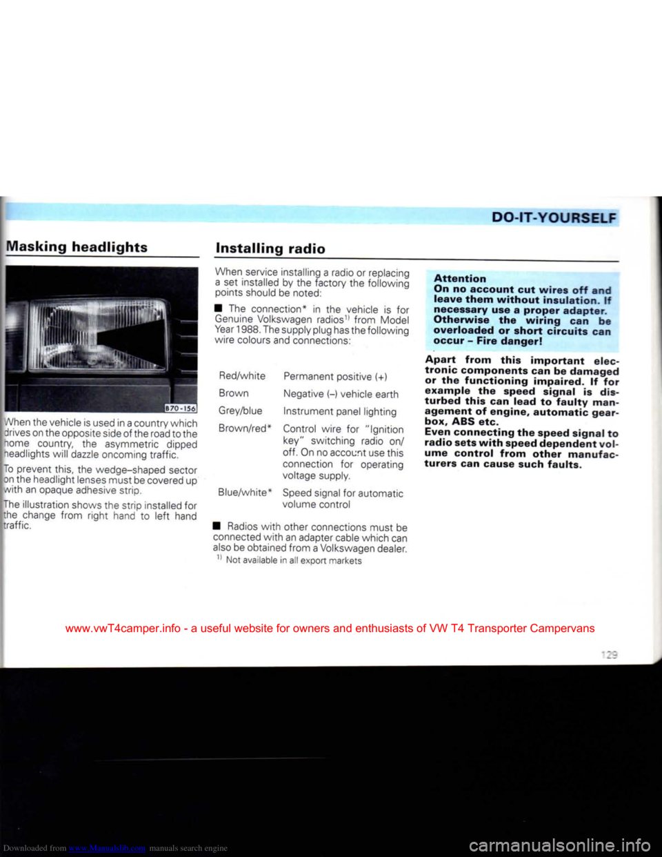
When the vehicle is used in a country which drives on the opposite side
of
the road to the
home country,
the
asymmetric dipped neadlights
will
dazzle oncoming
traffic.
To prevent this,
the
wedge-shaped sector on the headlight lenses must be covered
up
with
an
opaque adhesive strip.
The illustration shows
the
strip installed
for
the change
from
right
hand
to
left
hand
traffic.
Installing
radio
When service installing
a
radio
or
replacing
a
set
installed
by the
factory
the
following points should
be
noted:
•
The
connection*
in the
vehicle
is for
Genuine
Volkswagen radios11
from
Model
Year
1988. The supply plug has the following
wire colours and connections:
Red/white Permanent positive
(+)
Brown Negative
(-)
vehicle earth
Grey/blue
Instrument
panel lighting
Brown/red* Control wire
for
"Ignition
key" switching radio
on/
off. On no account use this
connection
for
operating
voltage supply.
Blue/white*
Speed
signal
for
automatic volume control
•
Radios
with
other connections must
be
connected
with
an adapter cable which can
also
be obtained
from
a Volkswagen dealer.
11 Not available
in all
export markets
Attention
On
no account cut wires off and
leave
them
without
insulation. If
necessary
use a proper adapter.
Otherwise the wiring can be
overloaded or short circuits can
occur
- Fire danger!
Apart from this important elec
tronic components can be damaged or the functioning impaired. If for
example the speed signal is
dis
turbed this can lead to
faulty
man agement of engine, automatic gearbox, ABS etc.
Even
connecting the speed signal to
radio sets
with
speed dependent
vol
ume control from other manufac
turers can cause
such
faults.
www.vwT4camper.info - a useful website for owners and enthusiasts of VW T4 Transporter Campervans
Page 132 of 164
Downloaded from www.Manualslib.com manuals search engine
DO-IT-YOURSELF
• The radios from the Genuine Volks wagen Accessory Programme11 are similar
to those used in the factory and ensure
trouble-free installation. These sets are in keeping
with
the advanced technology and
well-planned easy-to-operate design. In
Germany
there is also an Exchange Service
for these radios so
that
even after years of
use
a set requiring repair can be exchanged
cheaply
for a completely reconditioned,
good-as-new
set by a Volkswagen dealer.
• Loudspeakers,
fitting
parts, aerials and
suppression
kits should also be taken from
the Genuine Volkswagen Accessory
Pro
gramme11. These parts have all been
specially
developed for each vehicle model. • When installing the aerial it is essential to
ensure
that
the hole provided by the factory
where the aerial enters the body is sealed
very carefully. In addition the aerial cable,
the connecting wires and the loudspeaker
wires must be routed so
that
they cannot
chafe,
rattle
or get tangled up
with
moving parts (e.g. pedals, steering, heating controls
etc.). Otherwise the operation of the
con
trols may be affected or vehicle safety im
paired.
In
cases
of doubt, exact information can be
obtained from Volkswagen dealers.
Emergency
starting
|B43-
174[
A
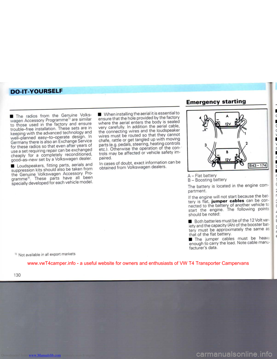
- Flat battery
B
- Boosting battery
The battery is located in the engine com partment.
If the engine will not start because the ba:-
tery is
flat,
jumper
cables can be
con
nected to the battery of another vehicle tc
start the engine. The following points
should be noted:
• Both batteries must be of the 12 Volt var iety and the capacity (Ah) of the booster bat
tery must be approximately the same as
that
of the
flat
battery.
• The jumper cables must be heav enough to carry the load. Note cable manu
facturer's data.
Not available in all export markets
130
www.vwT4camper.info - a useful website for owners and enthusiasts of VW T4 Transporter Campervans
Page 133 of 164
Downloaded from www.Manualslib.com manuals search engine
DO-IT-YOURSELF
• Only
use
jumper cables
with
insulated
clips.
•
A
flat
battery can freeze
at
-10 degrees
C
and
if
a battery is frozen
it
must be thawed
out before connecting jumper
cables,
other
wise
it
could explode.
• There must
be no
contact between
the
vehicles,
otherwise current
can
flow
as
soon
as
the
plus terminals are connected.
•
The
flat
battery must
be
properly
con
nected
to the
electrical system.
• The engine
of
the boosting vehicle must be running.
•
The
jumper cables must only
be
con
nected as follows:
1. One end
of (+)
cable (usually red)
to the
(+)
terminal
of
the
flat
battery.
2.
Other end
of
the red cable
to the (+)
ter
minal
of
boosting battery.
3.
One end
of (-)
cable (usually black)
to the (-)
terminal
of
boosting battery.
4.
Other
end of
black cable
(X) to a
solid metal part bolted
to
the block
or to
cylinder
block itself.
Do
not
connect the cable
to
the
flat
battery
minus terminal. The sparks could ignite
the
explosive
gas flowing
out of the
battery.
Attention
•
The non-insulated parts of the
cable clips must not touch one
another on any account. Further more the jumper cable attached
to the
battery
positive terminal must not come into contact
with
electrically conductive vehicle parts - Short circuit danger!
•
Route the jumper cables so
that
they cannot come into
con
tact
with
rotating parts in the en gine compartment.
•
Do not stand
with
your face
over the
battery
- danger of acid
burns!
•
Keep sources of ignition (naked flames, burning
ciga
rettes
etc.)
well
away from the
battery
- Explosion danger!
• Start
the
engine
as
described
in the
"Starting engine" section.
•
If
the engine does not start
at
once, stop using starter after
10
seconds, wait about
half
a
minute and then
try
again.
• With engine running, disconnect cables in reverse sequence.
-.3'
www.vwT4camper.info - a useful website for owners and enthusiasts of VW T4 Transporter Campervans
Page 134 of 164
Downloaded from www.Manualslib.com manuals search engine
DO-IT-YOURSELF
Tow
starting/towing
General
notes
• "owing eyes are provided on the
right
under
front
and rear bumpers.
Tow-ropes
or bars should be attached at
these
points only.
On
vehicles
with
a factory
fitted
towing bracket a towing eye is not fitted. On those
vehicles
the towing bracket can be used for
towing.
• The tow-rope should be slightly elastic to reduce the risk of damage to both ve
hicles.
It is advisable to use synthetic fibre
ropes,
or ropes of similar elastic material. It
is
however
safer
to use a
tow-bar!
Avoid
excessive towing
effort
and do not
jerk.
During towing operations on other than
surfaced
roads there is always the danger
that
the attachment points will be over
loaded
and damaged.
•
Before
trying
to
start
engine
by
towing,
the
battery
from
another
ve
hicle
should be used for
starting
if
possible - see previous page. If the
vehicle
has to be tow
started
or
towed
at any
time,
the
following
must
be noted:
•
Check
whether there are any local traffic regulations concerning the towing of ve
hicles.
• Both drivers must be familiar
with
tow ing procedures. Inexperienced drivers
should
not attempt to tow start or tow.
• When using a tow-rope the driver of the towing vehicle must engage the clutch very gently when moving off and changing gear.
• The driver of the vehicle being towed must ensure
that
the tow-rope is always
taut.
• The emergency lights must be switchec
on on both vehicles - unless local regula
tions differ.
• Turn ignition key to "Drive" position sc
that
the steering wheel is free and the
turr
signals,
horn, and, if necessary, the wind
screen
wiper and washer can be
used.
• As the brake servo only works when the engine is running, considerably more pres
sure
is required on the brake pedal when the
engine is not running.
• On vehicles
with
power assisted steer ing more force is required to
turn
steering
wheel when engine is not running.
• When there is no lubricant in the manua or automatic gearbox, the vehicle may only
be
towed
with
driving wheels lifted.
132
www.vwT4camper.info - a useful website for owners and enthusiasts of VW T4 Transporter Campervans
Page 135 of 164
Downloaded from www.Manualslib.com manuals search engine
DO-IT-YOURSELF
Tow
starting
The
following
points
must
be
noted
when
tow
starting:
•
Before
moving off, engage 2nd or 3rd gear.
• Switch ignition on.
• As soon as engine starts, depress clutch and move gear lever
into
neutral to avoid running
into
the towing vehicle.
• On
vehicles
with
a
catalytic
con
verter
the
engine
must
not be
started
by
towing
the
vehicle
in ex
cess of 50 m1. Because
then,
un-
burnt
fuel
can pass
into
the con
verter
and cause
damage.
• For
technical
reasons tow
start
ing a
vehicle
with
an
automatic
gearbox
is not possible.
Towing
When
towing
vehicles
with
an
auto
matic
gearbox,
the following points must be noted in addition to the details on
the previous page:
• Selector lever at "N".
• Do not have the vehicle towed faster than 30 mph (50 km/h).
• To not tow
further
than 30 miles (50 kilo meters). If the vehicle has to be towed long distances
it must be
lifted
at the
front.
Reason:
When the engine is not running,
the gearbox oil pump is not working and the
gearbox is not adequately lubricated for high speeds or long distances.
• With a breakdown vehicle the vehicle may only be suspended at the
front.
Reason:
If given a rear suspended tow, the
drive shafts
turn
backwards. The planetary
gears
in the automatic gearbox then
turn
at
such
high speeds
that
the gearbox will be
severely
damaged in a short time.
Does
not apply to 50 kW Diesel engine
with
catalytic converter
133
www.vwT4camper.info - a useful website for owners and enthusiasts of VW T4 Transporter Campervans
Page 136 of 164
Downloaded from www.Manualslib.com manuals search engine
DO-IT-YOURSELF
Lifting
vehicle
Trolley
jack
To
prevent damage to the underside of the vehicle it is essential to use
a
suitable rubber
On
no account should the vehicle be
lifted
under the engine, gearbox,
rear axle or
front
axle as this can
cause
serious damage.
Attention
• With the vehicle
lifted
never start the engine - danger of
acci
dent!
• If work has to be done under neath the vehicle, the vehicle
must be supported on suitable
stands.
Vehicle
lift
Before driving over the vehicle
lift,
ensure
that
there is adequate clear
ance
between
lift
superstructure
and low parts on underside of ve
hicle.
To
lift
the Caravelle/Transporter only
twin
column/pillar hoists
with
sufficiently long
support arms should be
used.
Only
as an exception - for short wheel base
vehicles
in unladen condition - can a single
column hoist be
used.
Hoists
with
fluid cushions (Repair reception hoists) must not be used
to
lift
this vehicle.
Lifting
points
for
workshop
hoist
and
trolley
jack
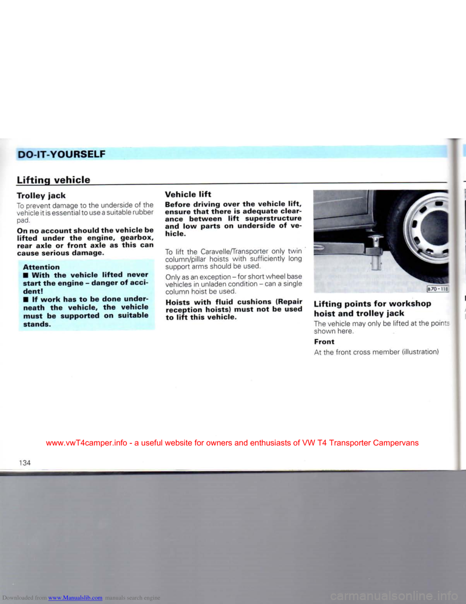
The vehicle may only be
lifted
at the poin:
shown here.
Front
At the
front
cross member (illustration) At
us
134
www.vwT4camper.info - a useful website for owners and enthusiasts of VW T4 Transporter Campervans
Page 137 of 164
Downloaded from www.Manualslib.com manuals search engine
DO-IT-YOURSELF
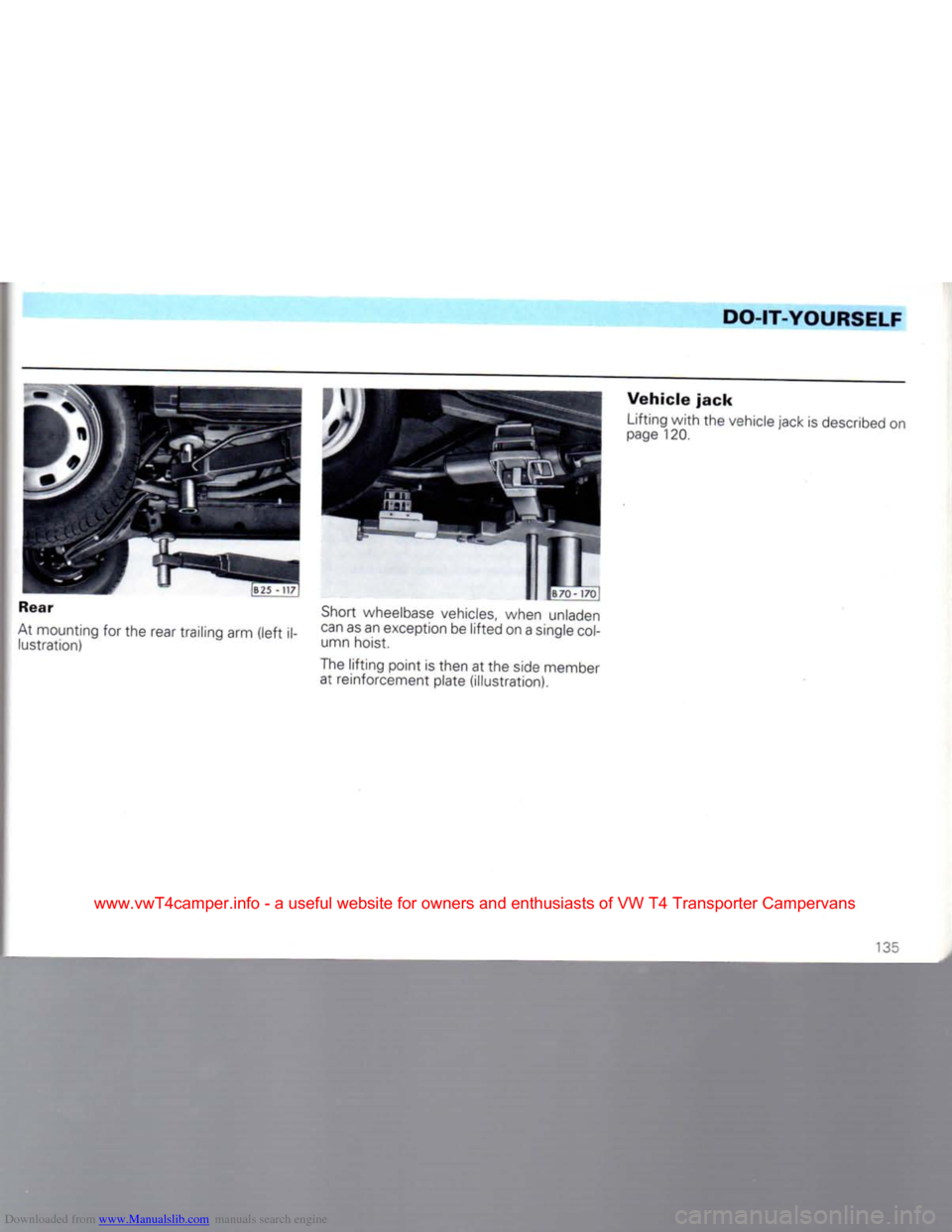
Rear
At mounting for the rear trailing arm (left i lustration) Short wheelbase vehicles, when unladen
can as an exception be lifted on a single
col
umn hoist.
The lifting point is then at the side member at reinforcement plate (illustration).
Vehicle
jack
Lifting with the vehicle jack is described on
page 120.
135
www.vwT4camper.info - a useful website for owners and enthusiasts of VW T4 Transporter Campervans
Page 138 of 164
Downloaded from www.Manualslib.com manuals search engine
TECHNICAL
DESCRIPTION
Engine
• 4 stroke petrol/Diesel engine, trans
verse
installation
• 4/5 cylinders in-line
• Cast-iron cylinder block
• 5/6 bearing crankshaft
• Sheet metal sump
• Alloy cylinder head
• Valves operated via toothed belt and overhead camshaft
• Maintenance free valve gear
with
hy draulic tappets
• Cooling system filled for life of vehicle
• Radiator
with
separate expansion tank • Electric radiator fan controlled by ther-
moswitch
• Maintenance free electronic ignition
• Long-life spark plugs
• Optical and acoustic oil pressure warn ing
• Low maintenance battery
with
high starting capacity
• Long-life low maintenance V-belts
• Thermostatically controlled intake air preheating
• Dry air cleaner
with
paper element • Fuel
injection
engines
have fully
electronic engine management (combined
control of injection and ignition systems).
• Emission control system
with
Lambda probe on petrol engines (not in all Export
markets)
•
Diesel
engines
with
distributor injec
tion
pump
with
cold start aid,
filter
preheat
ing,
self-bleeding fuel system
• Long life exhaust system.
'36
www.vwT4camper.info - a useful website for owners and enthusiasts of VW T4 Transporter Campervans
Page 139 of 164
Downloaded from www.Manualslib.com manuals search engine
TECHNICAL
DESCRIPTION
Emission
control
system<122>
The exhaust emission control system effec
tively reduces
the
amount
of
pollutants
in
the exhaust gas.
Petrol
engines
The main parts
of the
emission control
sys
tem
are
•
a
mixture formation system which guar antees very exact composition
of
the air/pe
trol
mixture
at all
engine speeds
•
the
catalytic converter
•
the
Lambda probe1'
The
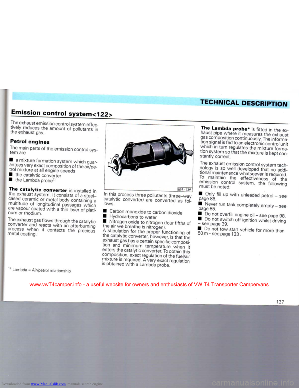
catalytic
converter
is
installed
in
the exhaust system.
It
consists
of a
steel-
cased
ceramic
or
metal body containing
a
multitude
of
longitudinal
passages
which
are vapour coated
with
a
thin
layer
of
plati
num
or
rhodium.
The exhaust gas flows through
the
catalytic converter
and
reacts
with
an
afterburning
process
when
it
contacts
the
precious
metal coating.
Lambda
=
Air/petrol relationship
)B19-
129
In
this process three pollutants (three-way
catalytic converter)
are
converted
as
fol
lows.
• Carbon monoxide
to
carbon dioxide
• Hydrocarbons
to
water
• Nitrogen oxide
to
nitrogen
(four
fifths
of
the
air we
breathe
is
nitrogen).
A
stipulation
for the
proper functioning
of
the catalytic converter, however,
is
that
the
exhaust gas has
a
certain specific composi
tion
and
minimum temperature when
it
enters
the
catalytic converter. To obtain this
composition, exact regulation
of the
fuel/air mixture
is
required. Avery exact regulation
is
obtained
with
a
Lambda probe. The Lambda
probe*
is
fitted
in the ex
haust pipe where
it
measures
the
exhaust
gas
composition continuously. The informa
tion
signal
is
fed
to
an electronic control
unit
which
in
turn
regulates
the
mixture forma
tion
system so
that
the
mixture
is
kept
con
stantly correct.
The exhaust emission control system tech nology
is so
well developed
that
no
addi
tional maintenance whatsoever
is
required.
To
maintain
the
effectiveness
of the
emission
control system,
the
following
must
be
noted:
• Only
fill
up
with
unleaded petrol
- see
page
86.
• Never
run
tank completely empty
-
see page
85.
•
Do not
overfill engine
oil -
see page
98.
•
Do not
switch
off
ignition whilst driving - see page
39.
•
Do not tow
start vehicle
for
more than 50 m-see page 133.
137
www.vwT4camper.info - a useful website for owners and enthusiasts of VW T4 Transporter Campervans
Page 140 of 164
Downloaded from www.Manualslib.com manuals search engine
TECHNICAL
DESCRIPTION
Attention
Due to high temperatures which
can occur in the catalytic
con
verter in very unfavourable conditions, the vehicle should not be parked so that the catalyt
ic converter can come into
con
tact with inflammable materials.
If whilst driving, the engine mis
fires, loses power and runs uneven ly,
this
could be due to a fault in the ignition system. In a
case
like this,
unburnt fuel can enter the exhaust
system and then escape to atmos
phere.
Furthermore, the catalytic
converter could become damaged
due to overheating. The vehicle
speed must be reduced immediately
and the defect should be eliminated
at the nearest Volkswagen dealer.
Note
Even
in the
case
of a
perfectly working
ex
haust emission control system there can, under certain engine operating conditions,
be
a
sulphur-type exhaust
smell.
This
depends upon
the
sulphur content
in
the fuel being
used.
Quite often this can
be
remedied
by
select
ing another brand
of
fuel
or,
filling
up
with
unleaded premium petrol.
50
kW
Diesel
engine
An
oxidation catalytic converter
is
fitted
in
the exhaust system
of
this Diesel engine.
It
consists
of
a steel-cased ceramic body
con
taining
a
multitude
of
longitudinal
passages
which are vapour coated
with
platinum. The catalytic converter largely eliminates
the
unpleasant smelling hydrocarbons
and
turns carbon monoxide
into
carbon dioxide.
In addition
an
exhaust
gas
turbocharger
forces
air
into
the
cylinder, causing
the
en
gine
to
operate
with
a high
excess
of
air. The
fuel which is then injected in is so complete ly
burnt,
that
under
full
load soot is no longer
visible
in the
exhaust.
As
the
diesel engine catalytic converter
does
not get
hotter than
a
conventional
ex
haust system, under normal conditions
there
is
nothing special
to be
noted, this
applies
also
to
parking.
The system does
not
require any additional
care
or
maintenance.
Activated
charcoal
filter*
Vehicles
with
a
regulated catalytic
con
verter,
in
Germany
and
other export countries, have
a
fuel system which
in
cludes
an activated charcoal
filter
(petrol vapour accumulator).
The activated charcoal
filter
prevents
the
fuel vapour escaping
into
the
atmosphere.
These
vapours
pass
into
a
container filled
with
activated charcoal and, when
the en
gine
is
stationary they
are
accumulated
in
the activated charcoal. When
the
engine
is
running,
the
container
is
automatically
ventilated
by
opening
a
valve
and the
fuel
vapour
is fed
into
the
engine
for
combus
tion.
The system works completely automati
cally
and
is
maintenance-free.
138
www.vwT4camper.info - a useful website for owners and enthusiasts of VW T4 Transporter Campervans