VOLKSWAGEN CARAVELLE 1992 T4 / 4.G Workshop Manual
Manufacturer: VOLKSWAGEN, Model Year: 1992, Model line: CARAVELLE, Model: VOLKSWAGEN CARAVELLE 1992 T4 / 4.GPages: 164, PDF Size: 25 MB
Page 51 of 164
Downloaded from www.Manualslib.com manuals search engine
CONTROLS
AND
EQUIPMENT
6-Alternator
Q
~ne warning lamp comes on when the
igni-
I
on
is
switched on and must go out when
She
engine
is
started.
i the warning lamp comes on when driving,
stop,
switch
engine
off
and
check
the
alternator V-belt.
f the V-belt
is
broken or loose do not
drive
on with
a
vehicle which
has a 4 cylinder
engine
because the coolant pump
is
then
no
longer being driven. The V-belt must
be
tensioned
or
renewed.
ehicles with
a 5
cylinder engine
can
nor
mally
be
driven to the nearest Volkswagen
dealer when
the
V-belt
is
broken
or
loose oecause
the
coolant pump
is
driven separ
ately but then the battery will discharge
con
tinuously
and all
non-essential electrical consumers should
be
switched
off.
f the warning lamp comes on although
the
belt
is
not broken, one can normally drive on
to
the nearest Volkswagen dealer (all engine
types)
but the
battery will then discharge
continuously
- see
previous paragraph.
7-Glow
plugs
W
(Diesel engines only)
When
the engine
is cold
the warning lamp comes on when key
is
turned to Drive
posi
tion
(ignition on).
If
the warning lamp does not come
on,
there
is
a
defect in the glow plug system
-
call
in
expert assistance.
When
the
lamp goes out,
start
the engine
immediately
-
see page
38.
When
the
engine
is warm the
glow plug
lamp
does
not
come on -the engine can
be
started straight
away.
(®)
-
Anti-locking
Brake
System
(ABS)*
The operational readiness
of the
essential electrical components
of the ABS are
checked,
both before moving off and when
driving,
by an electronic monitoring system.
The warning lamp lights up when
the
igni
tion
is
switched on and
it
must go out again, at the latest, after the engine
has
started.
If
the warning lamp does not go out
or if it
comes on when driving the system
is
not
in
order.
The
vehicle can then only
be
braked
with
the
normal system
-
that
is
without
ABS-.The vehicle must be taken to a Volks
wagen Dealership
as
soon
as
possible.
Further details on ABS
is
given on page
30.
<]1i>
-
Trailer
turn
signals
The warning lamp
*
flashes when turn
sig
nals are switched on when towing
a
trailer.
If a
turn signal fails on the trailer or vehicle,
the warning lamp does not flash.
www.vwT4camper.info - a useful website for owners and enthusiasts of VW T4 Transporter Campervans
Page 52 of 164
Downloaded from www.Manualslib.com manuals search engine
CONTROLS AND EQUIPMENT
JB70-
1251
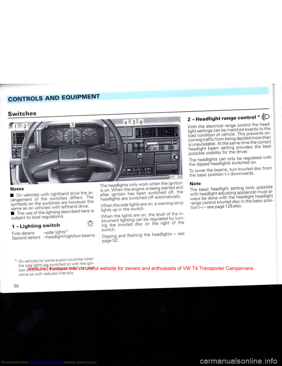
Switches
Notes
• On vehicles
with
righthand drive the ar rangement of the switches differs. The
symbols
on the switches are however the
same
as on vehicles
with
lefthand drive.
• The use of the lighting described here is subject to local regulations.
1 -
Lighting
switch
-n
First
detent -side lights11
Second
detent -headlight high/low beams
The
headlights only work when the ignition
is
on. When the engine is being started and
after ignition has been switched off, the headlights are switched off automatically.
When
the side lights are on, a warning lamp lights up in the switch.
When
the lights are on, the level of the in strument lighting can be regulated by turning the knurled disc on the
right
of the
switch.
Dipping and flashing the headlights - see
page
52. 2 -
Headlight
range
control
* %\_)
With the electrical range control the
head
light settings can be matched exactly to the
load
condition of vehicle. This prevents on
coming traffic from being
dazzled
more than
is
unavoidable. At the same time the correct headlight beam setting provides the best
possible
visibility for the driver.
The
headlights can only be regulated
with
the dipped headlights switched on.
To
lower the beams,
turn
knurled disc from
the
basic
position (-) downwards.
Note
The
basic
headlight setting (only possible
with
headlight adjusting appliance) must al
ways
be done
with
the headlight headlight range control knurled disc in the
basic
posi
tion (-) - see page 128
also.
On
vehicles for some export countries when
the side lights are switched on
with
the igni
tion switched on, the dipped headlights also
come
on
with
reduced intensity.
50
www.vwT4camper.info - a useful website for owners and enthusiasts of VW T4 Transporter Campervans
Page 53 of 164
Downloaded from www.Manualslib.com manuals search engine
CONTROLS
AND
EQUIPMENT
3
-
Emergency lights .
nen the emergency lights are on, a warn-
'z lamp in the switch flashes as well.
Ine system also works when the ignition is
;
.-.itched off.
4
-
Knurled wheel for seat
^Jf
heating*
~~e cushion and backrest of the
front
seats
:
=
n
be heated electrically when the ignition
s
on.
_~e
heating is switched on and regulated .vth the knurled wheel.
•
switch heating off,
turn
knurled wheel to
:_e
left
to the detent position.
5
-
Heated rear window
QpJ
The
heating works only when ignition is on.
When
heater is on a lamp in the switch lights up.
As soon
as
window
is
clear,
switch element
off. The
reduced
current consumption helps
to re
duce
the
fuel
consumption
- see
also
page
80.
On
vehicles
with
electrically adjustable ex
terior mirrors the mirrors are heated as long
as
the rear window heating is switched on.
6
-
Fog lights •/
|Q
Rear fog light
First
detent - fog lights
Second
-
front
and rear fog
detent lights, or rear fog
light
only
At the second position a warning lamp in the switch comes on.
The fog lights
work
with
the side lights (ignition on), low or high beams.
The rear fog light
works only
with
the fog lights or
with
the low or high beams.
Due
to the amount of
dazzle
it
causes
the
rear
fog
light
should only be switched on
when the visibility is very poor (in Germany
for example, below 50 metres).
Note
The
electrical system of the factory
fitted
tow bar* is wired-up so
that
when towing
a
trailer
fitted
with
rear fog lights, the rear
fog
light
on the towing vehicle are automati
cally
switched off.
51
www.vwT4camper.info - a useful website for owners and enthusiasts of VW T4 Transporter Campervans
Page 54 of 164
Downloaded from www.Manualslib.com manuals search engine
CONTROLS
AND EQUIPMENT
Turn signal and dip
lever
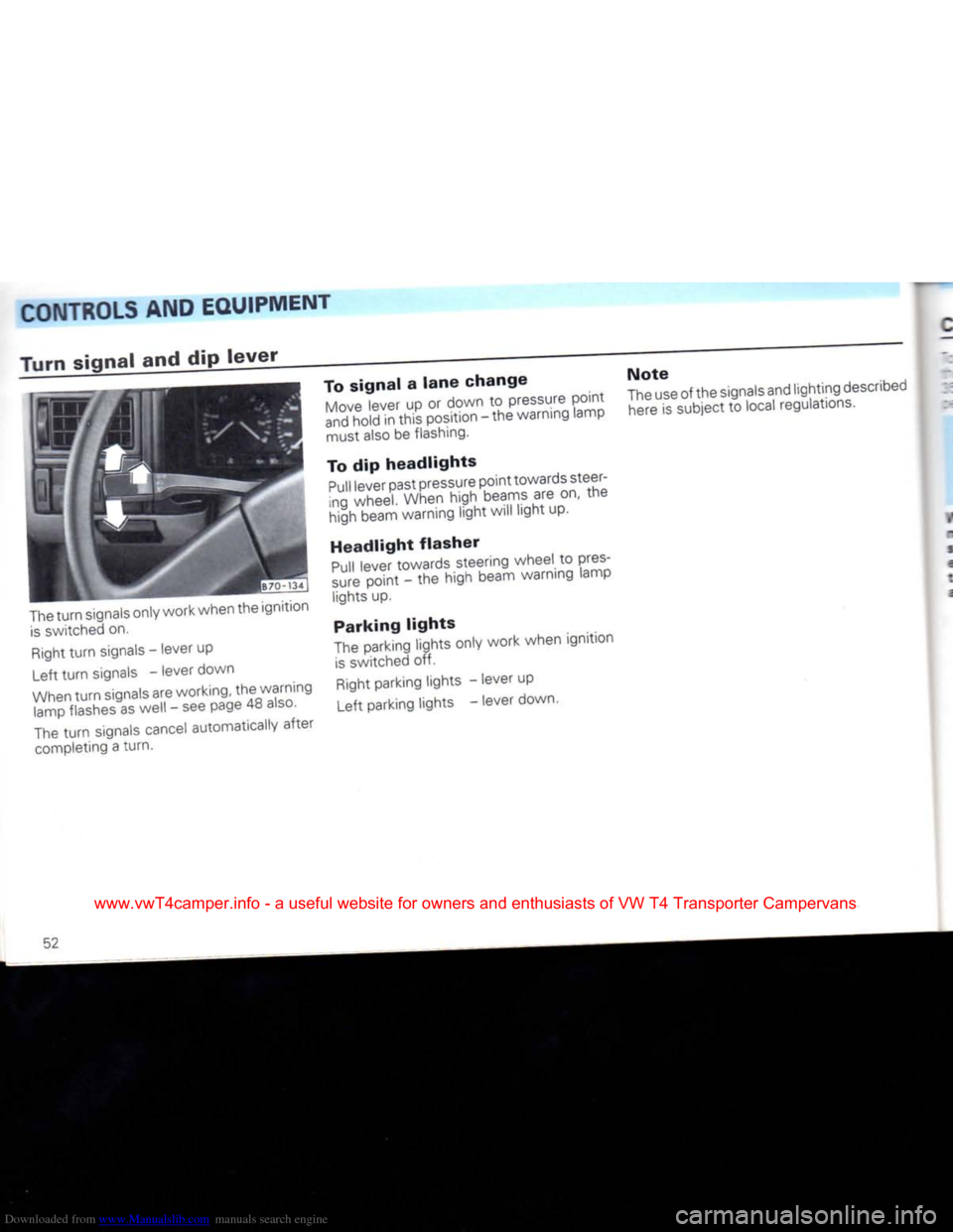
The
turn
signals only work when the ignition
is
switched on.
Right
turn
signals - lever up
Left
turn
signals - lever down
When
turn
signals are working, the warning lamp flashes as well - see page 48
also.
The
turn
signals cancel automatically after
completing a turn. To
signal
a
lane
change
Move
lever up or down to pressure point
and
hold in this position - the warning lamp must also be flashing.
To dip
headlights
Pull
lever past pressure point towards steer
ing wheel. When high beams are on, the
high beam warning light will light up.
Headlight
flasher
Pull
lever towards steering wheel to pres
sure
point - the high beam warning lamp lights up.
Parking
lights
The
parking lights only work when ignition
is
switched off.
Right
parking lights - lever up
Left parking lights - lever down. Note
The
use of the signals and lighting described
here
is subject to local regulations.
52
www.vwT4camper.info - a useful website for owners and enthusiasts of VW T4 Transporter Campervans
Page 55 of 164
Downloaded from www.Manualslib.com manuals search engine
CONTROLS AND
EQUIPMENT
Cruise
control
system* : "elieve the
foot
on the accelerator pedal
~ -
s system can hold any speed aboveabout
is'mits.
Attention
The
cruise
control
system
should not be used in
dense
traffic
and
poor
road
conditions
(slippery
surfaces,
aquaplaning,
gravel).
iVhen
system
is
switched
on do not
•nove
into
neutral
without
depres
sing the
clutch
pedal,
otherwise
the
engine
will
race
and can,
under
cer
tain
circumstances,
become
dam
aged.
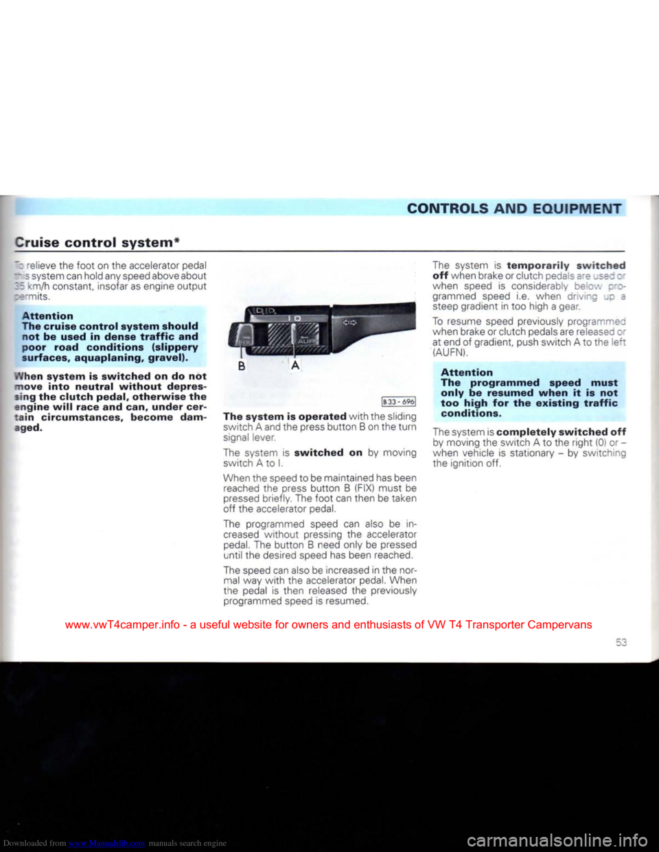
B
A
|B
33
- 696[
The
system
is
operated
with
the sliding switch A and the press
button
B on the
turn
signal lever.
The system is
switched
on by moving switch A to I.
When the speed to be maintained has been reached the press
button
B (FIX) must be
pressed
briefly. The
foot
can then be taken
off the accelerator pedal.
The programmed speed can also be in
creased
without
pressing the accelerator
pedal.
The
button
B need only be pressed
until
the desired speed has been reached.
The speed can also be increased in the nor mal way
with
the accelerator pedal. When
the pedal is then released the previously programmed speed is resumed. The system is
temporarily
switched
off when brake or clutch pedals sre _se; : •
when speed is considerably bee.', z'z- grammed speed i.e. when driving _c =
steep gradient in too high a gear.
To resume speed previously programmed
when brake or clutch pedals are releasee or at end of gradient, push switch A to the
left
(AUFN).
Attention
The
programmed
speed
must
only
be
resumed
when
it is not
too
high
for the
existing
traffic
conditions.
The system is
completely
switched
off by moving the switch A to the
right
(0) or -
when vehicle is stationary - by switching
the ignition off.
www.vwT4camper.info - a useful website for owners and enthusiasts of VW T4 Transporter Campervans
Page 56 of 164
Downloaded from www.Manualslib.com manuals search engine
CONTROLS AND EQUIPMENT
Windscreen
wiper
and
washer
system
Wipers
and washers only work when igni
tion is switched on.
The
heated
windscreen
washer
jets*
are switched on when the ignition is switched on and the amount of heat is regulated automatically according to the ambi
ent temperature
When
it is freezing, check
that
the wiper
blades
are not frozen to the glass before
switching the wipers on for the
first
time.
Windscreen
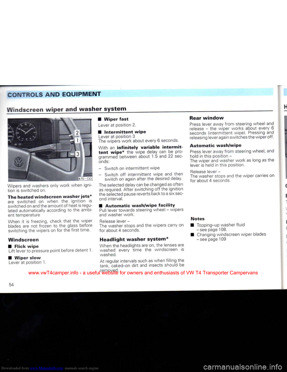
• Flick
wipe
Lift lever to pressure point before detent 1.
•
Wiper
slow
Lever
at position 1. •
Wiper
fast
Lever
at position 2.
•
Intermittent
wipe
Lever
at position 3
The
wipers work about every 6
seconds.
With an
infinitely
variable
intermit
tent
wipe*
the wipe delay can be programmed between about 1.5 and 22
sec
onds:
- Switch on
intermittent
wipe
- Switch off
intermittent
wipe and then switch on again after the desired delay.
The
selected delay can be changed as often
as
required. After switching off the ignition
the selected pause reverts back to a six
sec
ond interval.
•
Automatic
wash/wipe
facility
Pull
lever towards steering wheel - wipers
and
washer work.
Release
lever -
The
washer stops and the wipers carry on
for about 4
seconds.
Headlight washer system*
When
the headlights are on, the lenses are
washed
every time the windscreen is
washed.
At regular intervals such as when filling the
tank, caked-on
dirt
and insects should be
removed.
Rear
window
Press
lever away from steering wheel and
release
- the wiper works about every 6
seconds
(intermittent
wipe).
Pressing
and
releasing
lever again switches the wiper off.
Automatic
wash/wipe
Press
lever away from steering wheel, and
hold in this position -
The
wiper and washer work as long as the
lever
is held in this position.
Release
lever -
The
washer stops and the wiper carries on
for about 4
seconds.
Notes
Topping-up washer fluid
- see page 108.
Changing
windscreen wiper blades
- see page 109
54
www.vwT4camper.info - a useful website for owners and enthusiasts of VW T4 Transporter Campervans
Page 57 of 164
Downloaded from www.Manualslib.com manuals search engine
CONTROLS
AND
EQUIPMENT
Heating
and
ventilation
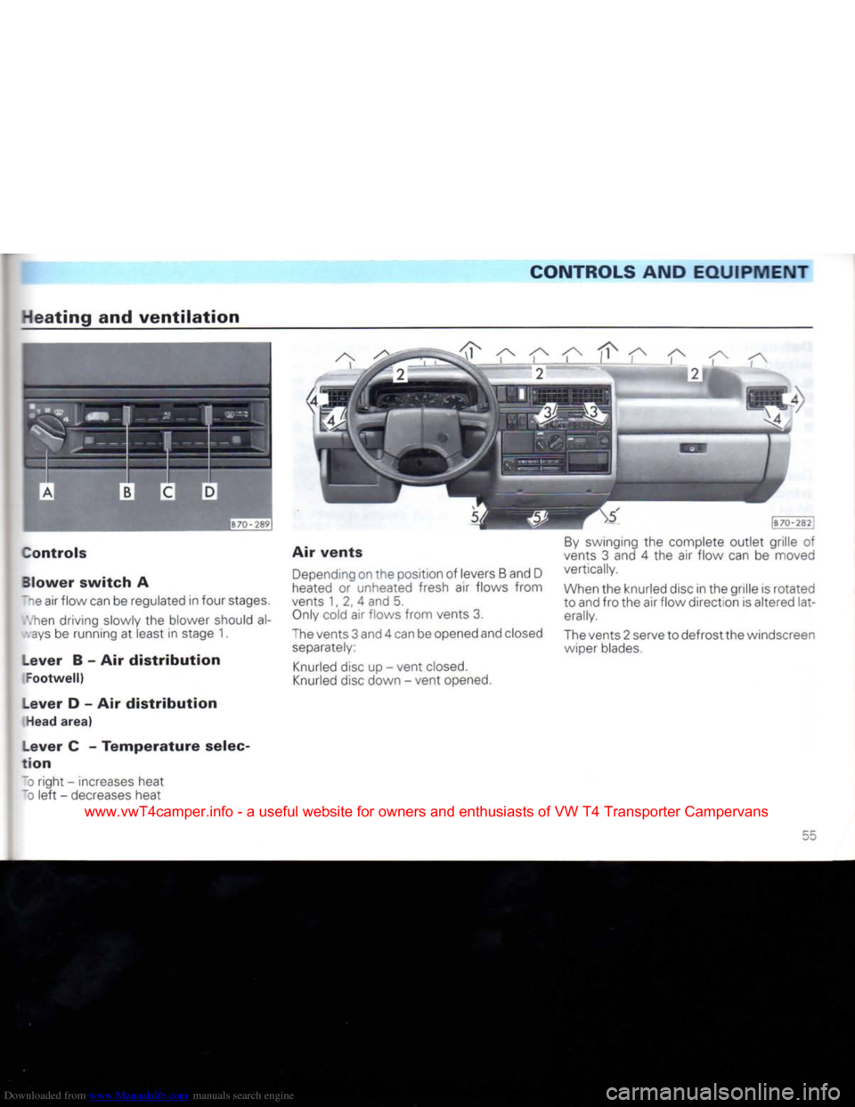
Controls
Blower
switch
A
~~e air flow can be regulated in four stages.
.hen
driving slowly the blower should al-
ays
be running at least in stage 1.
Lever
B - Air
distribution
Footwell)
Lever
D - Air
distribution
Head
area)
Lever
C -
Temperature
selec
tion
To
right - increases heat
~D
left
- decreases heat Air
vents
Depending
on the position of levers B and D
heated
or unheated fresh air flows from
vents 1, 2, 4 and 5.
Only
cold air flows from vents 3.
The
vents 3 and 4 can be opened and closed
separately:
Knurled
disc up - vent
closed.
Knurled
disc down - vent opened.
By
swinging the complete outlet grille of
vents 3 and 4 the air flow can be moved
vertically.
When
the knurled disc in the grille is rotated
to and fro the air flow direction is altered lat
erally.
The
vents 2 serve to defrost the windscreen wiper blades.
55
www.vwT4camper.info - a useful website for owners and enthusiasts of VW T4 Transporter Campervans
Page 58 of 164
Downloaded from www.Manualslib.com manuals search engine
CONTROLS AND
EQUIPMENT
Defrosting
windscreen
and side
windows
• Rotary switch A to stage 3
• All levers to the
right
• Vents 3 closed
• Adjust vents 4 so
that
additional warm air can be directed to the side windows.
Demisting
windscreen
and side
windows
When the windows mist up due to high air humidity, e.g. when it is raining, we recom
mend the following settings:
• Rotary switch A to stage 2 or 3 • Lever C if necessary, to
right
into
heating range
• Lever D to
right
• Vents 3 closed
• Adjust vents 4 so
that
additional warm air
can
be directed to the side windows.
Heating
interior
quickly
• Rotary switch A to stage 3 • Lever C to
right
• Lever B to
left
• Vents 3 closed
• Vents 4 opened.
Heating
interior
comfortably
When the windows are clear and the de sired interior temperature has been re
ached,
we recommend the following set
tings:
• Rotary switch A to stage 1 or 2
• Lever C at the desired heat
output
• Levers B and D set to desired air distribu tion. If the windscreen once again becomes misted up, move levers B and D to the
right.
• Vents 3 closed
• With vents 4 the desired amount of warm air and the air flow direction can be set.
Ventilation
(fresh
air
operation)
With the following settings, unheated fresh air flows from vents 3 and 4:
• Rotary switch A to desired stage
• Lever B to
right
and lever D to
left
• Lever C fully to
left
• Vents 3 and 4 open If required, levers B and D can be set to
other positions.
Notes
• To ensure
that
the heating and ventila
tion
can work properly, the air inlet in
front
of the windscreen should be kept free of
ice,
snow and
leaves.
• All controls except the rotary switch A
can
be set to any intermediate position,
• To prevent the windows from misting up the blower should be running slowly when driving at low
speeds.
• The heat
output
depends on the coolant temperature - the
full
heat
output
is there
fore only available when the engine is warm.
• The stale air
escapes
through ventilation slots in the luggage compartment/loading
area
side panel trim. Therefore these slots should not be covered.
On
vehicles
with
a
full-width
partition and
on the Pick-up and Double Cab models the
stale air
escapes
through slots in the
front
doors.
56
www.vwT4camper.info - a useful website for owners and enthusiasts of VW T4 Transporter Campervans
Page 59 of 164
Downloaded from www.Manualslib.com manuals search engine
CONTROLS AND
EQUIPMENT
Air
conditioner*
in cab
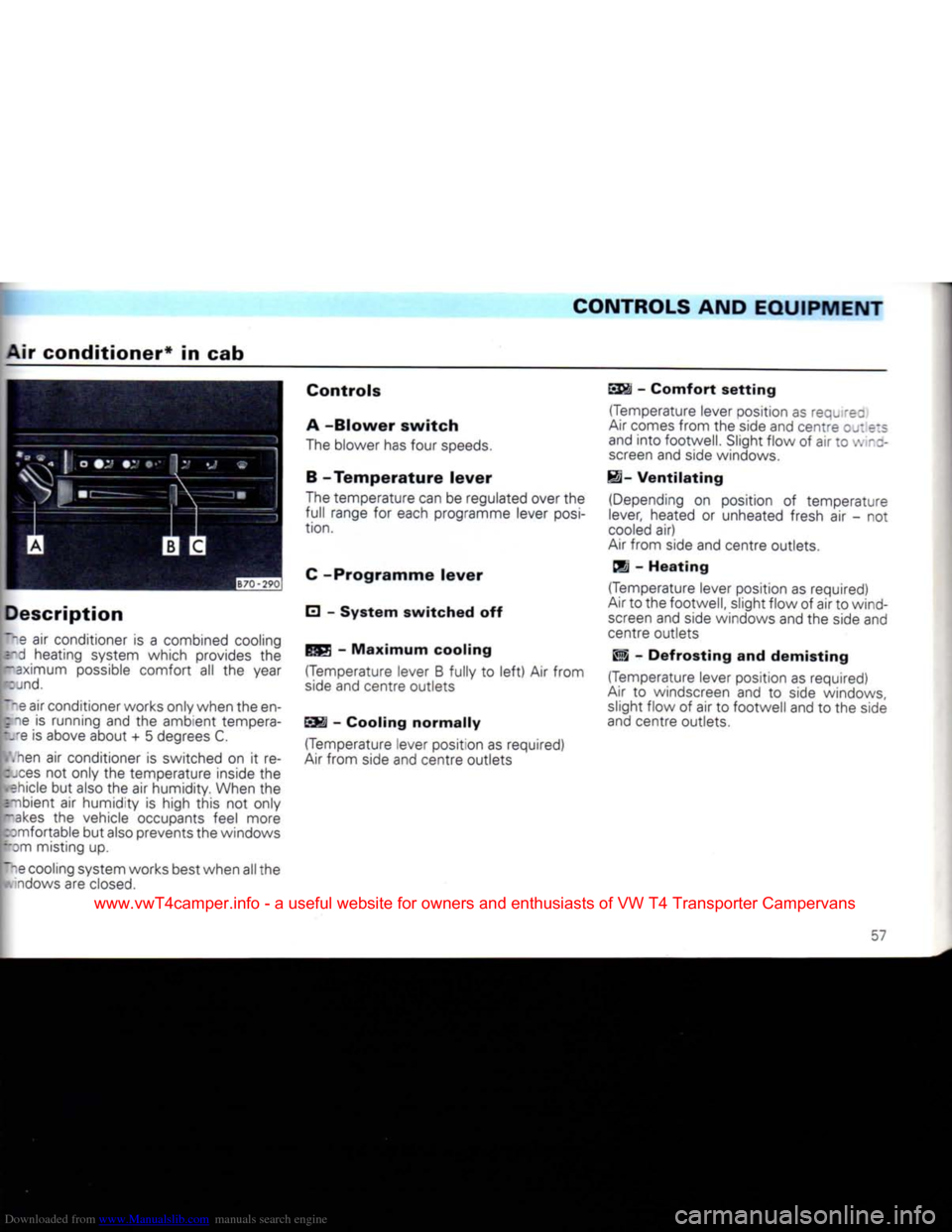
Description
T".e air conditioner is a combined cooling srd heating system which provides the
r-aximum possible comfort all the year
rcjnd.
Tpe air conditioner works only when the en-
pie
is running and the ambient tempera- t.re is above about + 5 degrees C.
,ien air conditioner is switched on it re-
bjces not only the temperature inside the
•
ehicle but also the air humidity. When the
=-nbient
air humidity is high this not only
Iakes
the vehicle occupants feel more
comfortable but also prevents the windows
""Dm
misting up.
~ne cooling system works best when all the
v.indows are closed.
Controls
A
-Blower
switch
The blower has four speeds.
B -
Temperature
lever
The temperature can be regulated over the
full range for each programme lever
posi
tion.
C
-Programme
lever
E] -
System
switched
off -
Maximum
cooling
(Temperature lever B fully to
left)
Air from
side and centre outlets
SSI -
Cooling
normally
(Temperature lever position as required)
Air
from side and centre outlets
SS§i
-
Comfort
setting
(Temperature lever position as requ rez
Air
comes from the side and centre
OJ:
e:s
and into footwell. Slight flow of air to
•:.
-z- screen and side windows.
H-
Ventilating
(Depending on position of temperature
lever, heated or unheated fresh air - not
cooled
air)
Air
from side and centre outlets,
dj -
Heating
(Temperature lever position as required)
Air
to the footwell, slight flow of air to wind screen and side windows and the side and
centre outlets
Wi -
Defrosting
and
demisting
(Temperature lever position as required)
Air
to windscreen and to side windows, slight flow of air to footwell and to the side
and centre outlets.
57
www.vwT4camper.info - a useful website for owners and enthusiasts of VW T4 Transporter Campervans
Page 60 of 164
Downloaded from www.Manualslib.com manuals search engine
CONTROLS
AND EQUIPMENT
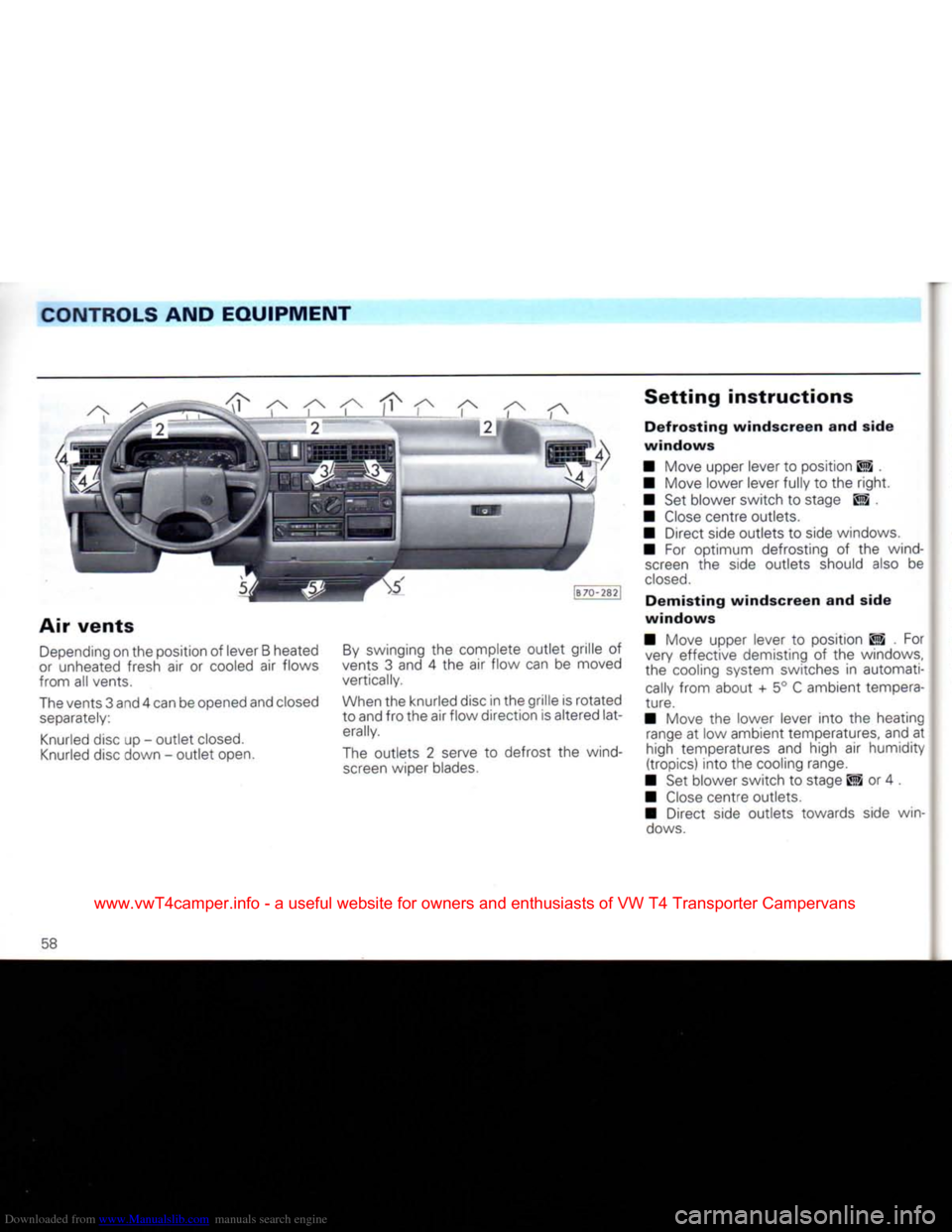
Air
vents
Depending
on the position of lever B heated
or
unheated fresh air or cooled air flows
from all vents.
The
vents 3 and 4 can be opened and closed
separately:
Knurled
disc up - outlet
closed.
Knurled
disc down - outlet open.
By
swinging the complete outlet grille of
vents 3 and 4 the air flow can be moved
vertically.
When
the knurled disc in the grille is rotated
to and fro the air flow direction is altered lat
erally.
The
outlets 2 serve to defrost the wind
screen
wiper blades.
Setting
instructions
Defrosting
windscreen
and side
windows
• Move upper lever to position ES .
• Move lower lever fully to the
right.
• Set blower switch to stage ES , •
Close
centre outlets.
• Direct side outlets to side windows.
• For optimum defrosting of the wind
screen
the side outlets should also be
closed.
Demisting
windscreen
and side
windows
• Move upper lever to position ES . For very effective demisting of the windows,
the cooling system switches in automati
cally
from about + 5° C ambient tempera
ture.
• Move the lower lever into the heating
range
at low ambient temperatures, and at
high temperatures and high air humidity
(tropics) into the cooling range.
• Set blower switch to stage El or 4 .
•
Close
centre outlets.
• Direct side outlets towards side win
dows.
58
www.vwT4camper.info - a useful website for owners and enthusiasts of VW T4 Transporter Campervans