tire pressure VOLKSWAGEN CORRADO 1990 User Guide
[x] Cancel search | Manufacturer: VOLKSWAGEN, Model Year: 1990, Model line: CORRADO, Model: VOLKSWAGEN CORRADO 1990Pages: 906, PDF Size: 6.56 MB
Page 276 of 906

* SUSPENSION UNIFORM INSPECTION GUIDELINES *
Article Text (p. 65)
1990 Volkswagen Corrado
For Volkswagen Technical Site: http://vw.belcom.ru
Copyright © 1998 Mitchell Repair Information Company, LLC
Thursday, March 23, 2000 09:39PMÄÄÄÄÄÄÄÄÄÄÄÄÄÄÄÄÄÄÄÄÄÄÄÄÄÄÄÄÄÅÄÄÄÄÄÄÅÄÄÄÄÄÄÄÄÄÄÄÄÄÄÄÄÄÄÄÄÄÄÄÄÄÄÄÄÄÄÄÄÄThreads stripped (threads
³ A ³ Require replacement of
missing)
³ ³ component with stripped threads.
ÄÄÄÄÄÄÄÄÄÄÄÄÄÄÄÄÄÄÄÄÄÄÄÄÄÄÄÄÄÁÄÄÄÄÄÄÁÄÄÄÄÄÄÄÄÄÄÄÄÄÄÄÄÄÄÄÄÄÄÄÄÄÄÄÄÄÄÄÄÄNOTE: (1) Some manufacturers require replacement of all studs on that
wheel if two or more studs or nuts on the same wheel are
broken or missing.
(2) Only required if removing wheel.
ÄÄÄÄÄÄÄÄÄÄÄÄÄÄÄÄÄÄÄÄÄÄÄÄÄÄÄÄÄÄÄÄÄÄÄÄÄÄÄÄÄÄÄÄÄÄÄÄÄÄÄÄÄÄÄÄÄÄÄÄÄÄÄÄÄÄÄÄÄÄ WHEELS
WARNING: Mounting a regular tire on a high-pressure compact spare
wheel is not permitted. Attempting to mount a tire of one
diameter on a wheel of a different diameter or flange type
may result in serious injury or death. If the wheel
identification stamp is not legible, or cannot be found,
DO NOT use the wheel until the size and type have been
properly identified. Wheels of different diameter, offset,
or width cannot be mixed on the same axle. Bead seat tapers
cannot be interchanged.
WHEELS
ÄÄÄÄÄÄÄÄÄÄÄÄÄÄÄÄÄÄÄÄÄÄÄÄÄÄÄÂÄÄÄÄÄÄÂÄÄÄÄÄÄÄÄÄÄÄÄÄÄÄÄÄÄÄÄÄÄÄÄÄÄÄÄÄÄÄÄÄÄÄCondition
³ Code ³ Procedure
ÄÄÄÄÄÄÄÄÄÄÄÄÄÄÄÄÄÄÄÄÄÄÄÄÄÄÄÅÄÄÄÄÄÄÅÄÄÄÄÄÄÄÄÄÄÄÄÄÄÄÄÄÄÄÄÄÄÄÄÄÄÄÄÄÄÄÄÄÄÄBead leaking, caused by
³ A ³ Require repair or replacement.
wheel rim flange
³ ³ See caution below.
ÄÄÄÄÄÄÄÄÄÄÄÄÄÄÄÄÄÄÄÄÄÄÄÄÄÄÄÁÄÄÄÄÄÄÁÄÄÄÄÄÄÄÄÄÄÄÄÄÄÄÄÄÄÄÄÄÄÄÄÄÄÄÄÄÄÄÄÄÄÄCAUTION: DO NOT attempt to correct a bent wheel rim.
ÄÄÄÄÄÄÄÄÄÄÄÄÄÄÄÄÄÄÄÄÄÄÄÄÄÄÄÂÄÄÄÄÄÄÂÄÄÄÄÄÄÄÄÄÄÄÄÄÄÄÄÄÄÄÄÄÄÄÄÄÄÄÄÄÄÄÄÄÄÄBent wheel hub mounting
³ A ³ Require replacement.
surface
³ ³
ÄÄÄÄÄÄÄÄÄÄÄÄÄÄÄÄÄÄÄÄÄÄÄÄÄÄÄÅÄÄÄÄÄÄÅÄÄÄÄÄÄÄÄÄÄÄÄÄÄÄÄÄÄÄÄÄÄÄÄÄÄÄÄÄÄÄÄÄÄÄBent wheel rim, causing
³ B,2 ³ Suggest replacement.
vibration
³ ³ See caution above.
ÄÄÄÄÄÄÄÄÄÄÄÄÄÄÄÄÄÄÄÄÄÄÄÄÄÄÄÅÄÄÄÄÄÄÅÄÄÄÄÄÄÄÄÄÄÄÄÄÄÄÄÄÄÄÄÄÄÄÄÄÄÄÄÄÄÄÄÄÄÄBroken
³ A ³ Require replacement.
ÄÄÄÄÄÄÄÄÄÄÄÄÄÄÄÄÄÄÄÄÄÄÄÄÄÄÄÅÄÄÄÄÄÄÅÄÄÄÄÄÄÄÄÄÄÄÄÄÄÄÄÄÄÄÄÄÄÄÄÄÄÄÄÄÄÄÄÄÄÄCast wheel porous, causing
³ A ³ Require repair or replacement.
a leak
³ ³
ÄÄÄÄÄÄÄÄÄÄÄÄÄÄÄÄÄÄÄÄÄÄÄÄÄÄÄÅÄÄÄÄÄÄÅÄÄÄÄÄÄÄÄÄÄÄÄÄÄÄÄÄÄÄÄÄÄÄÄÄÄÄÄÄÄÄÄÄÄÄClip-on balance weight is
³ B,2 ³ Suggest replacement.
incorrect type for wheel
³ ³ rim flange
³ ³
ÄÄÄÄÄÄÄÄÄÄÄÄÄÄÄÄÄÄÄÄÄÄÄÄÄÄÄÅÄÄÄÄÄÄÅÄÄÄÄÄÄÄÄÄÄÄÄÄÄÄÄÄÄÄÄÄÄÄÄÄÄÄÄÄÄÄÄÄÄÄCorrosion, affecting
³ A ³ Require replacement.
structural integrity
³ ³
ÄÄÄÄÄÄÄÄÄÄÄÄÄÄÄÄÄÄÄÄÄÄÄÄÄÄÄÅÄÄÄÄÄÄÅÄÄÄÄÄÄÄÄÄÄÄÄÄÄÄÄÄÄÄÄÄÄÄÄÄÄÄÄÄÄÄÄÄÄÄCorrosion build-up on wheel
³ A ³ Require repair.
hub mounting surface
³ ³
ÄÄÄÄÄÄÄÄÄÄÄÄÄÄÄÄÄÄÄÄÄÄÄÄÄÄÄÅÄÄÄÄÄÄÅÄÄÄÄÄÄÄÄÄÄÄÄÄÄÄÄÄÄÄÄÄÄÄÄÄÄÄÄÄÄÄÄÄÄÄ
Page 319 of 906
A/C COMPRESSOR OIL CHECKING
Article Text
1990 Volkswagen Corrado
For Volkswagen Technical Site: http://vw.belcom.ru
Copyright © 1998 Mitchell Repair Information Company, LLC
Thursday, March 23, 2000 09:41PM
ARTICLE BEGINNING
1990 AIR CONDITIONING & HEAT
Compressor Oil Checking
ISOLATING COMPRESSOR
NOTE: Only compressors with stem-type service valves can be
isolated.
1) Connect service gauge set to the compressor service valves
and open compressor valves slightly (turn in clockwise). Start engine
and operate air conditioning. Slowly turn compressor suction valve
clockwise toward closed (front-seated) position.
2) When suction pressure is reduced to zero or less, turn off
engine and compressor and quickly turn suction valve stem in to full
front-seated position. Suction pressure should be slightly above zero.
Turn discharge valve into front-seated position.
3) To check oil level, slowly open compressor crankcase plug
to relieve any remaining pressure. After oil level is corrected, cap
service gauge ports on both valves. Back-seat suction service valve to
allow refrigerant to enter compressor. Open discharge valve halfway.
4) Loosen discharge service valve cap, allowing refrigerant
pressure to force air out of compressor. Back-seat service valve and
tighten cap. Compressor is now ready for operation.
REFRIGERANT OIL
Only new, pure, moisture-free refrigerant oil should be used
in the air conditioning system. This oil is highly refined and
dehydrated to a point where moisture content is less than 10 parts per
million. The oil container must be tightly closed at all times when
not in use, or moisture will be absorbed into the refrigerant oil from
the air.
SERVICING PRECAUTIONS
NOTE: Recent findings by the EPA indicate that refrigerant is
harmful to the earth's protective Ozone layer. When
discharging refrigerant, DO NOT allow refrigerant to enter
the atmosphere. If available, use refrigerant
recovery/recycle systems when discharging system. Always
follow manufacturer's instructions.
DISCHARGING SYSTEM PRECAUTIONS
If compressor has stem-type service valves, it can be
isolated and removed without discharging entire system. See ISOLATING
COMPRESSOR at the beginning of this article. Otherwise, discharge
system completely before loosening any fittings.
Page 327 of 906
A/C COMPRESSOR SERVICING
Article Text
1990 Volkswagen Corrado
For Volkswagen Technical Site: http://vw.belcom.ru
Copyright © 1998 Mitchell Repair Information Company, LLC
Thursday, March 23, 2000 09:41PM
ARTICLE BEGINNING
1990 AIR CONDITIONING & HEAT
Compressor Service
* PLEASE READ THIS FIRST *
CAUTION: When discharging air conditioning system, use only approved
refrigerant recovery/recycling equipment. Make every attempt
to avoid discharging refrigerant into the atmosphere.
ISOLATING COMPRESSOR
NOTE: Only compressors with stem-type service valves can be
isolated.
1) Connect service gauge set to the compressor service valves
and open compressor valves slightly (turn in clockwise). Start engine
and operate air conditioning. Slowly turn compressor suction valve
clockwise toward closed (front-seated) position.
2) When suction pressure is reduced to zero or less, turn off
engine and compressor and quickly turn suction valve stem in to full
front-seated position. Suction pressure should be slightly above zero.
Turn discharge valve into front-seated position.
3) To check oil level, slowly open compressor crankcase plug
to relieve any remaining pressure. After oil level is corrected, cap
service gauge ports on both valves. Back-seat suction service valve to
allow refrigerant to enter compressor. Open discharge valve halfway.
4) Loosen discharge service valve cap, allowing refrigerant
pressure to force air out of compressor. Back-seat service valve and
tighten cap. Compressor is now ready for operation.
REFRIGERANT OIL
Only new, pure, moisture-free refrigerant oil should be used
in the air conditioning system. This oil is highly refined and
dehydrated to a point where moisture content is less than 10 parts per
million. The oil container must be tightly closed at all times when
not in use, or moisture will be absorbed into the refrigerant oil from
the air.
DISCHARGING SYSTEM PRECAUTIONS
CAUTION: When discharging air conditioning system, use only approved
refrigerant recovery/recycling equipment. Make every attempt
to avoid discharging refrigerant into the atmosphere.
If compressor has stem-type service valves, it can be
isolated and removed without discharging entire system. Otherwise,
discharge system completely using approved refrigerant
Page 354 of 906
A/C SYSTEM PRECAUTIONS
Article Text
1990 Volkswagen Corrado
For Volkswagen Technical Site: http://vw.belcom.ru
Copyright © 1998 Mitchell Repair Information Company, LLC
Thursday, March 23, 2000 09:41PM
ARTICLE BEGINNING
AIR CONDITIONING & HEAT
A/C System Precautions
* PLEASE READ THIS FIRST *
CAUTION: When discharging air conditioning system, use only approved
refrigerant recovery/recycling equipment. Make every attempt
to avoid discharging refrigerant into the atmosphere.
BEFORE OPENING THE SYSTEM
Before disconnecting any lines or fittings, the system must
be completely discharged using approved refrigerant recovery/recycling
equipment.
DISCHARGING A/C SYSTEM
NOTE: Recent findings by the EPA indicate that R-11, R-12 and R-113
are harmful to the Earths' protective Ozone layer. Make every
attempt possible, to avoid discharging R-11, R-12 or R-113
into the atmosphere.
1) Remove service valve caps and install gauges. For high
side gauge hose, Adapter (D81L-19703-A) must be used to connect to
high side service valve.
2) Place open end of center hose in garage exhaust outlet or
in a well ventilated area. Slightly open low side gauge valve and let
refrigerant escape slowly without loosing refrigerant oil.
3) When system is nearly discharged, using approved
refrigerant recovery/recycling equipment, open high side gauge valve
to release any pressure trapped in compressor. Close valves
immediately after discharging to prevent entry of moisture.
DISCONNECTING LINES & FITTINGS
1) After system is discharged, using approved refrigerant
recovery/recycling equipment, carefully clean entire area around
coupling nut to prevent dirt entering system. Always use two wrenches
to avoid twisting or distorting lines and fittings (hold fitting with
one wrench while loosening coupling nut with second wrench).
2) Cap or plug all LINES and FITTINGS immediately to prevent
entry of air and moisture into system. Do not remove these caps until
connections are being made.
COMPONENT REPLACEMENT
When components are replaced, system oil level must be
adjusted. Add refrigeration oil to replacement component. See
Page 356 of 906
A/C SYSTEM PRECAUTIONS
Article Text (p. 3)
1990 Volkswagen Corrado
For Volkswagen Technical Site: http://vw.belcom.ru
Copyright © 1998 Mitchell Repair Information Company, LLC
Thursday, March 23, 2000 09:41PM
refrigerant into the system.
On 2-piece can taps, be certain tap handle is turned fully
inward to the closed position. Check that locking base is turned to
its outer limit. Securely engage locking lugs over the can flange.
Turn entire tap assembly (without disturbing the closed setting)
downward into the locking base to pierce the can. DO NOT open tap
until ready to dispense into system.
SCREW TYPE SEAL CANS
Ensure can tap is fully closed. Screw refrigerant can into
can tap fitting until tight. This will pierce the can. Connect tap to
center hose on manifold gauge set. DO NOT open tap until ready to
dispense R-12 into system.
WARNING: DO NOT open high side hand valve while air conditioning
system is in operation. This high pressure could rupture can
or fitting at safety can valve, resulting in damage and
personal injury.
CONNECTING LINES & FITTINGS
A new "O" ring should be used in all instances when
connecting lines and fittings (dip "O" ring in clean refrigeration oil
and make certain it is not twisted during installation). Always use
two wrenches to avoid twisting or distorting lines and fittings,
tighten coupling nuts securely.
PLACING SYSTEM IN OPERATION
After component replacement and/or system servicing has been
completed and all connections have been made, proceed as follows:
1) Evacuate the system using a vacuum pump.
2) Charge the system with new R-12 (refrigerant) according to
each individual vehicle as outlined in the GENERAL SERVICING article.
Also see Refrigerant Capacity in this Section.
3) Leak test the system, with particular attention to all new
connections and components.
4) Make a performance test of the system. Never assume that a
recharging has automatically corrected a problem.
COMPRESSOR REMOVAL INFORMATION - ISOLATION METHOD
On systems which have compressors equipped with stem-type
service valves (Tecumseh), it is possible to isolate the compressor
for removal.
Isolating
Turn both high and low pressure manual valves to extreme
clockwise (front seat) position. Loosen cap on high pressure manual
Page 409 of 906
ANTI-LOCK BRAKE SYSTEM
Article Text
1990 Volkswagen Corrado
For Volkswagen Technical Site: http://vw.belcom.ru
Copyright © 1998 Mitchell Repair Information Company, LLC
Thursday, March 23, 2000 09:42PM
ARTICLE BEGINNING
1990-92 BRAKES
Volkswagen Anti-Lock Brake System
Corrado, Jetta, Passat
DESCRIPTION
All models use a Teves Anti-Lock Brake System (ABS). See
Fig. 1. This system reduces the chance of wheel lock-up during heavy
braking. The system consists of 4 wheel speed sensors, Electronic
Control Unit (ECU), hydraulic modulator/pump and solenoid valves,
ANTI-LOCK warning light and BRAKE warning light. There are 2 relays
located at fuse/relay panel, to protect the hydraulic modulator and
ECU.
NOTE: For more information on brake system, see appropriate BRAKE
SYSTEM article.
OPERATION
When pressure is applied to brake pedal, the ECU monitors
input signals from each wheel speed sensor. If ECU measures a rate of
reduction greater than what is programmed in ECU, the ECU will output
a signal to appropriate solenoid valve. Each solenoid valve allows
hydraulic pressure to increase or decrease to the appropriate wheel
cylinder.
If a system failure occurs, the ANTI-LOCK warning light,
located on instrument panel, will come on. System will be deactivated,
but conventional brake system will still operate. If brake fluid level
drops too low, BRAKE warning light, located on instrument panel, will
come on.
ANTI-LOCK BRAKE SAFETY PRECAUTIONS
* NEVER open a bleeder valve or loosen a hydraulic line while
ABS is pressurized,
* NEVER disconnect or reconnect any electrical connectors while
ignition is on. Damage to ABS control unit may result.
* Only use specially designed brake hoses/lines on ABS equipped
vehicles.
* DO NOT tap on speed sensor components (sensor, sensor rings).
Speed rings must be pressed, NOT hammered into hubs. Striking
these components can cause demagnetization or a loss of
polarization, affecting the accuracy of the speed signal
returning to the ABS control unit.
* DO NOT mix tire sizes. Increasing the width, as long as tires
remain close to the original diameter, is acceptable. Rolling
diameter must be identical for all 4 tires (and spare tire
also). Some manufacturers recommend tires of the same brand,
Page 521 of 906
ENGINE OVERHAUL PROCEDURES - GENERAL INFORMATION
Article Text (p. 12)
1990 Volkswagen Corrado
For Volkswagen Technical Site: http://vw.belcom.ru
Copyright © 1998 Mitchell Repair Information Company, LLC
Thursday, March 23, 2000 09:44PM
Valve Seat Replacement
Replacement of valve seat inserts is done by cutting out
the old insert and machining an oversize insert bore. Replacement
oversize insert is usually chilled and the cylinder head is sometimes
warmed. Valve seat is pressed into the head. This operation requires
specialized machine shop equipment.
Valve Seat Concentricity
Using dial gauge, install gauge pilot in valve guide.
Position gauge arm on the valve seat. Adjust dial indicator to zero.
Rotate arm 360 degrees and note reading. Runout should not exceed
specification.
To check valve-to-valve seat concentricity, coat valve face
lightly with Prussian Blue dye. Install valve and rotate it on valve
seat. If pattern is even and entire seat is coated at valve contact
point, valve is concentric with the seat.
REASSEMBLY
Valve Stem Installed Height
Valve stem installed height must be checked when new valves
are installed or when valves or valve seats have been ground. Install
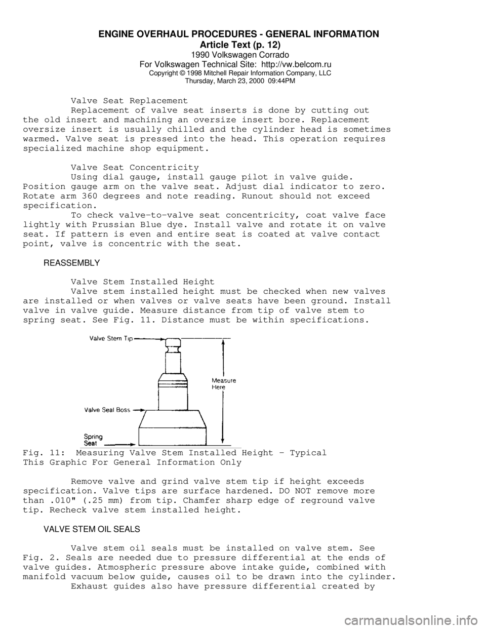
valve in valve guide. Measure distance from tip of valve stem to
spring seat. See Fig. 11. Distance must be within specifications.Fig. 11: Measuring Valve Stem Installed Height - Typical
This Graphic For General Information Only
Remove valve and grind valve stem tip if height exceeds
specification. Valve tips are surface hardened. DO NOT remove more
than .010" (.25 mm) from tip. Chamfer sharp edge of reground valve
tip. Recheck valve stem installed height.
VALVE STEM OIL SEALS
Valve stem oil seals must be installed on valve stem. See
Fig. 2. Seals are needed due to pressure differential at the ends of
valve guides. Atmospheric pressure above intake guide, combined with
manifold vacuum below guide, causes oil to be drawn into the cylinder.
Exhaust guides also have pressure differential created by
Page 646 of 906
MAINTENANCE INFORMATION
Article Text (p. 11)
1990 Volkswagen Corrado
For Volkswagen Technical Site: http://vw.belcom.ru
Copyright © 1998 Mitchell Repair Information Company, LLC
Thursday, March 23, 2000 09:48PM
Application Quantity (1)
A/C System R-12 Refrigerant
1990-92 (up to 7/92) ............................. 37-40 Ozs.
A/C System R-134a Refrigerant (2)
1993-94 (from 7/92) ........................... 28.2-31.8 Ozs.
Cooling System
4-Cyl. ...................................... 6.8 Qts. (6.5L)
V6 .......................................... 9.1 Qts. (8.6L)
Engine Oil (3)
4-Cyl. ...................................... 4.3 Qts. (4.0L)
V6 .......................................... 6.3 Qts. (6.0L)
Fuel Tank
4-Cyl. ..................................... 14.5 Gals. (55L)
V6 ......................................... 18.5 Gals. (55L)
Automatic Transmission
Fluid Change ................................ 3.2 Qts. (3.0L)
Overhaul .................................... 5.9 Qts. (5.6L)
Manual Transmission ........................... 2.1 Qts. (2.0L)
Final Drive
Differential (A/T) (4) ....................... 0.8 Qt. (.75L)
(1) - Capacities are recommended or calculated levels. Always use
dipstick (if available) to measure level.
(2) - Use of R-12 in a R134a system will result in SEVERE DAMAGE.
(3) - Includes oil filter change.
(4) - Lifetime fill.ÄÄÄÄÄÄÄÄÄÄÄÄÄÄÄÄÄÄÄÄÄÄÄÄÄÄÄÄÄÄÄÄÄÄÄÄÄÄÄÄÄÄÄÄÄÄÄÄÄÄÄÄÄÄÄÄÄÄÄÄÄÄÄÄÄ WHEEL & TIRE SPECIFICATIONS
Wheel and tire sizes vary according to vehicle and equipment
and can be found on tire information label on each vehicle. Wheel and
tire specifications and tire inflation pressures are listed on a label
found inside fuel tank flap.
NOTE: Snow chains must be used on drive wheels, in pairs only.
WHEEL TIGHTENING
Tighten all wheel lugs to 80 ft. lbs. (110 N.m).
BATTERY SPECIFICATIONS
CAUTION: When battery is disconnected, vehicles equipped with
computers may lose memory data. When battery power is
restored, driveability problems may exist on some vehicles.
These vehicles may require a relearn procedure. See COMPUTER
RELEARN PROCEDURES article in the GENERAL INFORMATION
section.
All models use BCI group 41 batteries with cold crank rating
Page 678 of 906
N - REMOVE/INSTALL/OVERHAUL
Article Text (p. 5)
1990 Volkswagen Corrado
For Volkswagen Technical Site: http://vw.belcom.ru
Copyright © 1998 Mitchell Repair Information Company, LLC
Thursday, March 23, 2000 09:49PM
distributor. Install fuel distributor. See TORQUE SPECIFICATIONS for
tightening specifications. Connect all fuel lines except those to fuel
injectors. Check sensor plate adjusting lever and fuel distributor
control piston for smooth operation.
2) Remove fuel pump relay and bridge fuel pump circuit. Use
Jumper Switch (US 4480/3) in place of fuel pump relay. When pressure
has built up, turn off fuel pump. Move sensor plate from rest position
to end of travel.
3) Uniform resistance should be felt during entire movement.
No resistance should be felt during entire movement. No resistance
should be felt on quick return to rest position. Connect injector
lines. Install fuel pump relay. Start engine and check for leaks.
INJECTORS (DIGIFANT)
CAUTION: Fuel system pressure must be relieved before removing
injectors. Wipe up all spilled fuel BEFORE continuing
service.
Removal (AFC-Digifant II)
Disconnect negative battery cable. Disconnect main electrical
connector from fuel rail. Remove idle stabilizer valve. Loosen and
remove both hoses on each end of fuel rail. Remove fuel pressure
regulator and mounting bracket. Remove fuel rail mounting bolts. Pry
off injector mounting clips. Disconnect injector electrical
connectors. Remove fuel rail. Remove each injector from its insert.
Installation
To install injectors, reverse removal procedures. Use new "O"
rings when installing injectors. Replace hose clamps if necessary. See
TORQUE SPECIFICATIONS table at end of this article. Check for fuel
leaks.
INJECTORS (CIS SYSTEMS)
Removal (CIS-E & CIS-E Motronic)
Remove injectors from inserts in cylinder head with fuel
lines attached. Using 12-mm or 13-mm hex wrench, remove inserts from
head. Use 2 wrenches to remove injectors from fuel lines.
Installation
To install, reverse removal procedures. Use 2 wrenches when
tightening injector lines to injectors. Use new "O" rings lightly
lubricated. On models with 2-piece inserts, replace insert sealing
washer (against head) and use sealing compound on upper insert
threaded portion. See TORQUE SPECIFICATIONS.
OXYGEN (O2) SENSOR
Removal & Installation
Oxygen (O2) sensor is mounted in the exhaust pipe in front of
catalytic converter. Disconnect permanent pigtail from sensor. Ensure
Page 685 of 906
SCHEDULED SERVICES
Article Text (p. 2)
1990 Volkswagen Corrado
For Volkswagen Technical Site: http://vw.belcom.ru
Copyright © 1998 Mitchell Repair Information Company, LLC
Thursday, March 23, 2000 09:49PM
SUPPLEMENTAL RESTRAINT SYSTEM (SRS) AIR BAR WARNING
NOTE: For information on air bag DIAGNOSIS & TESTING or DISPOSAL
PROCEDURES, see AIR BAGS article in the ACCESSORIES/SAFETY
EQUIPMENT Section.
System circuit is grounded by 2 screws beneath the driver's
seat. DO NOT use these screws to ground any other accessory. DO NOT
ground any other components near this system.
AIR CONDITIONING SERVICING (1993 & LATER)
CAUTION: Avoid breathing R-134a refrigerant and PAG lubricant vapors,
exposure may irritate eyes, nose and throat. To remove
R-134a from system use R-134a recycling equipment that meets
SAE J2210 specifications. If accidental system discharge
occurs, ventilate work area before resuming service.
WARNING: R-134a service equipment or vehicle A/C systems SHOULD NOT
be pressure tested or leak tested with compressed air. Some
mixtures of air/R134a have shown to be combustible at
elevated pressures. These mixtures are dangerous and may
cause fire and/or explosions. See AIR CONDITIONING SERVICE
article in GENERAL INFORMATION section.
ANTI-LOCK BRAKE SYSTEM
The anti-lock brake system contains electronic equipment that
can be susceptible to interference caused by improperly installed or
high output radio transmitting equipment. Since this interference
could cause the possible loss of the anti-lock braking capability,
such equipment should be installed by qualified professionals.
On models equipped with anti-lock brake systems, ALWAYS
observe the following cautions:
* DO NOT attempt to bleed hydraulic system without first
referring to the appropriate ANTI-LOCK BRAKE SYSTEM article
in the BRAKES Section.
* DO NOT mix tire sizes. As long as tires remain close to the
original diameter, increasing the width is acceptable.
Rolling diameter must be identical for all 4 tires. Some
manufacturers recommend tires of the same brand, style and
type. Failure to follow this precaution may cause inaccurate
wheel speed readings.
* Use ONLY recommended brake fluids. DO NOT use silicone brake
fluids in an ABS-equipped vehicle.
BATTERY WARNING
WARNING: When battery is disconnected, vehicles equipped with
computers may lose memory data. When battery power is