cooling VOLKSWAGEN CORRADO 1990 Owner's Manual
[x] Cancel search | Manufacturer: VOLKSWAGEN, Model Year: 1990, Model line: CORRADO, Model: VOLKSWAGEN CORRADO 1990Pages: 906, PDF Size: 6.56 MB
Page 359 of 906

A/C-HEATER SYSTEM - MANUAL
Article Text (p. 2)
1990 Volkswagen Corrado
For Volkswagen Technical Site: http://vw.belcom.ru
Copyright © 1998 Mitchell Repair Information Company, LLC
Thursday, March 23, 2000 09:41PM
Temperature Control Lever
The temperature control lever controls heating and cooling.
When moved to the left, lever turns compressor on. When moved to the
right, a heater water valve is opened, supplying coolant to heater
core.
HIGH-PRESSURE SWITCH
High-pressure switch shuts compressor off if high pressure
reaches 210 psi (14.8 kg/cmý). High-pressure switch will reset when
pressure decreases to 174 psi (12.2 kg/cm
ý).
LOW-PRESSURE SWITCH
Low-pressure switch cuts off system operation when there is
abnormally low pressure in system. This protects the compressor when
there is not enough R-12 in system. Low-pressure switch shuts
compressor off at 26 psi (1.8 kg/cm
ý).
THERMOSWITCH
Thermoswitch shuts compressor off if coolant temperature
rises above 248
øF (120øC).Fig. 1: Locating A/C Components (Vanagon)
Courtesy of Volkswagen United States, Inc.
Page 362 of 906
A/C-HEATER SYSTEM - MANUAL
Article Text (p. 5)
1990 Volkswagen Corrado
For Volkswagen Technical Site: http://vw.belcom.ru
Copyright © 1998 Mitchell Repair Information Company, LLC
Thursday, March 23, 2000 09:41PM
MICROSWITCH
Loosen microswitch mounting screw. Move microswitch so switch
is on when lever is at maximum A/C, NORM (normal), BI-LEVEL or extreme
right position, and off when lever is at VENT or HEAT position.
Tighten microswitch mounting screw. Recheck operation.
TEMPERATURE SWITCH
Move temperature lever to full cool position. Loosen
temperature switch mounting screw. Move temperature switch
counterclockwise to full stop position. Tighten temperature switch
mounting screw.
TROUBLE SHOOTING
NO COOLING
1) Ensure fan motor operates in all 4 speeds, air duct closes
off outside air and heater water valve is closed. Adjust belt tension.
2) Inspect receiver-drier pressure seal. If seal is good, go
to step 5). If seal is broken, evacuate and recharge system. If system
cools properly, testing is complete. If system does not cool, connect
pressure gauges.
3) Set engine speed at 2500 RPM. Insert thermometer in left
register and close all others. Place controls on high blower and
maximum cooling. With vehicle out of direct sunlight, close all
windows. Radiator fan should come on with system pressure at 200 psi
(14 kg/cmý).
NOTE: If system doors allow air leaks, evaporator will freeze up
and testing will not be possible.
4) If fan does not operate, replace pressure switch. Ensure
system is okay. If fan does come on, turn engine off and check for
condenser obstructions and blocked airflow.
5) Turn air conditioner on and off with temperature control
lever. Ensure compressor clutch engages. Push lever to extreme right
position and back again. A click should be heard from compressor
clutch. If a click is not heard, check for voltage at clutch coil wire
with switch on. If voltage is present, replace clutch coil. If voltage
is not present, check wiring or replace thermostatic switch.
6) If compressor clutch operates, check gauge readings. If
both are low, locate leak and recharge system. If both are high,
replace expansion valve. If low side is too high and high side reads
too low, replace or rebuild compressor.
INSUFFICIENT COOLING
1) Ensure fan motor operates at all 4 speeds, air duct closes
off outside air intake and heater water valve is closed. Adjust
compressor belt tension and clean condenser.
Page 363 of 906

A/C-HEATER SYSTEM - MANUAL
Article Text (p. 6)
1990 Volkswagen Corrado
For Volkswagen Technical Site: http://vw.belcom.ru
Copyright © 1998 Mitchell Repair Information Company, LLC
Thursday, March 23, 2000 09:41PM
NOTE: If system doors allow air leaks, evaporator will freeze up
and testing will not be possible.
2) Adjust engine speed to 2500 RPM. Position controls for
maximum cooling and high blower. Insert thermometer in left register
and close all other ducts. With vehicle out of sun, close all windows
and doors. Connect pressure gauges and check readings.
3) If both gauges read too high, replace expansion valve. If
both read too low, recharge system after locating leak. If both
readings are normal, go to next step. If pressure side is too high and
suction side is normal, go to step 5). If pressure side is too low and
suction side is too high, go to step 6). If pressure side is normal
and suction side is too low, go to step 7).
4) Turn compressor off and observe gauges. If readings
equalize in 30 seconds, replace compressor. If readings take longer to
equalize, ensure capillary installation in evaporator is 7" (178 mm)
long on all models.
5) If installation is correct, run system at maximum cooling
for 15 minutes. If thermometer indicates temperature below 36øF (2øC)
when compressor is turned off, or temperature is above 48
øF (9øC) with
compressor on, replace temperature switch.
6) Check condenser fins and clean or straighten. If operation
is still not correct, discharge system, using approved refrigerant
recovery/recycling equipment, until bubbles show in sight glass.
Recharge until bubbles disappear, and recheck pressures. If still
incorrect, locate leaks and tighten fittings. Discharge system using
approved refrigerant recovery/recycling equipment. Evacuate to remove
all air and recharge system.
7) Check for bubbles at sight glass. If present, repair leaks
and recharge system. If no bubbles are present, check condenser-to-
expansion valve line for kinks and repair if necessary. Feel along
line from condenser to expansion valve. If there are no cold spots,
replace expansion valve.
8) If cold spot is felt, remove and flush out lines and
condenser. Check for bubbles at sight glass. If there are no bubbles
present, replace compressor. If bubbles are present, check for leaks.
Repair and recharge system.
INTERMITTENT COOLING
1) Ensure fan motor operates in all 4 speeds, air duct closes
off outside air and heater water valve is closed. Adjust belt tension
and clean condenser.
NOTE: If system doors allow air to leak by, evaporator will freeze
up and testing will no longer be possible.
2) Adjust engine speed to 2500 RPM. Set controls for maximum
cooling and high fan. Insert thermometer in left air duct and close
all other ducts. With vehicle under shade, close windows and doors and
connect pressure gauges. Operate system for 10 minutes.
Page 429 of 906

C - SPECIFICATIONS
Article Text
1990 Volkswagen Corrado
For Volkswagen Technical Site: http://vw.belcom.ru
Copyright © 1998 Mitchell Repair Information Company, LLC
Thursday, March 23, 2000 09:43PM
ARTICLE BEGINNING
1990 ENGINE PERFORMANCE
Volkswagen C - Specifications
All Models
INTRODUCTION
Use this article to quickly find specifications related to
servicing and on-vehicle adjustments. This is a quick-reference
article for when you are familiar with an adjustment procedure and
only need a specification.
BATTERY SPECIFICATIONS TABLE
BATTERY SPECIFICATIONS TABLEÄÄÄÄÄÄÄÄÄÄÄÄÄÄÄÄÄÄÄÄÄÄÄÄÄÄÄÄÄÄÄÄÄÄÄÄÄÄÄÄÄÄÄÄÄÄÄÄÄÄÄÄÄÄÄApplication Amp Hr. Rating
Cabriolet, Fox, Jetta & Jetta GLi
Without A/C .................................... 54
With A/C ....................................... 63
Corrado .......................................... 63
Golf GL/GTI 1.8L, & Vanagon ...................... 63
ÄÄÄÄÄÄÄÄÄÄÄÄÄÄÄÄÄÄÄÄÄÄÄÄÄÄÄÄÄÄÄÄÄÄÄÄÄÄÄÄÄÄÄÄÄÄÄÄÄÄÄÄÄÄÄ FLUID CAPACITIES TABLE
FLUID CAPACITIES TABLE
ÄÄÄÄÄÄÄÄÄÄÄÄÄÄÄÄÄÄÄÄÄÄÄÄÄÄÄÄÄÄÄÄÄÄÄÄÄÄÄÄÄÄÄÄÄÄÄÄÄÄÄÄÄÄÄÄÄÄÄÄÄÄÄÄÄApplication Quantity
Qts. (L)
Auto. Transaxle (Dexron-II) ..................... (1) 3.2 (3.0)
Auto. Transaxle Final Drive (SAE 90/API GL-5)
Except Vanagon ..................................... .8 (.76)
Vanagon ........................................... 1.4 (1.3)
Cooling System (Includes Heater)
Cabriolet ......................................... 5.1 (4.8)
Corrado ........................................... 6.0 (5.5)
Fox ............................................... 6.9 (6.5)
Golf GL/GTI (1.8L) ................................ 7.3 (7.0)
Jetta GLi (2.0L) .................................. 5.1 (4.8)
Jetta ............................................. 5.1 (4.8)
Vanagon ......................................... 18.4 (17.5)
Crankcase (Includes Filter)
Fox ............................................... 3.7 (3.5)
Vanagon ........................................... 4.8 (4.5)
Page 436 of 906

COMPUTER RELEARN PROCEDURES
Article Text
1990 Volkswagen Corrado
For Volkswagen Technical Site: http://vw.belcom.ru
Copyright © 1998 Mitchell Repair Information Company, LLC
Thursday, March 23, 2000 09:43PM
ARTICLE BEGINNING
GENERAL INFORMATION
Computer Relearn Procedures
All Models
* PLEASE READ THIS FIRST *
The following general procedures are to be used if
driveability problems are encountered after power loss or battery has
been disconnected. These procedures may provide an aid in eliminating
these problems.
To reduce the possibility of complaints, after any service
which requires battery power to be disconnected, vehicle should be
road tested.
COMPUTER RELEARN PROCEDURES
Vehicles equipped with engine or transmission computers may
require a relearn procedure after vehicle battery is disconnected.
Many vehicle computers memorize and store vehicle operation patterns
for optimum driveability and performance. When vehicle battery is
disconnected, this memory is lost. The computer will use default data
until new data from each key start is stored. As computer memorizes
vehicle operation for each new key start, driveability is restored.
Vehicle computers may memorize vehicles operation patterns for 40 of
more key starts.
Customers often complain of driveability problems during
relearn stage because vehicle acts differently then before being
serviced. Depending on type and make of vehicle and how it is
equipped, the following complaints (driveability problems) may exist:
* Harsh Or Poor Shift Quality
* Rough Or Unstable Idle
* Hesitation Or Stumble
* Rich Or Lean Running
* Poor Fuel Mileage
These symptoms and complaints should disappear after a number
of drive cycles have been memorized. To reduce the possibility of
complaints, after any service which requires battery power to be
disconnected, vehicle should be road tested. If a specific relearn
procedure is not available, the following procedure may be used:
Automatic Transmission
* Set parking brake, start engine in "P" or "N" position.
Warm-up vehicle to normal operating temperature or until
cooling fan cycles.
* Allow vehicle to idle for one minute in "N" position. Select
Page 438 of 906
D - ADJUSTMENTS
Article Text
1990 Volkswagen Corrado
For Volkswagen Technical Site: http://vw.belcom.ru
Copyright © 1998 Mitchell Repair Information Company, LLC
Thursday, March 23, 2000 09:43PM
ARTICLE BEGINNING
1990 ENGINE PERFORMANCE
On-Vehicle Adjustments
Volkswagen; Cabriolet, Corrado, Fox, Golf GL/GTI,
Jetta, Vanagon
ENGINE COMPRESSION
Check engine compression with engine at normal operating
temperature at specified cranking speed, all spark plugs removed and
throttle wide open.
ENGINE COMPRESSION TESTÄÄÄÄÄÄÄÄÄÄÄÄÄÄÄÄÄÄÄÄÄÄÄÄÄÄÄÄÄÄÄÄÄÄÄÄÄÄÄÄÄÄÄÄÄÄÄÄÄÄÄÄÄÄÄÄÄÄÄÄÄÄÄÄÄÄÄÄÄÄModel Standard Minimum
psi (kg/cm
ý) psi (kg/cmý)
Cabriolet ............. 131-174 (9.0-12.0) ............. 109 (7.5)
Corrado ............... 116-174 (8.0-12.0) .............. 87 (6.0)
Fox ................... 131-174 (9.0-12.0) ............. 102 (7.0)
Golf GL/GTI 1.8L ...... 131-174 (9.0-12.0) ............. 102 (7.0)
Jetta ................. 131-174 (9.0-12.0) ............. 102 (7.0)
Jetta GLi 2.0L ........ 145-190 (10.0-13.0) ............ 109 (7.5)
Vanagon ............... 87-131 (6.1-9.2) ................ 87 (6.0)
ÄÄÄÄÄÄÄÄÄÄÄÄÄÄÄÄÄÄÄÄÄÄÄÄÄÄÄÄÄÄÄÄÄÄÄÄÄÄÄÄÄÄÄÄÄÄÄÄÄÄÄÄÄÄÄÄÄÄÄÄÄÄÄÄÄÄÄÄÄÄ VALVE CLEARANCE
NOTE: All models use hydraulic lifters. No adjustments are
required.
IGNITION TIMING
NOTE: Basic timing readings are only valid when engine idle speed
and idle mixture are within specifications. For best
results, the manufacturer recommends ignition timing, idle
CO and idle speed be checked and adjusted in that order.
NOTE: Off idle timing is computer controlled on models with knock
sensor(s). Only idle ignition timing can be set.
ALL MODELS EXCEPT VANAGON
1) Warm engine to normal operating temperature (cooling fan
should cycle at least once). Remove the 27 mm plastic plug from timing
check hole on transaxle bellhousing.
2) With ignition off, connect a tachometer and timing light
to vehicle. Start engine, raise speed above 2100 RPM a few times, and
allow engine to idle normally. With distributor vacuum hoses
Page 459 of 906
E - THEORY/OPERATION - DIGIFANT
Article Text (p. 9)
1990 Volkswagen Corrado
For Volkswagen Technical Site: http://vw.belcom.ru
Copyright © 1998 Mitchell Repair Information Company, LLC
Thursday, March 23, 2000 09:43PM
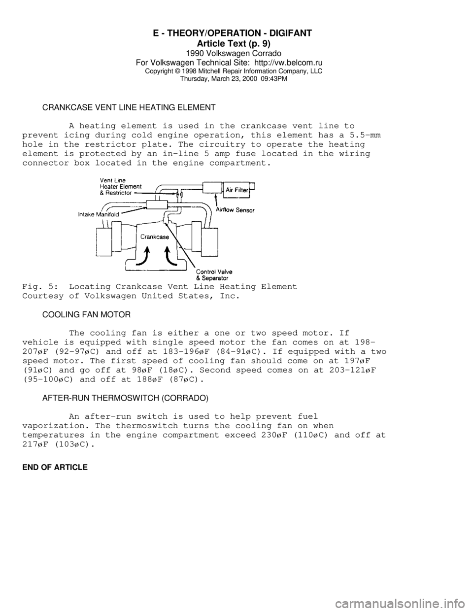
CRANKCASE VENT LINE HEATING ELEMENT
A heating element is used in the crankcase vent line to
prevent icing during cold engine operation, this element has a 5.5-mm
hole in the restrictor plate. The circuitry to operate the heating
element is protected by an in-line 5 amp fuse located in the wiring
connector box located in the engine compartment.Fig. 5: Locating Crankcase Vent Line Heating Element
Courtesy of Volkswagen United States, Inc.
COOLING FAN MOTOR
The cooling fan is either a one or two speed motor. If
vehicle is equipped with single speed motor the fan comes on at 198-
207øF (92-97øC) and off at 183-196øF (84-91øC). If equipped with a two
speed motor. The first speed of cooling fan should come on at 197
øF
(91
øC) and go off at 98øF (18øC). Second speed comes on at 203-121øF
(95-100
øC) and off at 188øF (87øC).
AFTER-RUN THERMOSWITCH (CORRADO)
An after-run switch is used to help prevent fuel
vaporization. The thermoswitch turns the cooling fan on when
temperatures in the engine compartment exceed 230
øF (110øC) and off at
217
øF (103øC).
END OF ARTICLE
Page 565 of 906
FUSES & CIRCUIT BREAKERS
Article Text (p. 3)
1990 Volkswagen Corrado
For Volkswagen Technical Site: http://vw.belcom.ru
Copyright © 1998 Mitchell Repair Information Company, LLC
Thursday, March 23, 2000 09:45PM
start at any time even when the ignition key is in the OFF
position. DO NOT loosen or remove radiator cap when cooling
system is hot.
REPLACING BLOWN FUSES
Before replacing a blown fuse, remove ignition key, turn off
all lights and accessories to avoid damaging the electrical system. Be
sure to use fuse with the correct indicated amperage rating. The use
of an incorrect amperage rating fuse may result in a dangerous
electrical system overload.
BATTERY WARNING
WARNING: When battery is disconnected, vehicles equipped with
computers may lose memory data. When battery power is
restored, driveability problems may exist on some vehicles.
These vehicles may require a relearn procedure. See COMPUTER
RELEARN PROCEDURES article in GENERAL INFORMATION section.
BRAKE PAD WEAR INDICATOR
Indicator will cause a squealing or scraping noise, warning
that brake pads need replacement.
HALOGEN BULBS
Halogen bulbs contain pressurized gas which may explode if
overheated. DO NOT touch glass portion of bulb with bare hands. Eye
protection should be worn when handling or working around halogen
bulbs.
SUPPLEMENTAL RESTRAINT SYSTEM (AIR BAG)
NOTE: See the AIR BAGS article in the ACCESSORIES/SAFETY EQUIPMENT
Section.
Modifications or improper maintenance, including incorrect
removal and installation of the Supplemental Restraint System (SRS),
can adversely affect system performance. DO NOT cover, obstruct or
change the steering wheel horn pad in any way, as such action could
cause improper function of the system. Use only plain water when
cleaning the horn pad. Solvents or cleaners could adversely affect the
air bag cover and cause improper deployment of the system.
WARNING: To avoid injury from accidental air bag deployment, read and
carefully follow all warnings and service precautions. See
appropriate AIR BAGS article in ACCESSORIES/SAFETY EQUIPMENT.
CAUTION: Disconnect negative battery cable before servicing any air
bag system, steering column or passenger side dash
component. After any repair, turn ignition key to the ON
Page 571 of 906

GENERAL COOLING SYSTEM SERVICING
Article Text
1990 Volkswagen Corrado
For Volkswagen Technical Site: http://vw.belcom.ru
Copyright © 1998 Mitchell Repair Information Company, LLC
Thursday, March 23, 2000 09:45PM
ARTICLE BEGINNING
GENERAL INFORMATION
General Cooling System Servicing
* PLEASE READ THIS FIRST *
The following article is for general information only.
Information may not apply to all years, makes and models. See specific
article in the ENGINE COOLING section.
DESCRIPTION
The basic liquid cooling system consists of a radiator, water
pump, thermostat, electric or belt-driven cooling fan, pressure cap,
heater, and various connecting hoses and cooling passages in the block
and cylinder head.
MAINTENANCE
DRAINING
Remove radiator cap and open heater control valve to maximum
heat position. Open drain cocks or remove plugs in bottom of radiator
and engine block. In-line engines usually have one plug or drain cock,
while "V" type engines will have 2, one in each bank of cylinders.
CLEANING
A good cleaning compound removes most rust and scale. Follow
manufacturer's instructions in the use of cleaner. If considerable
rust and scale has to be removed, cooling system should be flushed.
Clean radiator air passages with compressed air.
FLUSHING
CAUTION: Some manufacturers use an aluminum and plastic radiator.
Flushing solution must be compatible with aluminum.
Back Flushing
Back flushing is an effective means of removing cooling
system rust and scale. The radiator, engine and heater core should be
flushed separately.
Radiator
To flush radiator, connect flushing gun to water outlet of
radiator and disconnect water inlet hose. To prevent flooding engine,
use a hose connected to radiator inlet. Use air in short bursts to
prevent damage to radiator. Continue flushing until water runs clear.
Engine
Page 572 of 906
GENERAL COOLING SYSTEM SERVICING
Article Text (p. 2)
1990 Volkswagen Corrado
For Volkswagen Technical Site: http://vw.belcom.ru
Copyright © 1998 Mitchell Repair Information Company, LLC
Thursday, March 23, 2000 09:45PM
To flush engine, remove thermostat and replace housing.
Connect flushing gun to water outlet of engine. Flush using short air
bursts until water runs clean.
Heater Core
Flush heater core as described for radiator. Ensure heater
control valve is set to maximum heat position before flushing heater.
REFILLING
To prevent air from being trapped in engine block, engine
should be running when refilling cooling system. After system is full,
continue running engine until thermostat is open, then recheck fill
level. Do not overfill system.
TESTING
THERMOSTAT
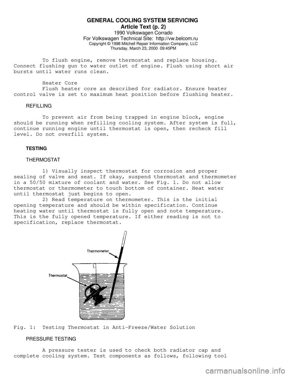
1) Visually inspect thermostat for corrosion and proper
sealing of valve and seat. If okay, suspend thermostat and thermometer
in a 50/50 mixture of coolant and water. See Fig. 1. Do not allow
thermostat or thermometer to touch bottom of container. Heat water
until thermostat just begins to open.
2) Read temperature on thermometer. This is the initial
opening temperature and should be within specification. Continue
heating water until thermostat is fully open and note temperature.
This is the fully opened temperature. If either reading is not to
specification, replace thermostat.Fig. 1: Testing Thermostat in Anti-Freeze/Water Solution
PRESSURE TESTING
A pressure tester is used to check both radiator cap and
complete cooling system. Test components as follows, following tool