battery VOLKSWAGEN CORRADO 1990 Service Manual
[x] Cancel search | Manufacturer: VOLKSWAGEN, Model Year: 1990, Model line: CORRADO, Model: VOLKSWAGEN CORRADO 1990Pages: 906, PDF Size: 6.56 MB
Page 589 of 906
I - SYSTEM/COMPONENT TESTS
Article Text (p. 2)
1990 Volkswagen Corrado
For Volkswagen Technical Site: http://vw.belcom.ru
Copyright © 1998 Mitchell Repair Information Company, LLC
Thursday, March 23, 2000 09:46PMÄÄÄÄÄÄÄÄÄÄÄÄÄÄÄÄÄÄÄÄÄÄÄÄÄÄÄÄÄÄÄÄÄÄÄÄÄÄÄÄÄÄÄÄÄÄÄÄÄÄÄÄÄÄÄÄÄÄÄÄÄÄÄÄÄÄÄÄÄÄ CONTROL UNIT (AFC-DIGIFANT II)
NOTE: Before checking ECU terminal voltages, check all terminals
and connections for looseness or presence of corrosion.
Repair as needed, before continuing.
GROUND CIRCUITS
Using Multimeter (US 1119), check resistance of ground
connections for ECU. Remove ECU connector. Check continuity to ground
on terminals No. 13 and 19. See L - WIRING DIAGRAMS for terminal
identification. Resistance should be zero ohms. If resistance is not
zero ohms, repair open or short in wiring.
POWER CIRCUITS
1) Turn ignition off. Disconnect ECU connector. Using a
voltmeter, turn ignition on and check for battery voltage between ECU
connector terminals No. 13 (negative) and No. 14 (positive). See L -
WIRING DIAGRAMS for terminal identification and wire colors. If
battery voltage is not present, repair wiring as required.
2) Check terminals No. 13 (negative) and No. 1 (positive) for
battery voltage. If battery voltage is not present, check fuse No. 18
on fuse block. If fuse is okay, check wiring from ECU connector to
fuse box for open.
CONTROL UNIT (CIS-E)
GROUND CIRCUITS
Using Multimeter (US 1119), check resistance of ground
circuits for ECU. Remove ECU connector. Check continuity to ground on
terminals No. 2 and No. 9. Resistance should be zero ohms. If
resistance is not zero ohms, repair open or short in wiring.
POWER CIRCUITS
Turn ignition off. Disconnect ECU connector. Using a
voltmeter, turn ignition on and check for battery voltage between ECU
connector terminals No. 2 (negative) and No. 1 (positive). See L -
WIRING DIAGRAMS for terminal identification and wire colors. If
battery voltage is not present, check fuse No. 23 on fuse block. If
fuse is okay, check CIS-E ECU connector to fuse box wiring for open.
CONTROL UNIT (CIS-MOTRONIC)
GROUND CIRCUITS
Using Multimeter (US 1119), check resistance of ground
Page 590 of 906
I - SYSTEM/COMPONENT TESTS
Article Text (p. 3)
1990 Volkswagen Corrado
For Volkswagen Technical Site: http://vw.belcom.ru
Copyright © 1998 Mitchell Repair Information Company, LLC
Thursday, March 23, 2000 09:46PM
circuits to ECU. The ECU engine ground is near ignition distributor.
Remove ECU connector. Check resistance to ground on terminal No. 35.
Resistance should be zero ohms. If resistance is not zero ohms, repair
open or short in wiring.
POWER CIRCUITS
Turn ignition off. Disconnect ECU connector. Using a
voltmeter, check terminals No. 12, 14, 19 and 34 for battery voltage.
If battery voltage is not present. Check fuses No. 15, 18 and 24. If
fuses are okay, check for open in wiring between ECU and fuse box. See
L - WIRING DIAGRAMS for terminal identification and wire colors.
ENGINE SENSORS & SWITCHES
AIRFLOW SENSOR (FOX & JETTA GLI)
1) Start engine to pressurized fuel system. Turn engine off
and remove intake boot from top of airflow sensor. Disconnect coil
secondary wire from coil and jumper to ground.
2) Check sensor play by slowly moving sensor plate through
travel range with a magnet. See Fig. 1. Resistance should be felt.
Move plate back to the rest position. There should be no resistance.
If binding is felt, loosen sensor plate hold-down bolt and adjust
plate to center of venturi.
3) If resistance is uneven, remove airflow sensor from
housing to clean and lubricate lever assembly. If resistance is caused
by control plunger, remove and clean control plunger assembly. If
binding continues, replace fuel distributor.
4) Check position of airflow sensor plate. Airflow sensor
plate edge must be within .075" (1.9 mm) below the narrowest section
of the venturi. If not, bend sensor spring until correct specification
is obtained. Ensure a small gap exists between sensor lever and
control plunger.Fig. 1: Identifying Airflow Sensor Components (Fox & Jetta GLi)
Courtesy of Volkswagen United States, Inc.
AIRFLOW SENSOR (GOLF & JETTA)
1) Start engine to pressurized fuel system. Turn engine off
Page 594 of 906
I - SYSTEM/COMPONENT TESTS
Article Text (p. 7)
1990 Volkswagen Corrado
For Volkswagen Technical Site: http://vw.belcom.ru
Copyright © 1998 Mitchell Repair Information Company, LLC
Thursday, March 23, 2000 09:46PM
1) Disconnect throttle valve switch connector. With ohmmeter
set on 200-ohm scale, attach probes to male terminals. Ensure throttle
valve switch is completely closed. With throttle valve closed, meter
reading should be zero.
2) Position throttle valve to 1/2 open position. Ohmmeter
reading should be infinite. Position throttle to fully open position.
Ohmmeter reading should be zero. If any reading is incorrect, perform
throttle valve switch adjustment. See D - ADJUSTMENTS article.
3) If correct specifications cannot be obtained, check
throttle shaft play, accelerator cable adjustment and throttle switch
actuating cam. If okay, replace throttle valve switch.
RELAYS
FUEL PUMP RELAY (CABRIOLET, GOLF GL/GTI & JETTA)
1) Ensure fuel pump fuse (No. 5) is okay. Remove fuel pump
relay (No. 2) from fuse/relay panel. See Fig. 6. With ignition on,
check for battery voltage between the following locations:
* Terminal No. 2 and ground
* Terminals No. 2 and No. 1
* Terminal No. 4 and No. 1
If voltage is not present, repair wiring and recheck fuel
pump operation.
2) With battery voltage present between terminal No. 1 and
terminal No. 5, lightly touch middle wire of ignition distributor
harness connector to ground. If voltage drops, replace fuel pump relay
and check Hall Effect sender.
3) If voltage does not drop, check Hall Effect sender. See
HALL EFFECT SENDER in F - BASIC TESTING ARTICLE. For fuel pump and
fuse number/location, see FUEL PUMP RELAY & FUSE NUMBER TABLE.Fig. 6: Identifying Fuse/Relay Panel (All Models Except Vanagon)
Courtesy of Volkswagen United States, Inc.
Page 595 of 906
I - SYSTEM/COMPONENT TESTS
Article Text (p. 8)
1990 Volkswagen Corrado
For Volkswagen Technical Site: http://vw.belcom.ru
Copyright © 1998 Mitchell Repair Information Company, LLC
Thursday, March 23, 2000 09:46PM
FUEL PUMP RELAY (FOX)
1) Ensure fuel pump fuse (No. 13) is okay. Remove fuel pump
relay. Note terminals numbers molded on fuse/relay panel. With
ignition on, check for battery voltage between the following
locations:
* Terminal No. 46 and ground
* Terminal No. 48 and ground
2) If voltage is not present, current is not reaching the
relay. Repair wiring. Check fuel pump operation. If voltage is
present, check for battery voltage between the following locations:
* Terminals No. 48 and No. 50
* Terminals No. 46 and No. 50
If voltage is not present, terminal No. 50 (ground circuit)
is open. Repair wiring. Check fuel pump operation.
3) If voltage is present, check for battery voltage between
terminals No. 50 and No. 51. If voltage is not present, the ignition
signal is not reaching fuel pump relay. Repair wiring. Check fuel pump
operation.
4) If no faults can be found and fuel pump operates when
relay is by-passed, replace fuel pump relay. For fuel pump and fuse
number/location, see FUEL PUMP RELAY & FUSE NUMBER table.
FUEL PUMP RELAY (CORRADO)
1) Ensure fuel pump fuse No. 18 is okay. Remove fuel pump
relay No. 12 from fuse/relay panel. See Fig. 6. With ignition on,
check for battery voltage between the following locations:
* Terminal No. 6 and ground.
* Terminal No. 2 and ground.
* Terminals No. 6 and No. 4.
2) If battery voltage is not present, check wiring and repair
as needed. Check fuel pump operation. With ignition off, connect
voltmeter between terminals No. 2 and No. 3. Turn ignition on. Voltage
should be present for one second. If voltage is not present for one
second, check wiring to ECU or replace ECU. Check fuel pump relay
operation. For fuel pump and fuse number/location, see FUEL PUMP RELAY
& FUSE NUMBER table.
FUEL PUMP RELAY (VANAGON)
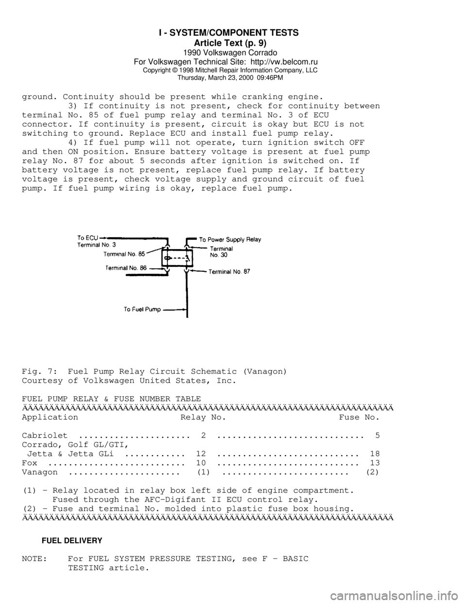
1) Check terminal No. 30 and terminal No. 86 of fuel pump
relay for battery voltage. If battery voltage is not present, check
circuit for short or open circuit.
2) If battery voltage is present, remove relay and attach
ohmmeter probe to relay box terminal No. 85. Attach other probe to
Page 596 of 906
I - SYSTEM/COMPONENT TESTS
Article Text (p. 9)
1990 Volkswagen Corrado
For Volkswagen Technical Site: http://vw.belcom.ru
Copyright © 1998 Mitchell Repair Information Company, LLC
Thursday, March 23, 2000 09:46PM
ground. Continuity should be present while cranking engine.
3) If continuity is not present, check for continuity between
terminal No. 85 of fuel pump relay and terminal No. 3 of ECU
connector. If continuity is present, circuit is okay but ECU is not
switching to ground. Replace ECU and install fuel pump relay.
4) If fuel pump will not operate, turn ignition switch OFF
and then ON position. Ensure battery voltage is present at fuel pump
relay No. 87 for about 5 seconds after ignition is switched on. If
battery voltage is not present, replace fuel pump relay. If battery
voltage is present, check voltage supply and ground circuit of fuel
pump. If fuel pump wiring is okay, replace fuel pump.Fig. 7: Fuel Pump Relay Circuit Schematic (Vanagon)
Courtesy of Volkswagen United States, Inc.
FUEL PUMP RELAY & FUSE NUMBER TABLEÄÄÄÄÄÄÄÄÄÄÄÄÄÄÄÄÄÄÄÄÄÄÄÄÄÄÄÄÄÄÄÄÄÄÄÄÄÄÄÄÄÄÄÄÄÄÄÄÄÄÄÄÄÄÄÄÄÄÄÄÄÄÄÄÄÄÄÄÄÄApplication Relay No. Fuse No.
Cabriolet ...................... 2 ............................. 5
Corrado, Golf GL/GTI,
Jetta & Jetta GLi ............ 12 ............................ 18
Fox ........................... 10 ............................ 13
Vanagon ...................... (1) ......................... (2)
(1) - Relay located in relay box left side of engine compartment.
Fused through the AFC-Digifant II ECU control relay.
(2) - Fuse and terminal No. molded into plastic fuse box housing.
ÄÄÄÄÄÄÄÄÄÄÄÄÄÄÄÄÄÄÄÄÄÄÄÄÄÄÄÄÄÄÄÄÄÄÄÄÄÄÄÄÄÄÄÄÄÄÄÄÄÄÄÄÄÄÄÄÄÄÄÄÄÄÄÄÄÄÄÄÄÄ FUEL DELIVERY
NOTE: For FUEL SYSTEM PRESSURE TESTING, see F - BASIC
TESTING article.
Page 598 of 906
I - SYSTEM/COMPONENT TESTS
Article Text (p. 11)
1990 Volkswagen Corrado
For Volkswagen Technical Site: http://vw.belcom.ru
Copyright © 1998 Mitchell Repair Information Company, LLC
Thursday, March 23, 2000 09:46PM
okay, check ground circuit through thermo time switch. Replace thermo
time switch if contact to ground cannot be made.
IDLE CONTROL SYSTEM
NOTE: Knock control is integral in AFC-Digifant II ECU.
KNOCK SENSOR CONTROL UNIT (ALL MODELS EXCEPT VANAGON)
1) Check ignition coil and Hall Effect sender before checking
knock sensor control unit. Remove knock sensor control unit harness
connector. Turn ignition on. Using a voltmeter, check for battery
voltage between terminals No. 3 and No. 5 and terminals No. 6 and No.
3 of knock sensor control unit. Open throttle valve. Voltage should
drop to zero volts.
2) If voltage does not drop to zero volts, check throttle
valve switch (full throttle). Check voltage between terminals No. 8
and No. 3, while fully opening throttle valve. If battery voltage was
not present when throttle fully open, replace throttle valve switch.
See Fig. 13.
3) Remove Hall Effect sender connector and connect voltmeter
to outside terminals. Turn ignition on. There should be 5 volts
present. Turn ignition off. Connect voltmeter between terminals No. 1
(negative) and No. 15 (positive) of ignition coil. Turn ignition on
and touch center terminal of Hall Effect sender briefly to ground.
Voltage should jump momentarily to approximately 2 volts. If voltage
does not jump, replace knock sensor control unit.
KNOCK SENSOR(S)
Before replacing knock sensor, check knock sensor torque and
resistance. Remove knock sensor connector and check resistance between
terminals No. 13 and No. 14. See KNOCK SENSOR TORQUE & RESISTANCE
SPECIFICATION table. If resistance is incorrect, replace knock sensor.
NOTE: Knock sensor mounting bolt torque must be exact. DO NOT use
washers when mounting knock sensor.
KNOCK SENSOR RESISTANCE & TORQUE SPECIFICATIONÄÄÄÄÄÄÄÄÄÄÄÄÄÄÄÄÄÄÄÄÄÄÄÄÄÄÄÄÄÄÄÄÄÄÄÄÄÄÄÄÄÄÄÄÄÄÄÄÄÄÄÄÄÄÄÄÄÄÄÄÄÄÄÄÄÄÄÄÄÄApplication Resistance Ft. Lbs (N.m)
Type I ...................... 300,000 ................ 7-9 (10-12)
Type II .................... Infinite .............. 15-18 (20-25)
ÄÄÄÄÄÄÄÄÄÄÄÄÄÄÄÄÄÄÄÄÄÄÄÄÄÄÄÄÄÄÄÄÄÄÄÄÄÄÄÄÄÄÄÄÄÄÄÄÄÄÄÄÄÄÄÄÄÄÄÄÄÄÄÄÄÄÄÄÄÄ IDLE STABILIZATION SYSTEM (VANAGON)
1) Attach Test Meter (VW 1315/2) and Adapter (US 1119) to
idle stabilization valve. Set meter to milliampere scale. Start
engine. Observe test meter while turning A/C control switch to ON
position. If milliampere reading increases, system is okay.
Page 605 of 906

INSTRUMENT PANEL
Article Text (p. 3)
1990 Volkswagen Corrado
For Volkswagen Technical Site: http://vw.belcom.ru
Copyright © 1998 Mitchell Repair Information Company, LLC
Thursday, March 23, 2000 09:46PM
Removal & Installation
Disconnect negative battery cable. Remove steering wheel.
Pull tilt shelf downward. Remove 3 shelf retaining screws and remove
shelf. Remove 3 instrument panel lower retaining screws and and pry
off 3 clips. Remove 2 instrument trim retaining screws and remove
instrument panel trim. Remove center instrument cluster screw and tip
instrument panel cluster forward. Remove speedometer cable and wiring
connector from back of cluster. Remove instrument panel cluster. To
install, reverse removal procedure.
INSTRUMENT CLUSTER - FOX
Removal & Installation
Disconnect negative battery cable. Remove steering wheel.
Carefully remove covers from vacant switch position. Depress switch
spring retainer and remove switches from instrument panel. Disconnect
wire connectors from switches. Remove 4 instrument cluster trim
retaining screws. Remove instrument cluster trim panel. Remove 2
instrument cluster retaining screws. Remove speedometer cable.
Disconnect cluster wire connector and remove instrument cluster. To
install, reverse removal procedure.
INSTRUMENT CLUSTER - GOLF, GTI, JETTA & JETTA GLI
Removal & Installation
Remove temperature control knobs, levers and trim plate.
Remove radio or convenience tray. Remove switches from instrument
panel trim plate. Remove instrument panel trim plate. Remove 2
mounting screws and pull instrument cluster outward. Remove
speedometer cable, vacuum hoses, and electrical connections. To
install, reverse removal procedures.
INSTRUMENT CLUSTER - VANAGON
Removal & Installation
Disconnect negative battery cable. Reach behind cluster hood
and pull back of hood upward. Pull hazard switch forward. Pull brake
warning light housing toward front of vehicle. Remove 4 mounting
screws and remove cluster. To install, reverse removal procedure.
COMBINATION SWITCH
Removal
Remove steering wheel. Remove column cover. Disconnect wiring
and remove 3 switch screws. Remove switches.
Installation
Install switches on column. Place steering wheel on column
and ensure clearance between wheel and turn signal switch is 1/16-
1/8". Move spacer sleeve up or down to adjust clearance. Tighten
steering wheel nut to 36 ft. lbs. (50 N.m) and replace pad.
Page 611 of 906
J - PIN VOLTAGE CHARTS
Article Text
1990 Volkswagen Corrado
For Volkswagen Technical Site: http://vw.belcom.ru
Copyright © 1998 Mitchell Repair Information Company, LLC
Thursday, March 23, 2000 09:46PM
ARTICLE BEGINNING
1990 ENGINE PERFORMANCE
Pin Voltage & Sensor Operating Ranges
Volkswagen; Corrado, Fox, Golf, Jetta, Vanagon
NOTE: Cabriolet pin voltage and sensor operating range charts are
not available from manufacturer.
INTRODUCTION
Pin voltage charts are supplied to reduce diagnostic time.
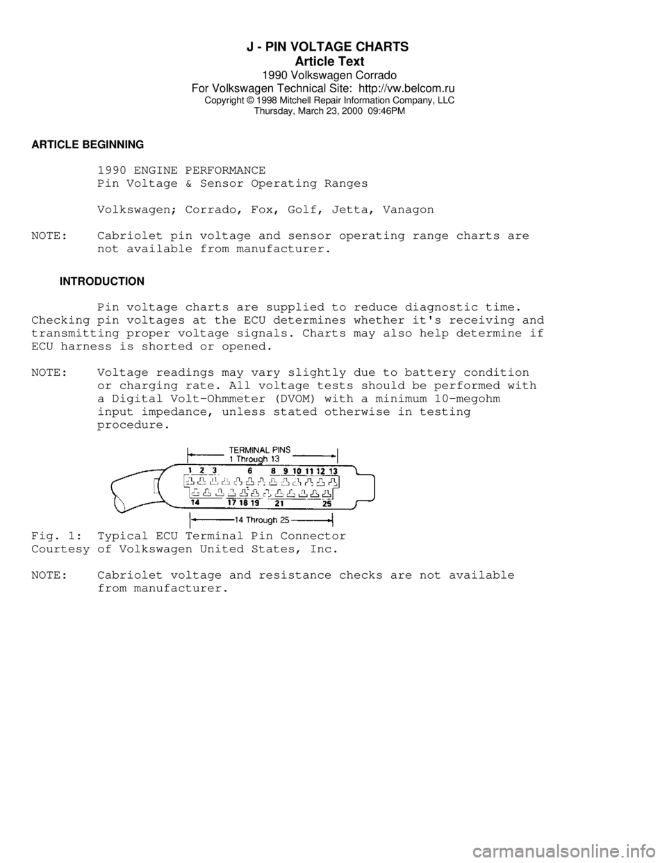
Checking pin voltages at the ECU determines whether it's receiving and
transmitting proper voltage signals. Charts may also help determine if
ECU harness is shorted or opened.
NOTE: Voltage readings may vary slightly due to battery condition
or charging rate. All voltage tests should be performed with
a Digital Volt-Ohmmeter (DVOM) with a minimum 10-megohm
input impedance, unless stated otherwise in testing
procedure.Fig. 1: Typical ECU Terminal Pin Connector
Courtesy of Volkswagen United States, Inc.
NOTE: Cabriolet voltage and resistance checks are not available
from manufacturer.
Page 617 of 906

K - SENSOR RANGE CHARTS
Article Text
1990 Volkswagen Corrado
For Volkswagen Technical Site: http://vw.belcom.ru
Copyright © 1998 Mitchell Repair Information Company, LLC
Thursday, March 23, 2000 09:46PM
ARTICLE BEGINNING
1990 ENGINE PERFORMANCE
Pin Voltage & Sensor Operating Ranges
Volkswagen; Corrado, Fox, Golf, Jetta, Vanagon
NOTE: Cabriolet pin voltage and sensor operating range charts are
not available from manufacturer.
INTRODUCTION
Pin voltage charts are supplied to reduce diagnostic time.
Checking pin voltages at the ECU determines whether it's receiving and
transmitting proper voltage signals. Charts may also help determine if
ECU harness is shorted or opened.
NOTE: Voltage readings may vary slightly due to battery condition
or charging rate. All voltage tests should be performed with
a Digital Volt-Ohmmeter (DVOM) with a minimum 10-megohm
input impedance, unless stated otherwise in testing
procedure.Fig. 1: Typical ECU Terminal Pin Connector
Courtesy of Volkswagen United States, Inc.
NOTE: Cabriolet voltage and resistance checks are not available
from manufacturer.
Page 636 of 906
MAINTENANCE INFORMATION
Article Text
1990 Volkswagen Corrado
For Volkswagen Technical Site: http://vw.belcom.ru
Copyright © 1998 Mitchell Repair Information Company, LLC
Thursday, March 23, 2000 09:48PM
ARTICLE BEGINNING
1990-94 MAINTENANCE
Volkswagen Maintenance Information
Corrado G60 (1990-92)
SLC (1992-94 USA)
VR6 (1992-94 Canada)
* PLEASE READ THIS FIRST *
NOTE: For scheduled maintenance intervals and the related fluid
capacities, fluid specifications and labor times for major
service intervals, see SCHEDULED SERVICES article in this
section. Warranty information and specifications for fluid
capacities, lubrication specifications, wheel and tire size,
and battery type are covered in this article.
MODEL IDENTIFICATION
VIN LOCATION
The Vehicle Identification Number (VIN) is located on the
left side of the dash panel at the base of the windshield. The VIN
chart explains the code characters.
VIN CODE ID EXPLANATION
Numbers preceding the explanations in the legend below refer
to the sequence of characters as listed on VIN identification label.
See VIN example below.ÚÄÄÄÄÄÄÄÄÄÄÄÄÄÄÄÄÄÄÄÄÄÄÄÄÄÄÄÄÄÄÄÄÄÄÄÄÄÄÄÄÄÄÄÄÄÄÄÄÄÄÄÄÄÄÄÄÄÄÄÄÄ¿
³ (VIN) W V W A B 0 5 3 2 M H 0 9 9 7 1 7
³
³ 1 2 3 4 5 6 7 8 9 10 11 12 13 14 15 16 17
³
ÀÄÄÄÄÄÄÄÄÄÄÄÄÄÄÄÄÄÄÄÄÄÄÄÄÄÄÄÄÄÄÄÄÄÄÄÄÄÄÄÄÄÄÄÄÄÄÄÄÄÄÄÄÄÄÄÄÄÄÄÄÄÙ1 - Manufacturing Country
W * Germany
1 * United States
3 * Mexico
9 * Brazil
2-3 - Manufacturer
VW * Volkswagen
4 - Series
D * 2-Door G60 (1990-92)
E * 2-Door SLC (1992-94 USA)
E * 2-Door VR6 (1992-94 Canada)