battery VOLKSWAGEN CORRADO 1990 Owner's Manual
[x] Cancel search | Manufacturer: VOLKSWAGEN, Model Year: 1990, Model line: CORRADO, Model: VOLKSWAGEN CORRADO 1990Pages: 906, PDF Size: 6.56 MB
Page 419 of 906
ANTI-LOCK BRAKE SYSTEM
Article Text (p. 11)
1990 Volkswagen Corrado
For Volkswagen Technical Site: http://vw.belcom.ru
Copyright © 1998 Mitchell Repair Information Company, LLC
Thursday, March 23, 2000 09:42PM
REMOVAL & INSTALLATION
HYDRAULIC MODULATOR/PUMP
Removal & Installation
1) Depressurize brake system. See DEPRESSURIZING BRAKE
SYSTEM. Disconnect negative battery cable. Unplug all electrical
connectors from hydraulic modulator/pump. Identify and disconnect all
hydraulic lines from hydraulic modulator/pump. Plug all line openings.
2) From inside passenger compartment, remove push rod clevis
pin. Remove hydraulic modulator/pump retaining nuts. Remove hydraulic
modulator/pump. To install, reverse removal procedure. Tighten all
fittings to specification. See TORQUE SPECIFICATIONS TABLE at end of
article. Bleed brake system. See BLEEDING BRAKE SYSTEM.
WHEEL SPEED SENSORS
NOTE: To protect magnetic part of sensor, always leave new wheel
speed sensor in special packaging until ready for
installation.
Removal & Installation
Remove bolt retaining wheel speed sensor. Unplug connector.
Remove wheel speed sensor. To install, apply Lubricant (G-000-650) to
sensor. Install sensor, and tighten retaining bolt to 84 INCH lbs. (10
N.m).
TORQUE SPECIFICATIONS
TORQUE SPECIFICATIONS TABLEÄÄÄÄÄÄÄÄÄÄÄÄÄÄÄÄÄÄÄÄÄÄÄÄÄÄÄÄÄÄÄÄÄÄÄÄÄÄÄÄÄÄÄÄÄÄÄÄÄÄÄÄÄÄÄÄÄÄÄÄÄÄÄÄÄApplications Ft. Lbs. (N.m)
Brake Lines-To-Hydraulic Modulator/Pump ............... 11 (15)
Hydraulic Modulator/Pump Retaining Nuts ............... 18 (25)
INCH Lbs. (N.m)
Wheel Sensor Retaining Bolt .......................... 84 (9.5)
ÄÄÄÄÄÄÄÄÄÄÄÄÄÄÄÄÄÄÄÄÄÄÄÄÄÄÄÄÄÄÄÄÄÄÄÄÄÄÄÄÄÄÄÄÄÄÄÄÄÄÄÄÄÄÄÄÄÄÄÄÄÄÄÄÄ WIRING DIAGRAMS
Page 429 of 906

C - SPECIFICATIONS
Article Text
1990 Volkswagen Corrado
For Volkswagen Technical Site: http://vw.belcom.ru
Copyright © 1998 Mitchell Repair Information Company, LLC
Thursday, March 23, 2000 09:43PM
ARTICLE BEGINNING
1990 ENGINE PERFORMANCE
Volkswagen C - Specifications
All Models
INTRODUCTION
Use this article to quickly find specifications related to
servicing and on-vehicle adjustments. This is a quick-reference
article for when you are familiar with an adjustment procedure and
only need a specification.
BATTERY SPECIFICATIONS TABLE
BATTERY SPECIFICATIONS TABLEÄÄÄÄÄÄÄÄÄÄÄÄÄÄÄÄÄÄÄÄÄÄÄÄÄÄÄÄÄÄÄÄÄÄÄÄÄÄÄÄÄÄÄÄÄÄÄÄÄÄÄÄÄÄÄApplication Amp Hr. Rating
Cabriolet, Fox, Jetta & Jetta GLi
Without A/C .................................... 54
With A/C ....................................... 63
Corrado .......................................... 63
Golf GL/GTI 1.8L, & Vanagon ...................... 63
ÄÄÄÄÄÄÄÄÄÄÄÄÄÄÄÄÄÄÄÄÄÄÄÄÄÄÄÄÄÄÄÄÄÄÄÄÄÄÄÄÄÄÄÄÄÄÄÄÄÄÄÄÄÄÄ FLUID CAPACITIES TABLE
FLUID CAPACITIES TABLE
ÄÄÄÄÄÄÄÄÄÄÄÄÄÄÄÄÄÄÄÄÄÄÄÄÄÄÄÄÄÄÄÄÄÄÄÄÄÄÄÄÄÄÄÄÄÄÄÄÄÄÄÄÄÄÄÄÄÄÄÄÄÄÄÄÄApplication Quantity
Qts. (L)
Auto. Transaxle (Dexron-II) ..................... (1) 3.2 (3.0)
Auto. Transaxle Final Drive (SAE 90/API GL-5)
Except Vanagon ..................................... .8 (.76)
Vanagon ........................................... 1.4 (1.3)
Cooling System (Includes Heater)
Cabriolet ......................................... 5.1 (4.8)
Corrado ........................................... 6.0 (5.5)
Fox ............................................... 6.9 (6.5)
Golf GL/GTI (1.8L) ................................ 7.3 (7.0)
Jetta GLi (2.0L) .................................. 5.1 (4.8)
Jetta ............................................. 5.1 (4.8)
Vanagon ......................................... 18.4 (17.5)
Crankcase (Includes Filter)
Fox ............................................... 3.7 (3.5)
Vanagon ........................................... 4.8 (4.5)
Page 436 of 906

COMPUTER RELEARN PROCEDURES
Article Text
1990 Volkswagen Corrado
For Volkswagen Technical Site: http://vw.belcom.ru
Copyright © 1998 Mitchell Repair Information Company, LLC
Thursday, March 23, 2000 09:43PM
ARTICLE BEGINNING
GENERAL INFORMATION
Computer Relearn Procedures
All Models
* PLEASE READ THIS FIRST *
The following general procedures are to be used if
driveability problems are encountered after power loss or battery has
been disconnected. These procedures may provide an aid in eliminating
these problems.
To reduce the possibility of complaints, after any service
which requires battery power to be disconnected, vehicle should be
road tested.
COMPUTER RELEARN PROCEDURES
Vehicles equipped with engine or transmission computers may
require a relearn procedure after vehicle battery is disconnected.
Many vehicle computers memorize and store vehicle operation patterns
for optimum driveability and performance. When vehicle battery is
disconnected, this memory is lost. The computer will use default data
until new data from each key start is stored. As computer memorizes
vehicle operation for each new key start, driveability is restored.
Vehicle computers may memorize vehicles operation patterns for 40 of
more key starts.
Customers often complain of driveability problems during
relearn stage because vehicle acts differently then before being
serviced. Depending on type and make of vehicle and how it is
equipped, the following complaints (driveability problems) may exist:
* Harsh Or Poor Shift Quality
* Rough Or Unstable Idle
* Hesitation Or Stumble
* Rich Or Lean Running
* Poor Fuel Mileage
These symptoms and complaints should disappear after a number
of drive cycles have been memorized. To reduce the possibility of
complaints, after any service which requires battery power to be
disconnected, vehicle should be road tested. If a specific relearn
procedure is not available, the following procedure may be used:
Automatic Transmission
* Set parking brake, start engine in "P" or "N" position.
Warm-up vehicle to normal operating temperature or until
cooling fan cycles.
* Allow vehicle to idle for one minute in "N" position. Select
Page 454 of 906
E - THEORY/OPERATION - DIGIFANT
Article Text (p. 4)
1990 Volkswagen Corrado
For Volkswagen Technical Site: http://vw.belcom.ru
Copyright © 1998 Mitchell Repair Information Company, LLC
Thursday, March 23, 2000 09:43PM
COOLANT TEMPERATURE SENSOR
Is a temperature sensitive variable resistor sensor (less
resistance as temperature increases). This sensor returns signals to
the ECU to determine amount of cold start enrichment, ignition timing
and idle stabilization during warm-up. The sensor return signal has
input to the ECU when the oxygen sensor, idle stabilization, and full
throttle enrichment functions are activated.
CO POTENTIOMETER (CORRADO)
The CO potentiometer adjusts CO mixture. Located on the
intake air duct before the throttle housing. The adjustment screw has
a tamper-proof plug. An air temperature sensor located within the
potentiometer housing is used to calculate air density.
ECU CONTROL RELAY
When energized by ignition switch, the ECU control relay
provides battery voltage to ECU.
FULL THROTTLE (FUEL) ENRICHMENT SWITCH
The full throttle enrichment switch supplies the control unit
with information to increase amount of fuel injected during full
throttle operation.
HALL EFFECT SENSOR
See ELECTRONIC IGNITION SYSTEM under IGNITION SYSTEM in this
article.
INTAKE AIR TEMPERATURE SENSOR
Intake air temperature sensor is a thermistor-type variable
resistor (resistance decreases with increase of temperature). This
sensor voltage signal varies to ECU in relation to engine air
temperature. Sensor is located inside the airflow meter.
KNOCK SENSOR(S)
Pick-up engine vibrations before knock occurs. The ECU
compensates timing as needed and controls timing advance or retard for
maximized engine performance.
MANIFOLD ABSOLUTE PRESSURE (MAP) SENSOR (CORRADO)
MAP is located inside the ECU. The MAP sensor signal is used
by ECU to determine engine load and manifold boost pressure. This
signal along with RPM and intake air temperature is used to calculate
fuel injection quantity.
Page 455 of 906
E - THEORY/OPERATION - DIGIFANT
Article Text (p. 5)
1990 Volkswagen Corrado
For Volkswagen Technical Site: http://vw.belcom.ru
Copyright © 1998 Mitchell Repair Information Company, LLC
Thursday, March 23, 2000 09:43PM
OXYGEN (O2) SENSOR
The O2 sensor detects oxygen content in the exhaust gas and
sends this information to the ECU. In operation, the ECU receives
signals from the O2 sensor and varies the duration during which fuel
is injected. A high voltage signal indicates a rich mixture. A low
voltage signal indicates a lean mixture.
The O2 sensor is heated electrically for rapid warm-up and
constant operating temperature. Power to the heating element is
supplied whenever ignition switch is turned to ON position.
POWER STEERING (P/S) OIL PRESSURE SWITCH
The P/S oil pressure switch signals the ECU when the power
steering load is high. The ECU then sends a voltage signal to the idle
stabilization valve to increase idle speed with power steering load.
THROTTLE VALVE SWITCH (VANAGON ONLY)
Throttle valve switch supplies ECU with information that
throttle valve is closed. If engine is above 1500 RPM with throttle
closed, fuel will be shut off to the injectors. At idle speed, this
switch signals control unit to regulate amount of fuel injected.
OUTPUT SIGNALS
NOTE: Each vehicle may be equipped with different combinations of
computer controlled components. The following listed
components may NOT be used on all models. For theory and
operation on each output component, refer to the system
indicated in brackets, to the right of each component.
* Fuel Injectors (Fuel Control)
* Idle Air Stabilizer Valve (Idle Speed)
* Ignition Coil Control (Ignition System)
FUEL DELIVERY
ELECTRIC FUEL PUMP
The fuel pump provides fuel under pressure to the fuel
pressure regulator. Power for operation during cranking mode is
provided from starter relay via the fuel pump relay. After the engine
has started, control of the fuel pump is through the ignition signal.
The fuel pump is sealed unit.
FUEL PUMP RELAY
When energized by the ignition switch and grounded by the
ECU. The fuel pump relay provides battery voltage to the fuel pumps,
injectors, idle stabilization control unit, oxygen sensor heating
Page 550 of 906
F - BASIC TESTING
Article Text (p. 5)
1990 Volkswagen Corrado
For Volkswagen Technical Site: http://vw.belcom.ru
Copyright © 1998 Mitchell Repair Information Company, LLC
Thursday, March 23, 2000 09:44PM
to OFF position.
(2) - With pressure regulator vacuum hose disconnected, pressure
should be 36 psi (2.5 kg/cmý).
ÄÄÄÄÄÄÄÄÄÄÄÄÄÄÄÄÄÄÄÄÄÄÄÄÄÄÄÄÄÄÄÄÄÄÄÄÄÄÄÄÄÄÄÄÄÄÄÄÄÄÄÄÄÄÄÄÄÄÄÄÄÄÄÄÄÄÄÄÄÄ TRANSFER PUMP CHECK
TRANSFER PUMP FUEL VOLUME CHECK
1) Turn ignition off. To check transfer pump (in tank),
remove rear seat. Remove fuel sending unit access cover. Disconnect
ignition coil secondary wire and jumper to ground. With transmission
in neutral, crank engine for a 3-4 seconds. While the starter is
turning and for a few seconds afterwards, an audible sound should be
heard at the pump. If not, proceed to step 2).
2) Activate fuel pumps by removing fuel pump relay and
attaching jumper wire between terminals No. 30 battery voltage and No.
87 output to fuel pumps. Terminal identification is molded on
fuse/relay panel. If pump does not operate, remove transfer pump
wiring harness connector. See Fig. 3.
3) Using test light, check for voltage between Brown (-) and
Green (+) wire at connector. If voltage is present, replace transfer
pump. If not, repair open or short circuit in wiring.
4) If transfer pump operates correctly, remove fuel pump
relay jumper wire. Disconnect and plug transfer pump output hose.
Attach a hose to pump outlet connector and place other end of hose in
a graduated container. Activate fuel pump for 10 seconds.
5) Minimum fuel flow for CIS-E should be 13.5 ounces (.4
liters). Minimum fuel flow for CIS-Motronic and AFC-Digifant II should
be 10.0 ounces (.3 liters). If fuel flow is low, check fuel tank
filter for restriction. If okay, replace transfer pump.Fig. 3: Checking Transfer Pump Fuel Volume (Fox & Jetta GLi)
(Others Similar)
Courtesy of Volkswagen United States, Inc.
NOTE: Before testing main fuel pump, check transfer pump. See
TRANSFER PUMP FUEL VOLUME CHECK in this article.
MAIN FUEL PUMP VOLUME CHECK
Page 551 of 906
F - BASIC TESTING
Article Text (p. 6)
1990 Volkswagen Corrado
For Volkswagen Technical Site: http://vw.belcom.ru
Copyright © 1998 Mitchell Repair Information Company, LLC
Thursday, March 23, 2000 09:44PM
ALL EXCEPT CORRADO & VANAGON
1) Remove fuel return line located near left strut tower.
Remove fuel tank cap. Attach a piece of hose between return line and a
1 qt. (.95 liter) graduated container.
2) Activate fuel pump for 30 seconds by removing fuel pump
relay and attaching jumper wire between terminals No. 30 and No. 87.
Remove fuel pump relay from fuse/relay block. Compare volume with
specifications.
CORRADO
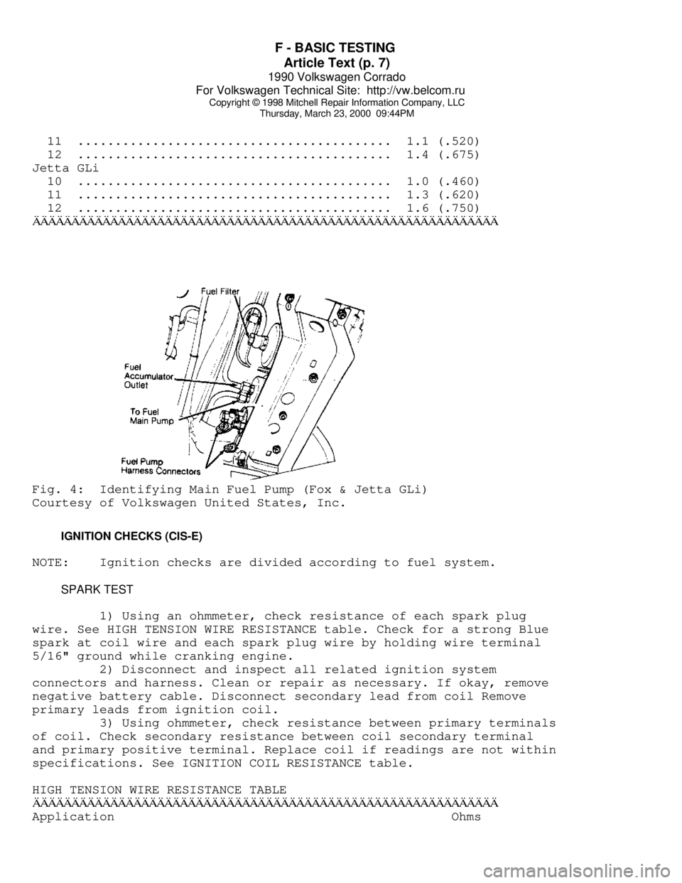
1) Disconnect wire harness connector from fuel pump. See
Fig. 4. With voltmeter attached to terminals, activate fuel pump by
removing fuel pump relay and applying battery voltage to terminals No.
4 of the fuse box connection for the fuel pump relay. Fuel pump relay
located on fuse box housing. Terminal numbers are molded into fuse box
plastic housing.
2) Record voltage. Remove fuel line from outlet side of
accumulator. See Fig. 4. Attach a piece of hose between return line
and a graduated container. Activate fuel pump for 30 seconds. Compare
volume with specifications given in MAIN FUEL PUMP VOLUME (AFC-
Digifant II) table.
VANAGON
1) Remove the return line from the pressure regulator located
in engine compartment left side. Push a piece of hose onto open
connection of pressure regulator. Insert hose into a 1 qt. (1 liter)
graduated container.
2) Activate fuel pump for 30 seconds by removing fuel pump
relay and attaching jumper wire between terminals No. 30 and No. 87.
Fuel pump relay located left side of engine compartment in Black
plastic box. Compare volume with specifications.
FUEL PUMP PERFORMANCE TABLE (AFC-DIGIFANT II)ÄÄÄÄÄÄÄÄÄÄÄÄÄÄÄÄÄÄÄÄÄÄÄÄÄÄÄÄÄÄÄÄÄÄÄÄÄÄÄÄÄÄÄÄÄÄÄÄÄÄÄÄÄÄÄÄÄÄÄÄÄÄÄÄÄÄÄÄÄÄ Pressure Min. Vol. in 30 Sec.
Application psi (kg/cm
ý) Pts. (L)
Cabriolet, Corrado,
Golf GL/GTI & Jetta .... 29-36 (2.0-2.5) ............... 1.0 (.5)
Vanagon ................. 33-39 (2.3-2.7) ............... 1.0 (.5)
ÄÄÄÄÄÄÄÄÄÄÄÄÄÄÄÄÄÄÄÄÄÄÄÄÄÄÄÄÄÄÄÄÄÄÄÄÄÄÄÄÄÄÄÄÄÄÄÄÄÄÄÄÄÄÄÄÄÄÄÄÄÄÄÄÄÄÄÄÄÄFUEL PUMP PERFORMANCE TABLE (CIS-E & CIS-MOTRONIC)
ÄÄÄÄÄÄÄÄÄÄÄÄÄÄÄÄÄÄÄÄÄÄÄÄÄÄÄÄÄÄÄÄÄÄÄÄÄÄÄÄÄÄÄÄÄÄÄÄÄÄÄÄÄÄÄÄÄÄÄÄApplication @ Voltage Min. Vol. in 30 Sec. Pts. (L)
Fox
10 ........................................... .8 (.375)
Page 552 of 906
F - BASIC TESTING
Article Text (p. 7)
1990 Volkswagen Corrado
For Volkswagen Technical Site: http://vw.belcom.ru
Copyright © 1998 Mitchell Repair Information Company, LLC
Thursday, March 23, 2000 09:44PM
11 .......................................... 1.1 (.520)
12 .......................................... 1.4 (.675)
Jetta GLi
10 .......................................... 1.0 (.460)
11 .......................................... 1.3 (.620)
12 .......................................... 1.6 (.750)ÄÄÄÄÄÄÄÄÄÄÄÄÄÄÄÄÄÄÄÄÄÄÄÄÄÄÄÄÄÄÄÄÄÄÄÄÄÄÄÄÄÄÄÄÄÄÄÄÄÄÄÄÄÄÄÄÄÄÄÄFig. 4: Identifying Main Fuel Pump (Fox & Jetta GLi)
Courtesy of Volkswagen United States, Inc.
IGNITION CHECKS (CIS-E)
NOTE: Ignition checks are divided according to fuel system.
SPARK TEST
1) Using an ohmmeter, check resistance of each spark plug
wire. See HIGH TENSION WIRE RESISTANCE table. Check for a strong Blue
spark at coil wire and each spark plug wire by holding wire terminal
5/16" ground while cranking engine.
2) Disconnect and inspect all related ignition system
connectors and harness. Clean or repair as necessary. If okay, remove
negative battery cable. Disconnect secondary lead from coil Remove
primary leads from ignition coil.
3) Using ohmmeter, check resistance between primary terminals
of coil. Check secondary resistance between coil secondary terminal
and primary positive terminal. Replace coil if readings are not within
specifications. See IGNITION COIL RESISTANCE table.
HIGH TENSION WIRE RESISTANCE TABLE
ÄÄÄÄÄÄÄÄÄÄÄÄÄÄÄÄÄÄÄÄÄÄÄÄÄÄÄÄÄÄÄÄÄÄÄÄÄÄÄÄÄÄÄÄÄÄÄÄÄÄÄÄÄÄÄÄÄÄÄÄApplication Ohms
Page 553 of 906
F - BASIC TESTING
Article Text (p. 8)
1990 Volkswagen Corrado
For Volkswagen Technical Site: http://vw.belcom.ru
Copyright © 1998 Mitchell Repair Information Company, LLC
Thursday, March 23, 2000 09:44PM
Fox
Coil Wire With Connectors .................... 1600-2400
Spark Plug Wire With Connectors .............. 4800-7200
Spark Plug Connector ......................... 4000-6000
Suppressor .................................... 800-1200ÄÄÄÄÄÄÄÄÄÄÄÄÄÄÄÄÄÄÄÄÄÄÄÄÄÄÄÄÄÄÄÄÄÄÄÄÄÄÄÄÄÄÄÄÄÄÄÄÄÄÄÄÄÄÄÄÄÄÄÄ IGNITION COIL RESISTANCE TABLE
IGNITION COIL RESISTANCE TABLE - Ohms @ 68
øF (20øC)
ÄÄÄÄÄÄÄÄÄÄÄÄÄÄÄÄÄÄÄÄÄÄÄÄÄÄÄÄÄÄÄÄÄÄÄÄÄÄÄÄÄÄÄÄÄÄÄÄÄÄÄÄÄÄÄÄÄÄÄÄApplication Primary Secondary
Jetta GLi 2.0L ......... .60-.70 ............. 6500-8500
All Other Models ....... .52-.76 ............. 2400-3500
ÄÄÄÄÄÄÄÄÄÄÄÄÄÄÄÄÄÄÄÄÄÄÄÄÄÄÄÄÄÄÄÄÄÄÄÄÄÄÄÄÄÄÄÄÄÄÄÄÄÄÄÄÄÄÄÄÄÄÄÄ DISTRIBUTOR
HALL EFFECT SENDER
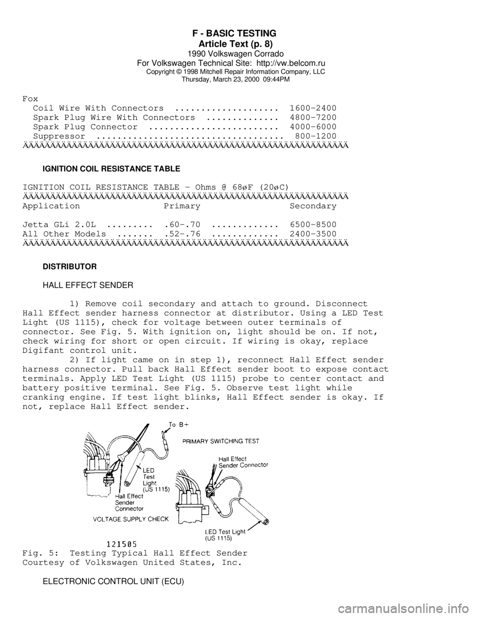
1) Remove coil secondary and attach to ground. Disconnect
Hall Effect sender harness connector at distributor. Using a LED Test
Light (US 1115), check for voltage between outer terminals of
connector. See Fig. 5. With ignition on, light should be on. If not,
check wiring for short or open circuit. If wiring is okay, replace
Digifant control unit.
2) If light came on in step 1), reconnect Hall Effect sender
harness connector. Pull back Hall Effect sender boot to expose contact
terminals. Apply LED Test Light (US 1115) probe to center contact and
battery positive terminal. See Fig. 5. Observe test light while
cranking engine. If test light blinks, Hall Effect sender is okay. If
not, replace Hall Effect sender.Fig. 5: Testing Typical Hall Effect Sender
Courtesy of Volkswagen United States, Inc.
ELECTRONIC CONTROL UNIT (ECU)
Page 554 of 906
F - BASIC TESTING
Article Text (p. 9)
1990 Volkswagen Corrado
For Volkswagen Technical Site: http://vw.belcom.ru
Copyright © 1998 Mitchell Repair Information Company, LLC
Thursday, March 23, 2000 09:44PM
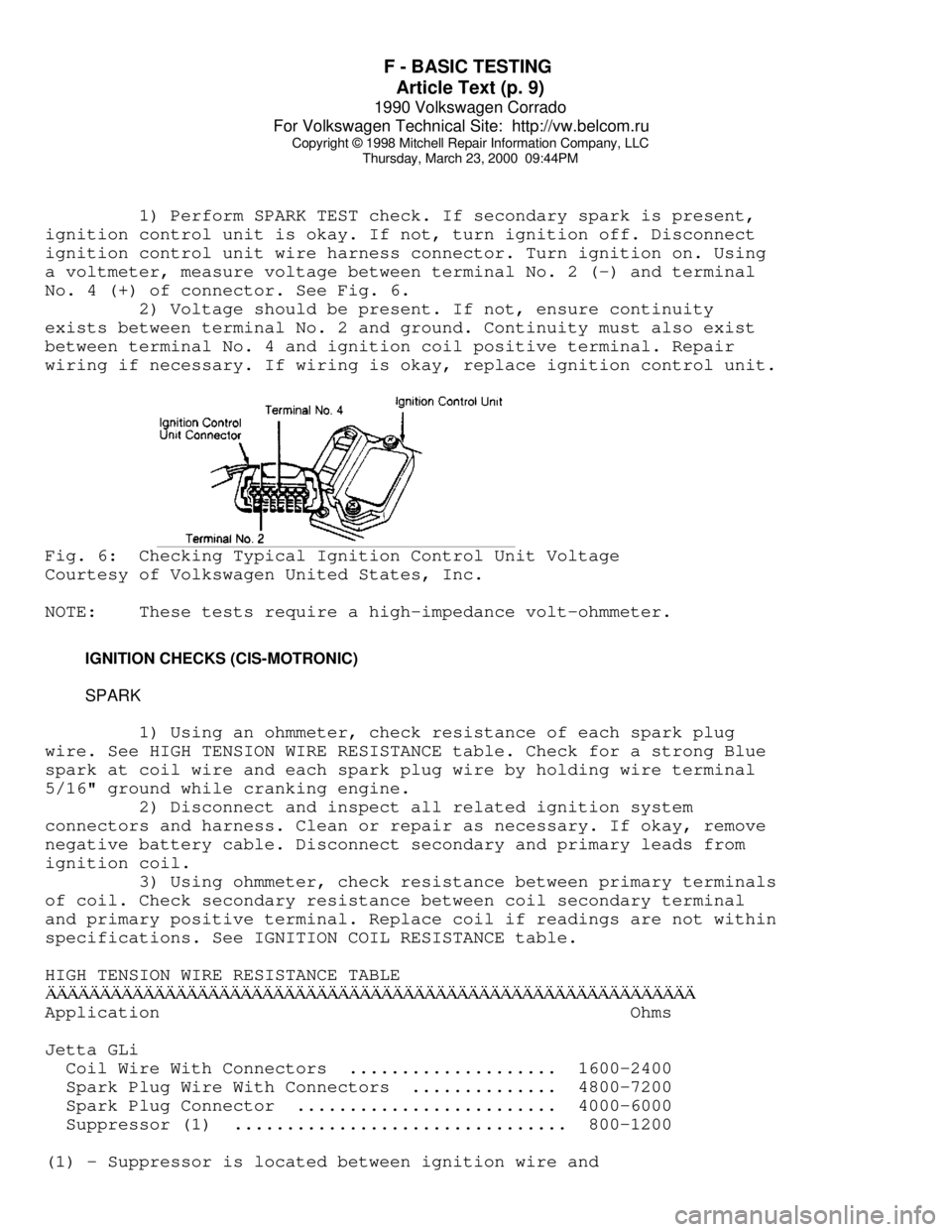
1) Perform SPARK TEST check. If secondary spark is present,
ignition control unit is okay. If not, turn ignition off. Disconnect
ignition control unit wire harness connector. Turn ignition on. Using
a voltmeter, measure voltage between terminal No. 2 (-) and terminal
No. 4 (+) of connector. See Fig. 6.
2) Voltage should be present. If not, ensure continuity
exists between terminal No. 2 and ground. Continuity must also exist
between terminal No. 4 and ignition coil positive terminal. Repair
wiring if necessary. If wiring is okay, replace ignition control unit.Fig. 6: Checking Typical Ignition Control Unit Voltage
Courtesy of Volkswagen United States, Inc.
NOTE: These tests require a high-impedance volt-ohmmeter.
IGNITION CHECKS (CIS-MOTRONIC)
SPARK
1) Using an ohmmeter, check resistance of each spark plug
wire. See HIGH TENSION WIRE RESISTANCE table. Check for a strong Blue
spark at coil wire and each spark plug wire by holding wire terminal
5/16" ground while cranking engine.
2) Disconnect and inspect all related ignition system
connectors and harness. Clean or repair as necessary. If okay, remove
negative battery cable. Disconnect secondary and primary leads from
ignition coil.
3) Using ohmmeter, check resistance between primary terminals
of coil. Check secondary resistance between coil secondary terminal
and primary positive terminal. Replace coil if readings are not within
specifications. See IGNITION COIL RESISTANCE table.
HIGH TENSION WIRE RESISTANCE TABLEÄÄÄÄÄÄÄÄÄÄÄÄÄÄÄÄÄÄÄÄÄÄÄÄÄÄÄÄÄÄÄÄÄÄÄÄÄÄÄÄÄÄÄÄÄÄÄÄÄÄÄÄÄÄÄÄÄÄÄÄApplication Ohms
Jetta GLi
Coil Wire With Connectors .................... 1600-2400
Spark Plug Wire With Connectors .............. 4800-7200
Spark Plug Connector ......................... 4000-6000
Suppressor (1) ................................ 800-1200
(1) - Suppressor is located between ignition wire and