wiring VOLKSWAGEN CORRADO 1990 Service Manual
[x] Cancel search | Manufacturer: VOLKSWAGEN, Model Year: 1990, Model line: CORRADO, Model: VOLKSWAGEN CORRADO 1990Pages: 906, PDF Size: 6.56 MB
Page 423 of 906
ANTI-LOCK BRAKE SYSTEM
Article Text (p. 15)
1990 Volkswagen Corrado
For Volkswagen Technical Site: http://vw.belcom.ru
Copyright © 1998 Mitchell Repair Information Company, LLC
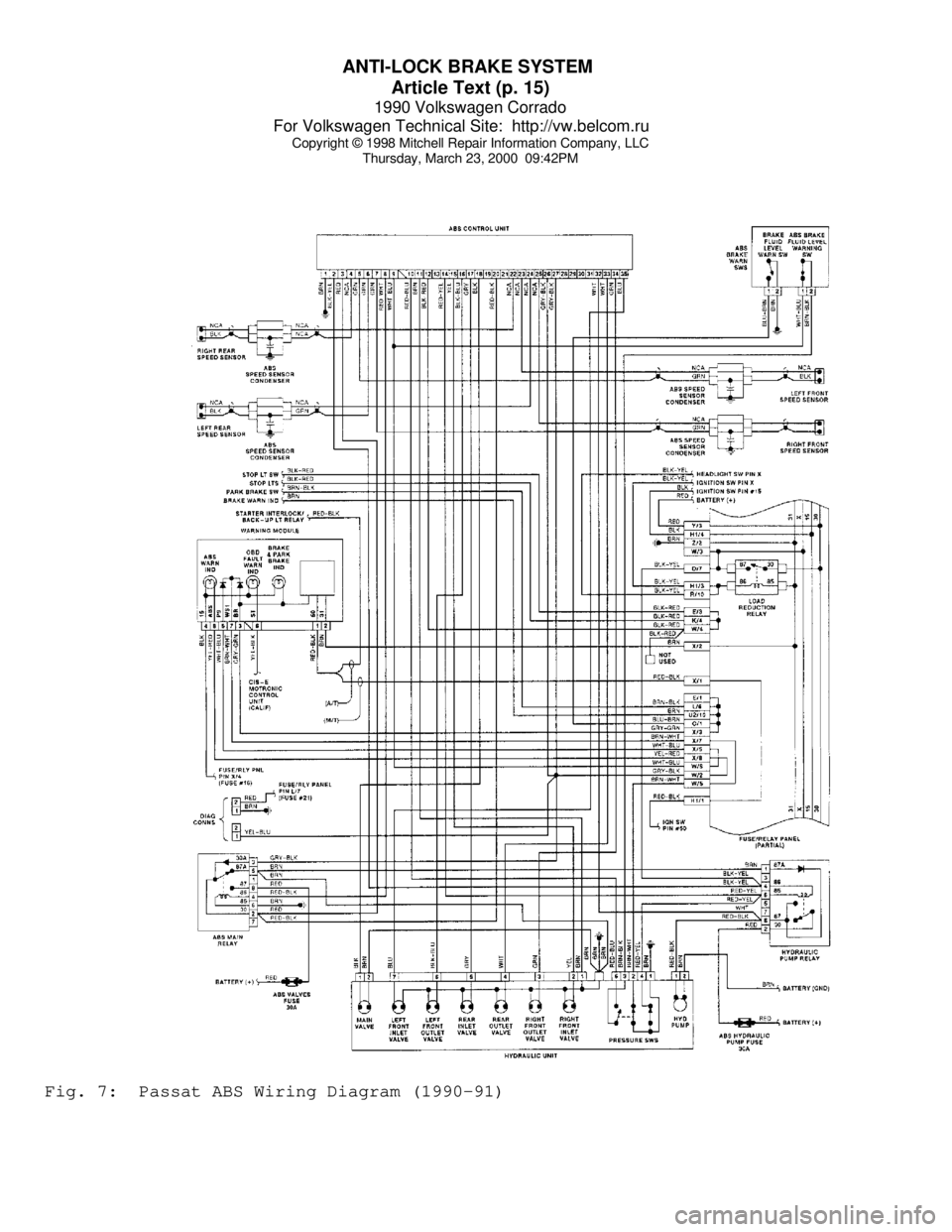
Thursday, March 23, 2000 09:42PMFig. 7: Passat ABS Wiring Diagram (1990-91)
Page 424 of 906
ANTI-LOCK BRAKE SYSTEM
Article Text (p. 16)
1990 Volkswagen Corrado
For Volkswagen Technical Site: http://vw.belcom.ru
Copyright © 1998 Mitchell Repair Information Company, LLC
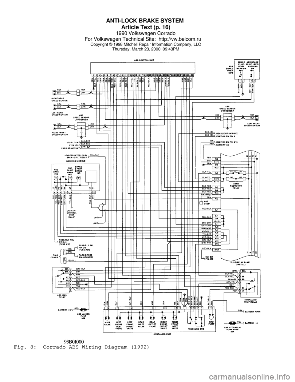
Thursday, March 23, 2000 09:43PMFig. 8: Corrado ABS Wiring Diagram (1992)
Page 425 of 906
ANTI-LOCK BRAKE SYSTEM
Article Text (p. 17)
1990 Volkswagen Corrado
For Volkswagen Technical Site: http://vw.belcom.ru
Copyright © 1998 Mitchell Repair Information Company, LLC
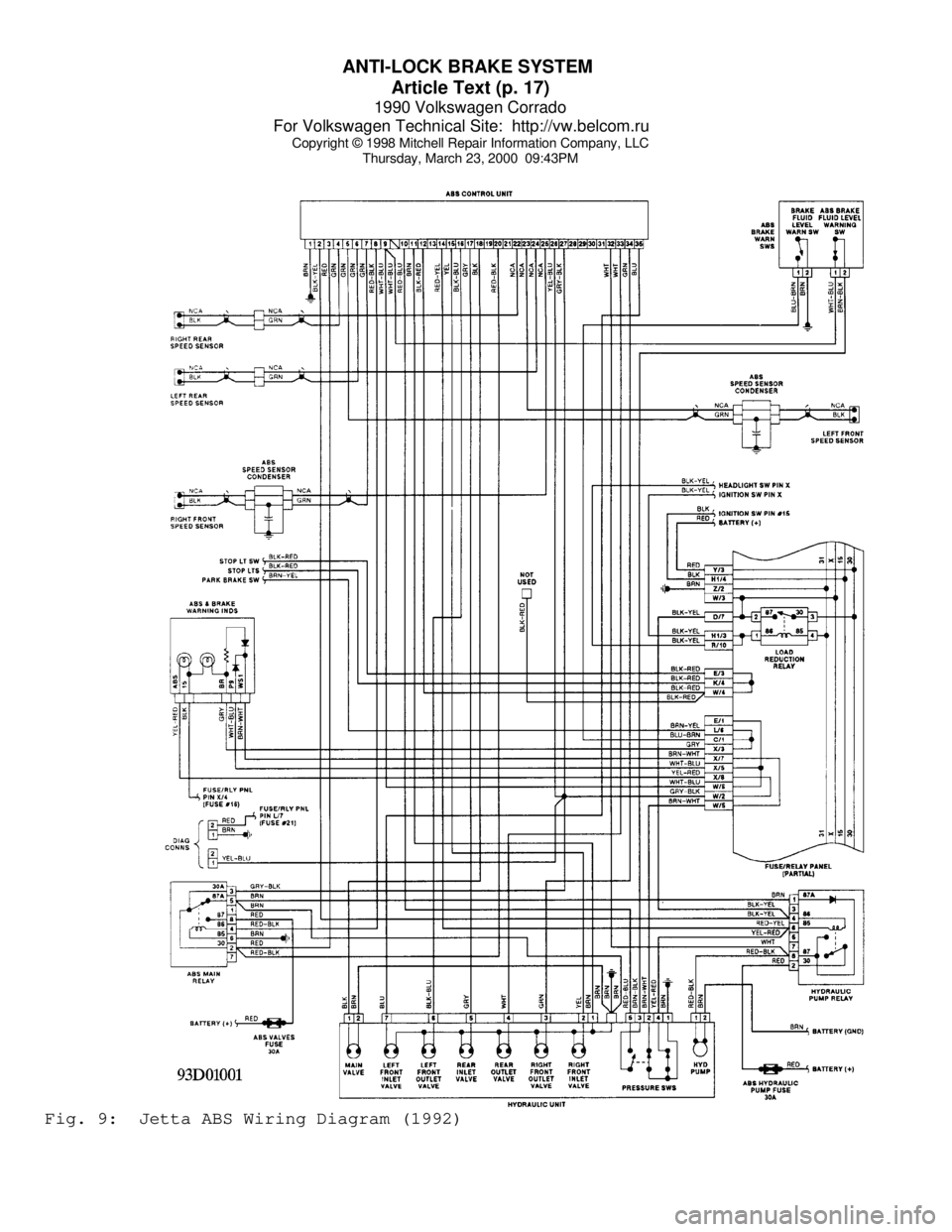
Thursday, March 23, 2000 09:43PMFig. 9: Jetta ABS Wiring Diagram (1992)
Page 426 of 906
ANTI-LOCK BRAKE SYSTEM
Article Text (p. 18)
1990 Volkswagen Corrado
For Volkswagen Technical Site: http://vw.belcom.ru
Copyright © 1998 Mitchell Repair Information Company, LLC
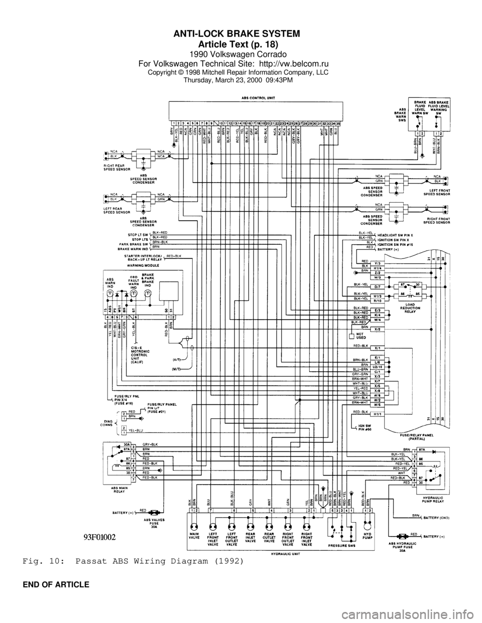
Thursday, March 23, 2000 09:43PMFig. 10: Passat ABS Wiring Diagram (1992)
END OF ARTICLE
Page 442 of 906
D - ADJUSTMENTS
Article Text (p. 5)
1990 Volkswagen Corrado
For Volkswagen Technical Site: http://vw.belcom.ru
Copyright © 1998 Mitchell Repair Information Company, LLC
Thursday, March 23, 2000 09:43PM
8) Connect adapter between connector and regulator. Connect
multimeter to adapter and turn switch to DCA 200 milliamp-range. Read
and compare current (4-16 milliamps) and CO values to specifications.
Turn engine off.
9) If CO reading is more than 1.2% at current reading of 4-16
milliamps, check for exhaust system leaks, ignition timing, injector
inserts for leaks, and fuel distributor for uneven fuel distribution.
If required, seal injector inserts with sealing compound and tighten
to 15 ft. lbs. (20 N.m).
10) If current reading is less than 4 milliamps or more than
16 milliamps, adjustment must be made with CO adjustment screw as
follows: remove boot from mixture control unit. Center punch hole in
CO adjusting hole and drill a 3/32" hole to a depth of 5/32" (4 mm).
DO NOT drill completely through as adjustment screw will be damaged.
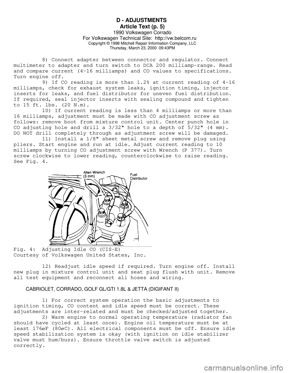
11) Install a 1/8" sheet metal screw and remove plug using
pliers. Start engine and run at idle. Adjust current reading to 10
milliamps by turning CO adjustment screw with Wrench (P 377). Turn
screw clockwise to lower reading, counterclockwise to raise reading.
See Fig. 4.Fig. 4: Adjusting Idle CO (CIS-E)
Courtesy of Volkswagen United States, Inc.
12) Readjust idle speed if required. Turn engine off. Install
new plug in mixture control unit and seat plug flush with unit. Remove
all test equipment and reconnect all hoses and wiring.
CABRIOLET, CORRADO, GOLF GL/GTI 1.8L & JETTA (DIGIFANT II)
1) For correct system operation the basic adjustments to
ignition timing, CO content and idle speed must be correct. These
adjustments are inter-related and must be checked/adjusted together.
2) Warm engine to normal operating temperature (radiator fan
should have cycled at least once). Engine oil temperature must be at
least 176øF (80øC). All electrical components must be off. Ensure idle
speed stabilization system is okay (with ignition on idle stabilizer
valve must hum/buzz). Ensure throttle valve switch is adjusted
correctly.
Page 444 of 906

D - ADJUSTMENTS
Article Text (p. 7)
1990 Volkswagen Corrado
For Volkswagen Technical Site: http://vw.belcom.ru
Copyright © 1998 Mitchell Repair Information Company, LLC
Thursday, March 23, 2000 09:43PM
together. Turn idle speed screw until idle speed is correct. To adjust
timing, see CHECKING & ADJUSTING under IGNITION TIMING in this
article.
3) Ensure all vehicle electrical equipment is off. Place
exhaust gas analyzer in exhaust pipe. See IDLE SPEED & CO LEVEL table.
If adjustment is needed, go to next step.
4) If adjustment is needed in step 2). Remove intake air
sensor from engine. Center punch plug in CO adjusting hole. Using a
3/32" drill bit, drill hole 5/32" (4 mm) deep in center of plug.
Remove any metal shavings. Screw in a sheet metal screw and remove
plug using pliers to pry plug out.
5) Disconnect oxygen sensor connector on left side of engine
compartment (Green wire). Start engine. Set idle speed and CO reading
by alternately turning mixture and idle speed adjustment screws.
Reconnect oxygen sensor and idle stabilizer connectors. Let engine
idle for 2 minutes.
6) Check CO value. If incorrect, repeat adjusting procedure.
If correct turn ignition off. Drive in new adjusting hole plug flush
with air intake sensor. Remove all test equipment and reconnect all
hoses and wiring.
NOTE: Do not push down on adjustment screw and do not accelerate
engine with wrench in plate. Remove wrench after each
adjustment and accelerate engine briefly before measuring
current reading. Always adjust from a high to a low reading.
IDLE SPEED & CO LEVELÄÄÄÄÄÄÄÄÄÄÄÄÄÄÄÄÄÄÄÄÄÄÄÄÄÄÄÄÄÄÄÄÄÄÄÄÄÄÄÄÄÄÄÄÄÄÄÄÄÄÄÄÄÄÄÄÄÄÄÄÄÄÄÄÄÄÄÄÄÄApplication Idle RPM CO Level
Cabriolet .................. 850-1000 ................... 0.3-1.2%
Fox ........................ 800-1000 ................... 0.3-1.2%
Golf ....................... 800-1000 ................... 0.3-1.2%
Golf GT ..................... 800-900 ................... 0.3-1.2%
GTI ........................ 800-1000 ................... 0.3-1.2%
Jetta ...................... 800-1000 ................... 0.3-1.2%
Vanagon ..................... 830-930 ................... 0.3-1.2%
ÄÄÄÄÄÄÄÄÄÄÄÄÄÄÄÄÄÄÄÄÄÄÄÄÄÄÄÄÄÄÄÄÄÄÄÄÄÄÄÄÄÄÄÄÄÄÄÄÄÄÄÄÄÄÄÄÄÄÄÄÄÄÄÄÄÄÄÄÄÄ THROTTLE STOP SCREW
NOTE: Stop screw is set by manufacturer and should not be moved.
If basic factory setting has been changed, turn throttle stop
screw counterclockwise until there is a gap between stop and screw.
Turn screw in until it just touches stop. Turn screw 1/2 turn (180
degrees) further. Check and adjust idle speed and CO.
IDLE & FULL THROTTLE SWITCH ADJUSTMENTS
IDLE SWITCH ADJUSTMENT DIGIFANT II (EXCEPT VANAGON)
Page 445 of 906
D - ADJUSTMENTS
Article Text (p. 8)
1990 Volkswagen Corrado
For Volkswagen Technical Site: http://vw.belcom.ru
Copyright © 1998 Mitchell Repair Information Company, LLC
Thursday, March 23, 2000 09:43PM
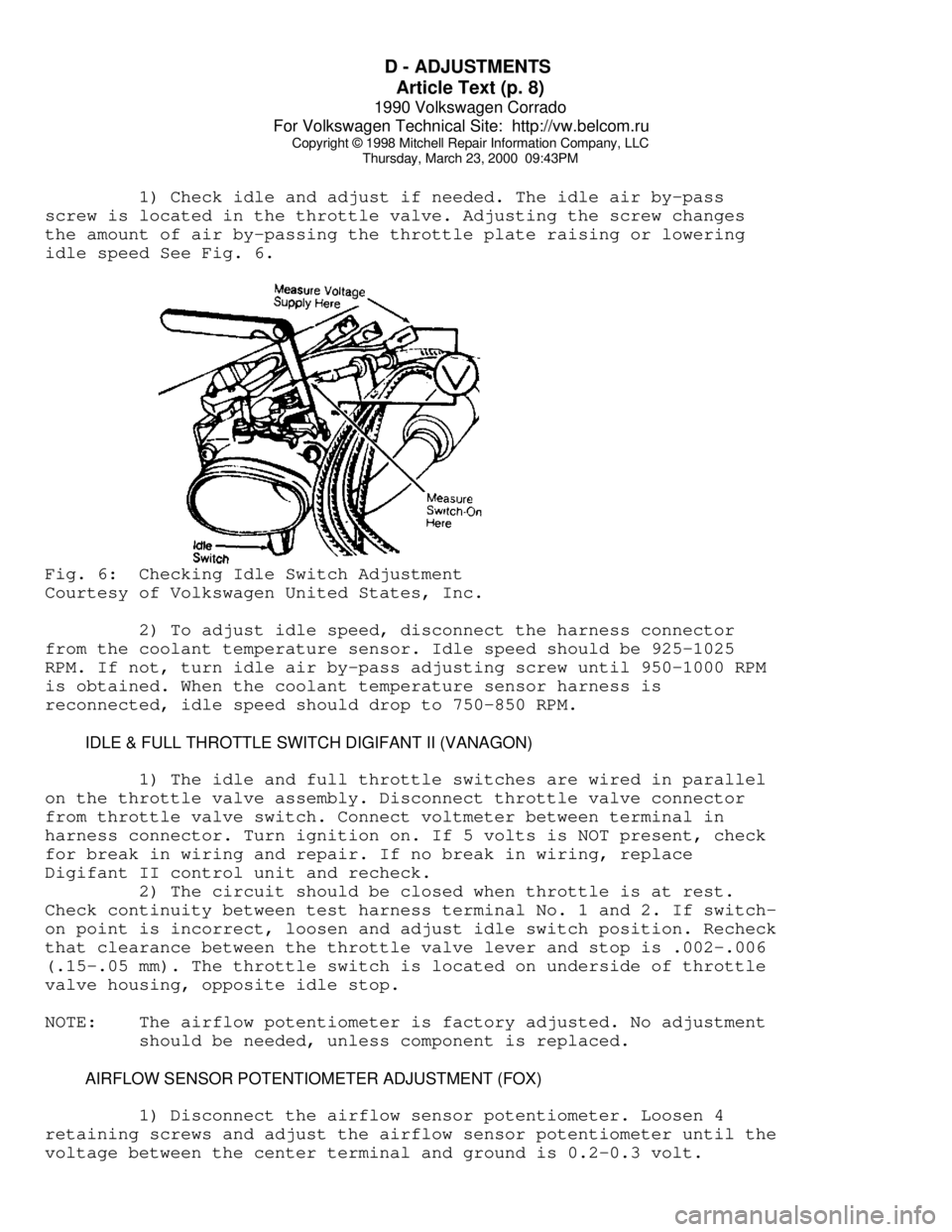
1) Check idle and adjust if needed. The idle air by-pass
screw is located in the throttle valve. Adjusting the screw changes
the amount of air by-passing the throttle plate raising or lowering
idle speed See Fig. 6.Fig. 6: Checking Idle Switch Adjustment
Courtesy of Volkswagen United States, Inc.
2) To adjust idle speed, disconnect the harness connector
from the coolant temperature sensor. Idle speed should be 925-1025
RPM. If not, turn idle air by-pass adjusting screw until 950-1000 RPM
is obtained. When the coolant temperature sensor harness is
reconnected, idle speed should drop to 750-850 RPM.
IDLE & FULL THROTTLE SWITCH DIGIFANT II (VANAGON)
1) The idle and full throttle switches are wired in parallel
on the throttle valve assembly. Disconnect throttle valve connector
from throttle valve switch. Connect voltmeter between terminal in
harness connector. Turn ignition on. If 5 volts is NOT present, check
for break in wiring and repair. If no break in wiring, replace
Digifant II control unit and recheck.
2) The circuit should be closed when throttle is at rest.
Check continuity between test harness terminal No. 1 and 2. If switch-
on point is incorrect, loosen and adjust idle switch position. Recheck
that clearance between the throttle valve lever and stop is .002-.006
(.15-.05 mm). The throttle switch is located on underside of throttle
valve housing, opposite idle stop.
NOTE: The airflow potentiometer is factory adjusted. No adjustment
should be needed, unless component is replaced.
AIRFLOW SENSOR POTENTIOMETER ADJUSTMENT (FOX)
1) Disconnect the airflow sensor potentiometer. Loosen 4
retaining screws and adjust the airflow sensor potentiometer until the
voltage between the center terminal and ground is 0.2-0.3 volt.
Page 459 of 906
E - THEORY/OPERATION - DIGIFANT
Article Text (p. 9)
1990 Volkswagen Corrado
For Volkswagen Technical Site: http://vw.belcom.ru
Copyright © 1998 Mitchell Repair Information Company, LLC
Thursday, March 23, 2000 09:43PM
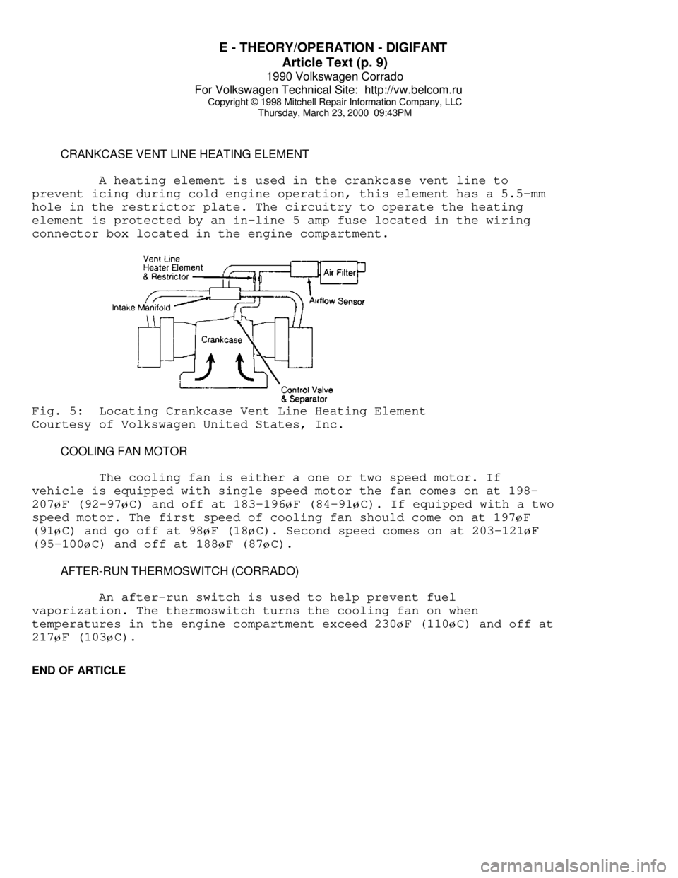
CRANKCASE VENT LINE HEATING ELEMENT
A heating element is used in the crankcase vent line to
prevent icing during cold engine operation, this element has a 5.5-mm
hole in the restrictor plate. The circuitry to operate the heating
element is protected by an in-line 5 amp fuse located in the wiring
connector box located in the engine compartment.Fig. 5: Locating Crankcase Vent Line Heating Element
Courtesy of Volkswagen United States, Inc.
COOLING FAN MOTOR
The cooling fan is either a one or two speed motor. If
vehicle is equipped with single speed motor the fan comes on at 198-
207øF (92-97øC) and off at 183-196øF (84-91øC). If equipped with a two
speed motor. The first speed of cooling fan should come on at 197
øF
(91
øC) and go off at 98øF (18øC). Second speed comes on at 203-121øF
(95-100
øC) and off at 188øF (87øC).
AFTER-RUN THERMOSWITCH (CORRADO)
An after-run switch is used to help prevent fuel
vaporization. The thermoswitch turns the cooling fan on when
temperatures in the engine compartment exceed 230
øF (110øC) and off at
217
øF (103øC).
END OF ARTICLE
Page 546 of 906

F - BASIC TESTING
Article Text
1990 Volkswagen Corrado
For Volkswagen Technical Site: http://vw.belcom.ru
Copyright © 1998 Mitchell Repair Information Company, LLC
Thursday, March 23, 2000 09:44PM
ARTICLE BEGINNING
1990 ENGINE PERFORMANCE
Volkswagen Basic Diagnostic Procedures
Cabriolet, Corrado, Fox, Golf GL/GTI, Jetta, Vanagon
INTRODUCTION
The following diagnostic steps will help prevent overlooking
a simple problem. This is also where to begin diagnosis for a no start
condition.
The first step in diagnosing any driveability problem is
verifying the customer's complaint with a test drive under the
conditions the problem reportedly occurred.
Perform a careful and complete visual inspection. Most engine
control problems result from mechanical breakdowns, poor electrical
connections or damaged/misrouted vacuum hoses. Before condemning the
computerized system, perform each test listed in this article.
NOTE: Perform all voltage tests with a Digital Volt-Ohmmeter
(DVOM) with a minimum 10-megohm input impedance, unless
stated otherwise in test procedure.
VISUAL INSPECTION
Visually inspect all electrical wiring, looking for chafed,
stretched, cut or pinched wiring. Ensure electrical connectors fit
tightly and are not corroded. Ensure vacuum hoses are properly routed
and are not pinched or cut. See M - VACUUM DIAGRAMS article to verify
routing and connections (if necessary). Inspect air induction system
for possible vacuum leaks.
MECHANICAL INSPECTION
COMPRESSION
Check engine mechanical condition with a compression gauge,
vacuum gauge, or an engine analyzer. See engine analyzer manual for
specific instructions.
DO NOT use ignition switch during compression tests on fuel
injected vehicles. Use a remote starter to crank engine. Fuel
injectors on many models are triggered by ignition switch during
cranking mode, which can create a fire hazard or contaminate the
engine's oiling system.
EXHAUST SYSTEM BACKPRESSURE
The exhaust system can be checked with a vacuum or pressure
gauge. Remove O2 sensor or air injection check valve (if equipped).
Connect a 1-10 psi pressure gauge and run engine at 2500 RPM. If
Page 550 of 906
F - BASIC TESTING
Article Text (p. 5)
1990 Volkswagen Corrado
For Volkswagen Technical Site: http://vw.belcom.ru
Copyright © 1998 Mitchell Repair Information Company, LLC
Thursday, March 23, 2000 09:44PM
to OFF position.
(2) - With pressure regulator vacuum hose disconnected, pressure
should be 36 psi (2.5 kg/cmý).
ÄÄÄÄÄÄÄÄÄÄÄÄÄÄÄÄÄÄÄÄÄÄÄÄÄÄÄÄÄÄÄÄÄÄÄÄÄÄÄÄÄÄÄÄÄÄÄÄÄÄÄÄÄÄÄÄÄÄÄÄÄÄÄÄÄÄÄÄÄÄ TRANSFER PUMP CHECK
TRANSFER PUMP FUEL VOLUME CHECK
1) Turn ignition off. To check transfer pump (in tank),
remove rear seat. Remove fuel sending unit access cover. Disconnect
ignition coil secondary wire and jumper to ground. With transmission
in neutral, crank engine for a 3-4 seconds. While the starter is
turning and for a few seconds afterwards, an audible sound should be
heard at the pump. If not, proceed to step 2).
2) Activate fuel pumps by removing fuel pump relay and
attaching jumper wire between terminals No. 30 battery voltage and No.
87 output to fuel pumps. Terminal identification is molded on
fuse/relay panel. If pump does not operate, remove transfer pump
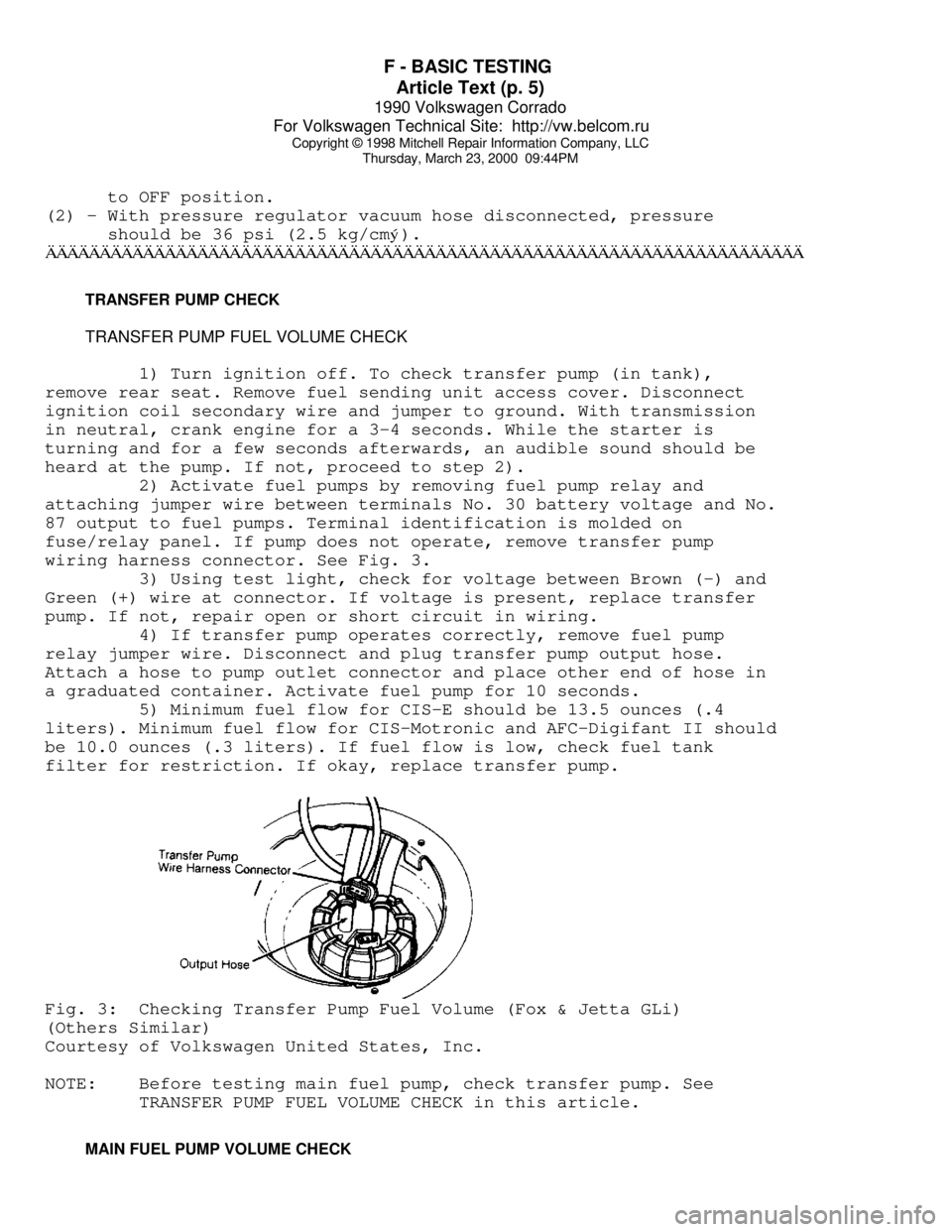
wiring harness connector. See Fig. 3.
3) Using test light, check for voltage between Brown (-) and
Green (+) wire at connector. If voltage is present, replace transfer
pump. If not, repair open or short circuit in wiring.
4) If transfer pump operates correctly, remove fuel pump
relay jumper wire. Disconnect and plug transfer pump output hose.
Attach a hose to pump outlet connector and place other end of hose in
a graduated container. Activate fuel pump for 10 seconds.
5) Minimum fuel flow for CIS-E should be 13.5 ounces (.4
liters). Minimum fuel flow for CIS-Motronic and AFC-Digifant II should
be 10.0 ounces (.3 liters). If fuel flow is low, check fuel tank
filter for restriction. If okay, replace transfer pump.Fig. 3: Checking Transfer Pump Fuel Volume (Fox & Jetta GLi)
(Others Similar)
Courtesy of Volkswagen United States, Inc.
NOTE: Before testing main fuel pump, check transfer pump. See
TRANSFER PUMP FUEL VOLUME CHECK in this article.
MAIN FUEL PUMP VOLUME CHECK