wiring VOLKSWAGEN CORRADO 1990 Owner's Manual
[x] Cancel search | Manufacturer: VOLKSWAGEN, Model Year: 1990, Model line: CORRADO, Model: VOLKSWAGEN CORRADO 1990Pages: 906, PDF Size: 6.56 MB
Page 367 of 906
A/C-HEATER SYSTEM - MANUAL
Article Text (p. 10)
1990 Volkswagen Corrado
For Volkswagen Technical Site: http://vw.belcom.ru
Copyright © 1998 Mitchell Repair Information Company, LLC
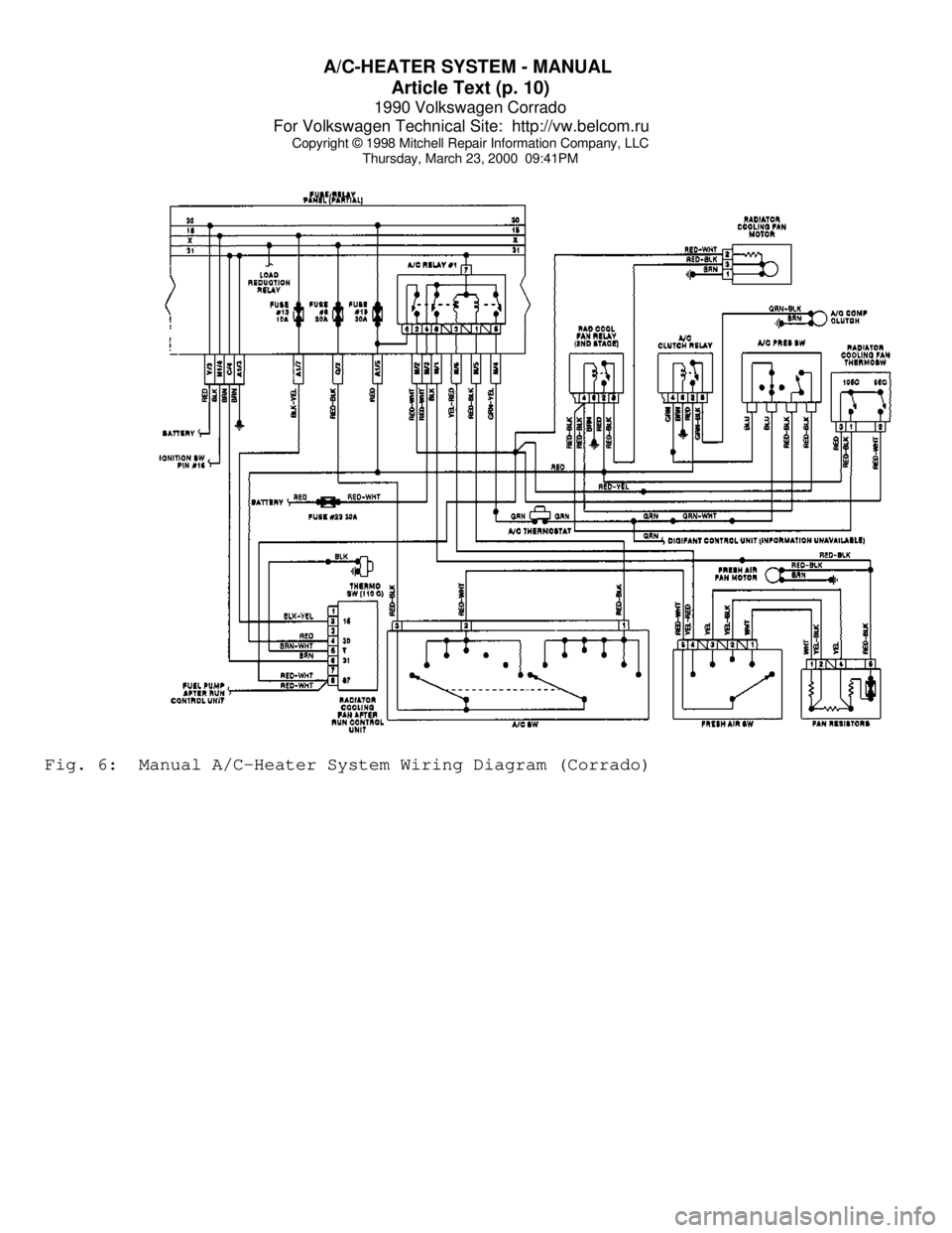
Thursday, March 23, 2000 09:41PMFig. 6: Manual A/C-Heater System Wiring Diagram (Corrado)
Page 368 of 906
A/C-HEATER SYSTEM - MANUAL
Article Text (p. 11)
1990 Volkswagen Corrado
For Volkswagen Technical Site: http://vw.belcom.ru
Copyright © 1998 Mitchell Repair Information Company, LLC
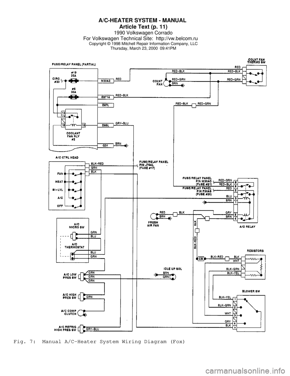
Thursday, March 23, 2000 09:41PMFig. 7: Manual A/C-Heater System Wiring Diagram (Fox)
Page 369 of 906
A/C-HEATER SYSTEM - MANUAL
Article Text (p. 12)
1990 Volkswagen Corrado
For Volkswagen Technical Site: http://vw.belcom.ru
Copyright © 1998 Mitchell Repair Information Company, LLC
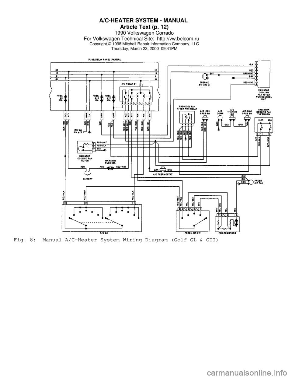
Thursday, March 23, 2000 09:41PMFig. 8: Manual A/C-Heater System Wiring Diagram (Golf GL & GTI)
Page 370 of 906
A/C-HEATER SYSTEM - MANUAL
Article Text (p. 13)
1990 Volkswagen Corrado
For Volkswagen Technical Site: http://vw.belcom.ru
Copyright © 1998 Mitchell Repair Information Company, LLC
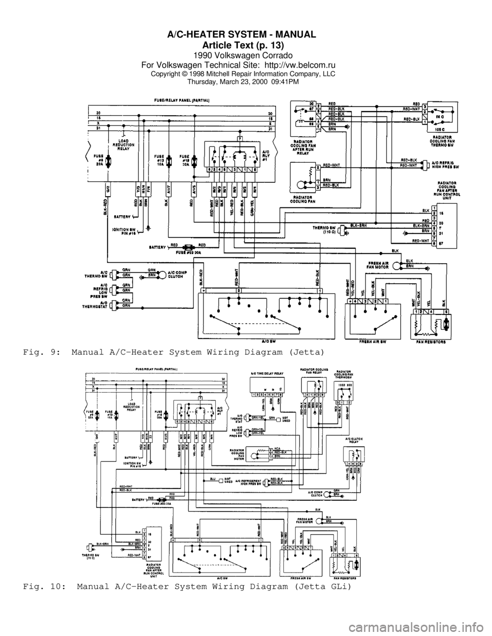
Thursday, March 23, 2000 09:41PMFig. 9: Manual A/C-Heater System Wiring Diagram (Jetta)Fig. 10: Manual A/C-Heater System Wiring Diagram (Jetta GLi)
Page 371 of 906
A/C-HEATER SYSTEM - MANUAL
Article Text (p. 14)
1990 Volkswagen Corrado
For Volkswagen Technical Site: http://vw.belcom.ru
Copyright © 1998 Mitchell Repair Information Company, LLC
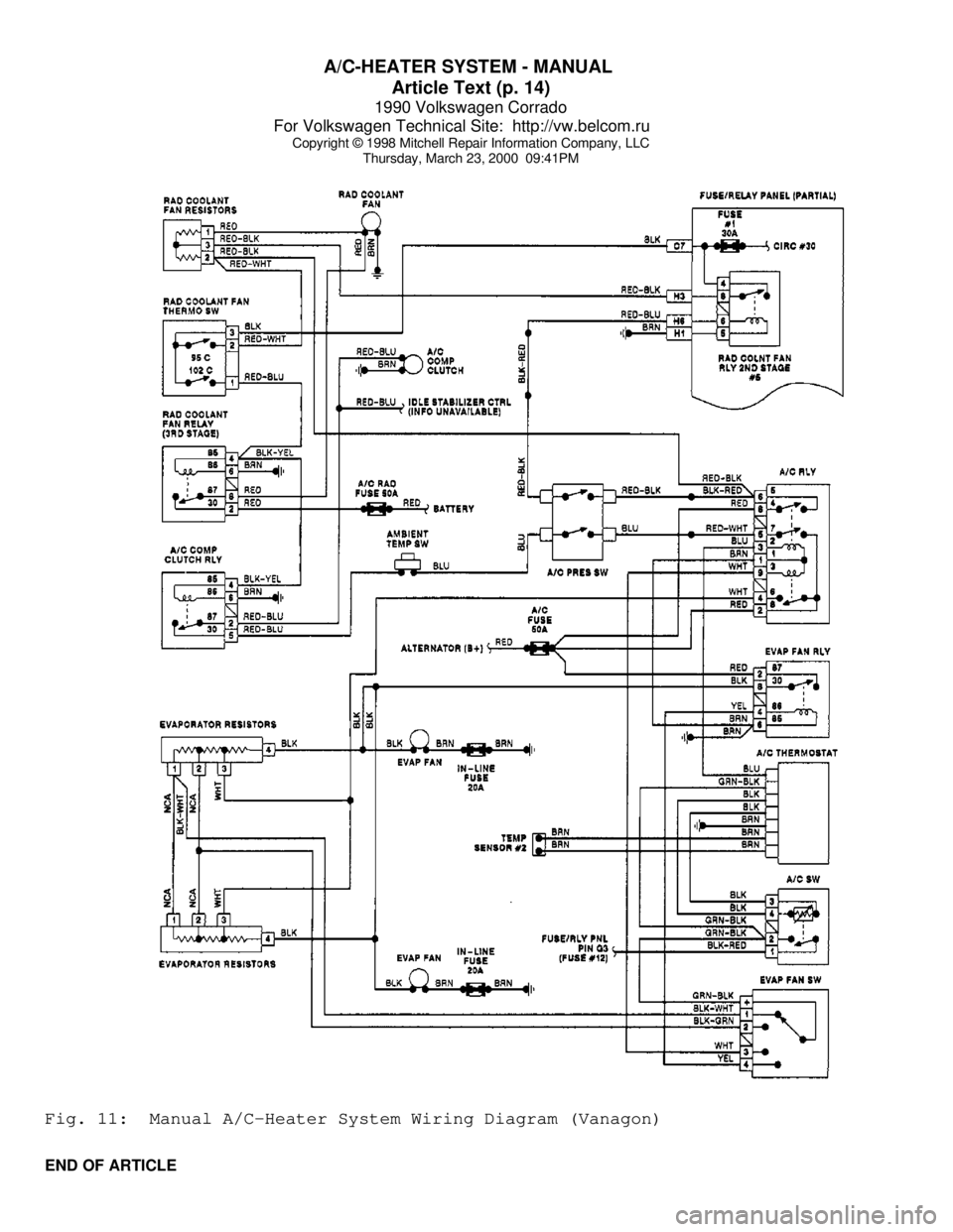
Thursday, March 23, 2000 09:41PMFig. 11: Manual A/C-Heater System Wiring Diagram (Vanagon)
END OF ARTICLE
Page 372 of 906

AA - USING THIS SECTION (GENERAL HELP INFORMATION)
Article Text
1990 Volkswagen Corrado
For Volkswagen Technical Site: http://vw.belcom.ru
Copyright © 1998 Mitchell Repair Information Company, LLC
Thursday, March 23, 2000 09:41PM
ARTICLE BEGINNING
ENGINE PERFORMANCE
How To Use This Section
INTRODUCTION
NOTE: Because there are so many possible combinations of
articles for the different manufacturers and models,
the new hyper-text capabilities built into this product
DO NOT apply to this article.
It is the purpose of this repair information system to help
professional automotive technicians maintain top vehicle performance
and correct driveability problems related to today's high tech
vehicles.
Because of the limited amount of space allowable for the this
product, our titles have been condensed to fit into the menus. An
alphabetical designation has been added to the front of each title to
allow the titles to be displayed in a way that reflects their
respective order of use. References to the titles in some of the
diagnostic flow charts sometimes will not correlate with the titles in
the this product menu. If not, refer to the MENU CROSS-REFERENCE table
below.
MENU CROSS-REFERENCE TABLEÄÄÄÄÄÄÄÄÄÄÄÄÄÄÄÄÄÄÄÄÄÄÄÄÄÄÄÄÄÄÄÄÄÄÄÄÄÄÄÄÄÄÄÄÄÄÄÄÄÄÄÄÄÄÄÄÄÄÄÄÄÄÄÄÄÄÄÄÄÄTitle Associate Print (Book) Title:
A - ENGINE/VIN I D .................................... Introduction
B - EMISSION APPLICATION ..................... Emission Applications
C - TUNE-UP SPECS .............. Service & Adjustment Specifications
C - SPECIFICATIONS ............. Service & Adjustment Specifications
D - ADJUSTMENTS ............................. On-Vehicle Adjustments
E - THEORY/OPERATION ............................ Theory & Operation
F - BASIC TESTING ...................... Basic Diagnostic Procedures
G - TESTS W/ CODES ................................ Self-Diagnostics
H - TESTS W/O CODES .................... Trouble Shooting - No Codes
I - SYS/COMP TESTS ..................... Systems & Component Testing
J - PIN VOLTAGE CHARTS .......................... Pin Voltage Charts
K - SENSOR RANGE CHARTS .............. Sensor Operating Range Charts
L - WIRING DIAGRAMS ................................ Wiring Diagrams
M - VACUUM DIAGRAMS ................................ Vacuum Diagrams
N - REMOVE/INSTALL/OHAUL .......... Removal, Overhaul & Installation
ÄÄÄÄÄÄÄÄÄÄÄÄÄÄÄÄÄÄÄÄÄÄÄÄÄÄÄÄÄÄÄÄÄÄÄÄÄÄÄÄÄÄÄÄÄÄÄÄÄÄÄÄÄÄÄÄÄÄÄÄÄÄÄÄÄÄÄÄÄÄ Because of this we recommend that you read the rest of these
INTRODUCTION paragraphs to better understand why the information is
presented in this new format.
The A - ENGINE/VIN I D article will help you identify the
vehicle and its systems. It will also explain the VIN code and in many
cases, show its location.
Page 373 of 906

AA - USING THIS SECTION (GENERAL HELP INFORMATION)
Article Text (p. 2)
1990 Volkswagen Corrado
For Volkswagen Technical Site: http://vw.belcom.ru
Copyright © 1998 Mitchell Repair Information Company, LLC
Thursday, March 23, 2000 09:41PM
If you want "TUNE-UP" type information, see D - ADJUSTMENTS
for the adjustment procedures. If you are familiar with the
procedures, but need a quick way to find the specification, go to C -
TUNE-UP SPECS or C - SPECIFICATIONS for the specifications pertaining
to the vehicle.
When diagnosing driveability problems, first go to F - BASIC
TESTING. This article is here to help eliminate wasted diagnostic
time. If the basic systems are working properly, go to G - TESTS W/
CODES.
If the vehicle still is having a driveability problem or if
the vehicle has no self-diagnostic system, go to H - TESTS W/O CODES.
This article will help you diagnose the problem by symptom, locate the
symptom exhibited by the vehicle, and inspect or test the items which
may be causing the problem.
After finding which specific system or component requires
testing, use the I - SYS/COMP TESTS article to tests the systems and
components. We have also included (when available) pin voltage charts
and sensor range charts. These can be found in J - PIN VOLTAGE CHARTS
and K - SENSOR RANGE CHARTS.
Also included in this section are wiring diagrams and vacuum
diagrams. These can be found in L - WIRING DIAGRAMS and M - VACUUM
DIAGRAMS.
When all diagnostic tests have been performed and the problem
has been discovered, it may be necessary to replace or overhaul the
defective part. This information can be found in
N - REMOVE/INSTALL/OHAUL.
The content of each of these articles is outlined below. As a
summary of the driveability diagnosis, see ROUTINE OUTLINE in this
article.
A - ENGINE/VIN ID
This article shows how to identify the model and engine by
its Vehicle Identification Number (VIN). A model coverage chart shows
each model and engine, the fuel system, ignition system and engine
code. The engine serial number locations are also included in this
article.
B - EMISSION APPLICATION
These charts identify the emission systems and sub-systems
applicable to each model and engine combination.
C - TUNE-UP SPECS
This is a collection of quick-reference type specifications.
This article is helpful when you are familiar with proper adjustment
procedures and only need specifications. Included in this section are:
* Battery specifications.
* Fluid capacities.
Page 376 of 906

AA - USING THIS SECTION (GENERAL HELP INFORMATION)
Article Text (p. 5)
1990 Volkswagen Corrado
For Volkswagen Technical Site: http://vw.belcom.ru
Copyright © 1998 Mitchell Repair Information Company, LLC
Thursday, March 23, 2000 09:41PM
sensor is out of calibration. A sensor that is out of calibration may
not set a trouble code, but it will cause driveability problems.
L - WIRING DIAGRAMS
Use these WIRING DIAGRAMS to identify and trace component
circuits, locate shorts and opens in circuits, and understand how
individual circuits function as part of a system. The diagrams in this
article are only for fuel, ignition and emission systems
M - VACUUM DIAGRAMS
The VACUUM DIAGRAMS will assist you in finding incorrectly
routed vacuum hoses which may cause driveability problems or computer
indicated malfunctions.
N - REMOVE/INSTALL/OHAUL
N - REMOVE/INSTALL/OHAUL contains information found in the
sub-headings of REMOVAL, OVERHAUL & INSTALLATION. These are procedures
and specifications required to remove, overhaul (if possible) and
install components related to engine performance.
WHERE TO START
PERFORM BASIC INSPECTION
1) Verify customer complaint.
2) Perform visual inspection. See F - BASIC TESTING.
3) Test engine sub-system to determine that the following
systems are functioning properly. See F- BASIC TESTING.
* Mechanical conditions (compression)
* Ignition output
* Fuel Delivery
4) Check air induction system for leaks.
5) Check & adjust basic engine settings listed below to
ensure they are to specification. See D - ADJUSTMENTS.
* Ignition timing
* Idle speed
CHECK FOR TROUBLE CODES
1) If equipped with self-diagnostics, check for trouble
codes. Refer to G - TESTS W/ CODES.
2) Repair causes of trouble code(s).
3) Clear control unit memory.
SYMPTOM DIAGNOSIS
Page 402 of 906

ALTERNATOR & REGULATOR - BOSCH
Article Text
1990 Volkswagen Corrado
For Volkswagen Technical Site: http://vw.belcom.ru
Copyright © 1998 Mitchell Repair Information Company, LLC
Thursday, March 23, 2000 09:42PM
ARTICLE BEGINNING
1989-92 ELECTRICAL
Alternators & Regulators - Bosch
Cabriolet, Fox, Golf, GTI, Jetta, Jetta GLI, Vanagon
1991 Corrado, Passat & Golf GL
NOTE: Some Golf, GTI, Jetta and Jetta GLI models may use a
Motorola alternator. Please refer to ALTERNATORS - SEV
MOTOROLA article. Vanagon models only use Bosch 90-amp
alternators.
DESCRIPTION
Bosch alternators are conventional 3-phase, self-rectifying
type alternators. Bosch 65 through 75-amp alternators use 3 positive
and 3 negative diodes connected to stator windings to rectify current.
Bosch 90-amp alternators use 14 diodes.
All alternators use 3 exciter diodes connected to stator
windings. These diodes turn off the alternator indicator light and
supply power to the voltage regulator while the engine is running.
Bosch regulators are transistorized and integral with alternator.
BELT TENSION ADJUSTMENT
BELT TENSION SPECIFICATIONSÄÄÄÄÄÄÄÄÄÄÄÄÄÄÄÄÄÄÄÄÄÄÄÄÄÄÄÄÄÄÄÄÄÄÄÄÄÄÄÄÄÄÄÄÄÄÄÄÄÄÄÄÄÄÄApplication (1) Deflection In. (mm)
New Belt ................................... 5/64 (2)
Used Belt ................................. 13/64 (5)
(1) - Deflection is with 22 lbs. (10 kg) pressure
applied midway on longest belt run.
ÄÄÄÄÄÄÄÄÄÄÄÄÄÄÄÄÄÄÄÄÄÄÄÄÄÄÄÄÄÄÄÄÄÄÄÄÄÄÄÄÄÄÄÄÄÄÄÄÄÄÄÄÄÄÄ TESTING (ON-VEHICLE)
WIRING CONTINUITY TEST
1) Connect a voltmeter between alternator "B+" terminal and
ground. Voltmeter should indicate battery voltage. If not, check
wiring between alternator and battery.
2) Turn ignition on and ensure alternator indicator light
comes on. If light does not come on, check wiring between alternator
and warning light, including indicator bulb.
OUTPUT TEST
1) Ensure connections at battery, alternator, and starter
Page 412 of 906
ANTI-LOCK BRAKE SYSTEM
Article Text (p. 4)
1990 Volkswagen Corrado
For Volkswagen Technical Site: http://vw.belcom.ru
Copyright © 1998 Mitchell Repair Information Company, LLC
Thursday, March 23, 2000 09:42PM
seconds maximum and then stop. Depress brake pedal a few times; pump
should operate again for a few seconds. If pump motor does not
operate, check electrical system. If pump motor operates for more than
60 seconds, internal or external hydraulic leak may be indicated.
Check for external leaks. If external leak is not found, further
testing may be needed to check for internal leaks.
ANTI-LOCK WARNING LIGHT
Start engine. ANTI-LOCK warning light should come on, then
turn off after a few seconds. If light does not come on when engine is
started, check electrical system. If light comes on and stays on,
fault has been detected by the ECU and testing will be needed. See
SYSTEM TESTING under DIAGNOSIS & TESTING.
DIAGNOSIS & TESTING
SYSTEM TESTING
NOTE: Check battery condition, brake fluid level, electrical
connections and wiring for damage. If fluid level is
incorrect or battery and/or electrical connections are
faulty, correct problem before preceding. Perform each step,
in sequence, to test entire system, except for ECU. If
faulty ECU is suspected, replace with a known good one, and
retest system. Unplug ECU connector for all test steps.
Power Voltage-To-ECU Test
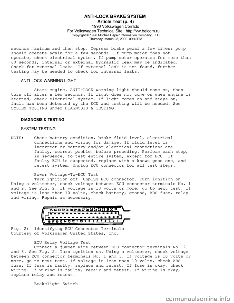
Turn ignition off. Unplug ECU connector. Turn ignition on.
Using a voltmeter, check voltage between ECU connector terminals No. 1
and 2. See Fig. 2. If voltage is 10 volts or more, go to next test. If
voltage is less than 10 volts, check battery, ground, ABS fuse, relay
and wiring. Repair as necessary.Fig. 2: Identifying ECU Connector Terminals
Courtesy of Volkswagen United States, Inc.
ECU Relay Voltage Test
Connect a jumper wire between ECU connector terminals No. 2
and 8. See Fig. 2. Turn ignition on. Using a voltmeter, check voltage
between ECU connector terminals No. 1 and 3. If voltage is 10 volts or
more, go to next test. If voltage is less than 10 volts, check ABS
fuse. If fuse is faulty, replace and retest. If fuse is okay, check
wiring. If wiring is faulty, repair and retest. If wiring is okay,
replace relay and retest.
Brakelight Switch