battery VOLKSWAGEN CORRADO 1993 User Guide
[x] Cancel search | Manufacturer: VOLKSWAGEN, Model Year: 1993, Model line: CORRADO, Model: VOLKSWAGEN CORRADO 1993Pages: 920, PDF Size: 6.92 MB
Page 385 of 920

A/C-HEATER SYSTEM - MANUAL
Article Text (p. 10)
1993 Volkswagen Corrado
For Volkswagen Technical Site: http://vw.belcom.ru
Copyright © 1998 Mitchell Repair Information Company, LLC
Wednesday, March 22, 2000 08:49PM
INSTRUMENT PANEL
Removal & Installation
1) Disable air bag system. See AIR BAG SYSTEM SAFETY article
in GENERAL SERVICING. Disconnect battery. Remove storage trays and
panel under left side of instrument panel. Remove steering wheel.
Remove trim panel around instrument cluster.
2) Remove center console. Remove dash vents at each side,
glove box and radio. Remove center storage box, A/C-heater control
panel trim, and A/C-heater control panel screws. Push A/C-heater
control panel away from instrument panel.
3) Remove screws at both sides of instrument panel, at center
support, and 2 screws next to windshield. Detach instrument panel and
pull part way out.
4) Disconnect wiring harnesses from instrument panel.
Disconnect speedometer cable, if present. Remove instrument panel. To
install, reverse removal procedure.
THERMOSTAT
Removal & Installation
1) Remove thermostat cover. See Fig. 3. Remove thermostat
mounting screw and disconnect harness connector. Remove thermostat by
pulling sensing (capillary) tube through grommet.
2) To install, reverse removal procedures. Measure back 13"
(330 mm) from end of sensing tube and tape spot. Insert sensing tube
into evaporator guide channel up to tape.
TORQUE SPECIFICATIONS
TORQUE SPECIFICATIONS TABLEÄÄÄÄÄÄÄÄÄÄÄÄÄÄÄÄÄÄÄÄÄÄÄÄÄÄÄÄÄÄÄÄÄÄÄÄÄÄÄÄÄÄÄÄÄÄÄÄÄÄÄÄÄÄApplication Ft. Lbs. (N.m)
A/C Compressor Bolt/Nut .................... 33 (45)
A/C Compressor Bracket Bolt/Nut ............ 25 (35)
A/C Compressor Hoses
Discharge ................................. 18 (25)
Suction ................................... 25 (35)
ÄÄÄÄÄÄÄÄÄÄÄÄÄÄÄÄÄÄÄÄÄÄÄÄÄÄÄÄÄÄÄÄÄÄÄÄÄÄÄÄÄÄÄÄÄÄÄÄÄÄÄÄÄÄ WIRING DIAGRAMS
Page 388 of 920
AA - USING THIS SECTION (GENERAL HELP INFORMATION)
Article Text (p. 2)
1993 Volkswagen Corrado
For Volkswagen Technical Site: http://vw.belcom.ru
Copyright © 1998 Mitchell Repair Information Company, LLC
Wednesday, March 22, 2000 08:49PM
If you want "TUNE-UP" type information, see D - ADJUSTMENTS
for the adjustment procedures. If you are familiar with the
procedures, but need a quick way to find the specification, go to C -
TUNE-UP SPECS or C - SPECIFICATIONS for the specifications pertaining
to the vehicle.
When diagnosing driveability problems, first go to F - BASIC
TESTING. This article is here to help eliminate wasted diagnostic
time. If the basic systems are working properly, go to G - TESTS W/
CODES.
If the vehicle still is having a driveability problem or if
the vehicle has no self-diagnostic system, go to H - TESTS W/O CODES.
This article will help you diagnose the problem by symptom, locate the
symptom exhibited by the vehicle, and inspect or test the items which
may be causing the problem.
After finding which specific system or component requires
testing, use the I - SYS/COMP TESTS article to tests the systems and
components. We have also included (when available) pin voltage charts
and sensor range charts. These can be found in J - PIN VOLTAGE CHARTS
and K - SENSOR RANGE CHARTS.
Also included in this section are wiring diagrams and vacuum
diagrams. These can be found in L - WIRING DIAGRAMS and M - VACUUM
DIAGRAMS.
When all diagnostic tests have been performed and the problem
has been discovered, it may be necessary to replace or overhaul the
defective part. This information can be found in
N - REMOVE/INSTALL/OHAUL.
The content of each of these articles is outlined below. As a
summary of the driveability diagnosis, see ROUTINE OUTLINE in this
article.
A - ENGINE/VIN ID
This article shows how to identify the model and engine by
its Vehicle Identification Number (VIN). A model coverage chart shows
each model and engine, the fuel system, ignition system and engine
code. The engine serial number locations are also included in this
article.
B - EMISSION APPLICATION
These charts identify the emission systems and sub-systems
applicable to each model and engine combination.
C - TUNE-UP SPECS
This is a collection of quick-reference type specifications.
This article is helpful when you are familiar with proper adjustment
procedures and only need specifications. Included in this section are:
* Battery specifications.
* Fluid capacities.
Page 389 of 920
AA - USING THIS SECTION (GENERAL HELP INFORMATION)
Article Text (p. 3)
1993 Volkswagen Corrado
For Volkswagen Technical Site: http://vw.belcom.ru
Copyright © 1998 Mitchell Repair Information Company, LLC
Wednesday, March 22, 2000 08:49PM
* Replacement intervals.
* Belt adjustment.
* Engine Compression.
* Valve clearance.
* Valve Arrangement.
* Ignition coil specifications.
* High tension wire resistance.
* Spark plug type and gap.
* Firing order.
* Ignition timing.
* Fuel pump performance and injector resistance specifications
* Slow and fast idle speed and mixture specifications.
* Carbon monoxide (CO) level specifications.
* Throttle position sensor/switch specifications.
C - SPECIFICATIONS
This is a collection of quick-reference type specifications.
This article is helpful when you are familiar with proper adjustment
procedures and only need specifications. Included in this section are:
* Battery specifications.
* Fluid capacities.
* Replacement intervals.
* Belt adjustment.
* Engine Compression.
* Valve clearance.
* Valve Arrangement.
* Ignition coil specifications.
* High tension wire resistance.
* Spark plug type and gap.
* Firing order.
* Ignition timing.
* Fuel pump performance and injector resistance specifications
* Slow and fast idle speed and mixture specifications.
* Carbon monoxide (CO) level specifications.
* Throttle position sensor/switch specifications.
D - ADJUSTMENTS
This article contains the information that use to be included
in the TUNE-UP section. Checking and adjusting valves, spark plugs,
spark plug wires, base ignition timing and idle speed are found in
this section. Use this article for routine maintenance. Also, if you
have a driveability problem, ensure all on-vehicle adjustments are
correct before proceeding with any diagnosis.
E - THEORY/OPERATION
Page 392 of 920
AA - USING THIS SECTION (GENERAL HELP INFORMATION)
Article Text (p. 6)
1993 Volkswagen Corrado
For Volkswagen Technical Site: http://vw.belcom.ru
Copyright © 1998 Mitchell Repair Information Company, LLC
Wednesday, March 22, 2000 08:49PM
1) If no self-diagnostics available, or no trouble codes
present, identify symptom.
2) See trouble shooting procedure to repair complaint. See H
- TESTS W/O CODES
TEST SYSTEM
1) Perform necessary systems and component tests. See I -
SYS/COMP TESTS.
2) Verify that complaint is repaired.
SAFETY PRECAUTIONS
* Always refer to Engine Tune-Up Decal in engine compartment before
performing tune-up. If manual and decal differ, always use decal
specifications.
* DO NOT allow or create a condition of misfire in more than one
cylinder for an extended period of time. Damage to converter may
occur due to loading converter with unburned air/fuel mixture.
* Always turn ignition off and disconnect negative battery cable
BEFORE disconnecting or connecting computer or other electrical
components.
* DO NOT drop or shock electrical components such as computer,
airflow meter, etc.
* DO NOT use fuel system cleaning compounds that are not
recommended by the manufacturer. Damage to gaskets, diaphragm
materials and catalytic converter may result.
* Before performing a compression test or cranking engine using a
remote starter switch, disconnect coil wire from distributor and
secure it to a good engine ground, or disable ignition.
* Before disconnecting any fuel system component, ensure fuel
system pressure is released.
* Use a shop towel to absorb any spilled fuel to prevent fire.
* DO NOT create sparks or have an open flame near battery.
* If any EFI components such as hoses or clamps are replaces,
ensure they are replaced with components designed for EFI use.
* Always reassemble throttle body components with new gaskets, "O"
rings and seals.
* If equipped with an inertia switch, DO NOT reset switch until
fuel system has been inspected for leaks.
* Wear safety goggles when drilling or grinding.
* Wear proper clothing which protects against chemicals and other
hazards.
END OF ARTICLE
Page 394 of 920

ABBREVIATIONS
Article Text (p. 2)
1993 Volkswagen Corrado
For Volkswagen Technical Site: http://vw.belcom.ru
Copyright © 1998 Mitchell Repair Information Company, LLC
Wednesday, March 22, 2000 08:49PM³Assy. ³Assembly ³
³Auto.
³Automatic ³
³Aux.
³Auxiliary ³
³Avg.
³Average ³
ÀÄÄÄÄÄÄÄÄÄÄÄÄÄÄÄÄÄÁÄÄÄÄÄÄÄÄÄÄÄÄÄÄÄÄÄÄÄÄÄÄÄÄÄÄÄÄÄÄÄÄÄÄÄÄÄÄÄÄÄÄÄÄÄÄÄÄÄÄÙ "B" ABBREVIATION TABLE
"B" ABBREVIATION TABLE
ÚÄÄÄÄÄÄÄÄÄÄÄÄÄÄÄÄÄÂÄÄÄÄÄÄÄÄÄÄÄÄÄÄÄÄÄÄÄÄÄÄÄÄÄÄÄÄÄÄÄÄÄÄÄÄÄÄÄÄÄÄÄÄÄÄÄÄÄÄ¿
³ABBREVIATION
³DEFINITION ³
ÃÄÄÄÄÄÄÄÄÄÄÄÄÄÄÄÄÄÅÄÄÄÄÄÄÄÄÄÄÄÄÄÄÄÄÄÄÄÄÄÄÄÄÄÄÄÄÄÄÄÄÄÄÄÄÄÄÄÄÄÄÄÄÄÄÄÄÄÄ´
³B/P
³Backpressure ³
³BAC
³By-Pass Air Control ³
³BAP
³Barometric Absolute Pressure Sensor ³
³BARO
³Barometric ³
³BBDC
³Before Bottom Dead Center ³
³BCM
³Body Control Module ³
³BDC
³Bottom Dead Center ³
³BHP
³Brake Horsepower ³
³BLK
³Black ³
³BLU
³Blue ³
³BMAP
³Barometric & Manifold Absolute Pressure Sensor ³
³BOO
³Brake On-Off Switch ³
³BP
³Barometric Pressure sensor ³
³BPS
³Barometric Pressure Sensor ³
³BPT
³Backpressure Transducer ³
³BRN
³Brown ³
³BTDC
³Before Top Dead Center ³
³BTU
³British Thermal Unit ³
³BVSV
³Bimetallic Vacuum Switching Valve ³
³Baro.
³Barometric ³
³Batt.
³Battery ³
³Bbl.
³Barrel (Example: 4-Bbl.) ³
³Blst.
³Ballast ³
³Blwr.
³Blower ³
³Brkr.
³Breaker ³
ÀÄÄÄÄÄÄÄÄÄÄÄÄÄÄÄÄÄÁÄÄÄÄÄÄÄÄÄÄÄÄÄÄÄÄÄÄÄÄÄÄÄÄÄÄÄÄÄÄÄÄÄÄÄÄÄÄÄÄÄÄÄÄÄÄÄÄÄÄÙ "C" ABBREVIATION TABLE
"C" ABBREVIATION TABLE
ÚÄÄÄÄÄÄÄÄÄÄÄÄÄÄÄÄÄÂÄÄÄÄÄÄÄÄÄÄÄÄÄÄÄÄÄÄÄÄÄÄÄÄÄÄÄÄÄÄÄÄÄÄÄÄÄÄÄÄÄÄÄÄÄÄÄÄÄÄ¿
³ABBREVIATION
³DEFINITION ³
ÃÄÄÄÄÄÄÄÄÄÄÄÄÄÄÄÄÄÅÄÄÄÄÄÄÄÄÄÄÄÄÄÄÄÄÄÄÄÄÄÄÄÄÄÄÄÄÄÄÄÄÄÄÄÄÄÄÄÄÄÄÄÄÄÄÄÄÄÄ´
³ø C
³Celsius (Degrees) ³
³C(3) I
³Computer Controlled Coil Ignition ³
³C(4)
³Computer Controlled Catalytic Converter ³
³CANP
³Canister Purge solenoid ³
³CARB
³California Air Resources Board ³
³CAT
³Catalytic Converter ³
³CB
³Circuit Breaker ³
Page 404 of 920
ABBREVIATIONS
Article Text (p. 12)
1993 Volkswagen Corrado
For Volkswagen Technical Site: http://vw.belcom.ru
Copyright © 1998 Mitchell Repair Information Company, LLC
Wednesday, March 22, 2000 08:49PM³Trans. ³Transaxle/Transmission ³
ÀÄÄÄÄÄÄÄÄÄÄÄÄÄÄÄÄÄÁÄÄÄÄÄÄÄÄÄÄÄÄÄÄÄÄÄÄÄÄÄÄÄÄÄÄÄÄÄÄÄÄÄÄÄÄÄÄÄÄÄÄÄÄÄÄÄÄÄÄÙ "V" ABBREVIATION TABLE
"V" ABBREVIATION TABLE
ÚÄÄÄÄÄÄÄÄÄÄÄÄÄÄÄÄÄÂÄÄÄÄÄÄÄÄÄÄÄÄÄÄÄÄÄÄÄÄÄÄÄÄÄÄÄÄÄÄÄÄÄÄÄÄÄÄÄÄÄÄÄÄÄÄÄÄÄÄ¿
³ABBREVIATION
³DEFINITION ³
ÃÄÄÄÄÄÄÄÄÄÄÄÄÄÄÄÄÄÅÄÄÄÄÄÄÄÄÄÄÄÄÄÄÄÄÄÄÄÄÄÄÄÄÄÄÄÄÄÄÄÄÄÄÄÄÄÄÄÄÄÄÄÄÄÄÄÄÄÄ´
³V
³Valve ³
³VAF
³Vane Air Flow sensor or circuit ³
³VAPS
³Variable Assist Power Steering ³
³VAT
³Vane Air Temperature ³
³VATS
³Vehicle Anti-Theft System ³
³VBATT
³Vehicle Battery Voltage ³
³VCC
³Viscous Converter Clutch ³
³VIN
³Vehicle Identification Number ³
³VIO
³Violet ³
³VLR
³Volt Loop Reserve ³
³VM
³Vacuum Modulator ³
³VM
³Vane Meter ³
³VOM
³Volt-Ohmmeter (Analog) ³
³VPWR
³Vehicle Power supply voltage (10-14 volts) ³
³VREF
³Voltage Reference (ECA supplied reference voltage ³
³VRV
³Vacuum Regulator Valve ³
³VSC
³Vehicle Speed Control sensor or signal ³
³VSS
³Vehicle Speed Sensor or signal ³
³VSV
³Vacuum Switching Valve ³
³Vac.
³Vacuum ³
³Volt.
³Voltage ³
ÀÄÄÄÄÄÄÄÄÄÄÄÄÄÄÄÄÄÁÄÄÄÄÄÄÄÄÄÄÄÄÄÄÄÄÄÄÄÄÄÄÄÄÄÄÄÄÄÄÄÄÄÄÄÄÄÄÄÄÄÄÄÄÄÄÄÄÄÄÙ "W" ABBREVIATION TABLE
"W" ABBREVIATION TABLE
ÚÄÄÄÄÄÄÄÄÄÄÄÄÄÄÄÄÄÂÄÄÄÄÄÄÄÄÄÄÄÄÄÄÄÄÄÄÄÄÄÄÄÄÄÄÄÄÄÄÄÄÄÄÄÄÄÄÄÄÄÄÄÄÄÄÄÄÄÄ¿
³ABBREVIATION
³DEFINITION ³
ÃÄÄÄÄÄÄÄÄÄÄÄÄÄÄÄÄÄÅÄÄÄÄÄÄÄÄÄÄÄÄÄÄÄÄÄÄÄÄÄÄÄÄÄÄÄÄÄÄÄÄÄÄÄÄÄÄÄÄÄÄÄÄÄÄÄÄÄÄ´
³W/
³With ³
³W/O
³Without ³
³WAC
³WOT A/C Cut-off switch or circuit ³
³WAC
³Wide Open Throttle A/C Switch ³
³WHT
³White ³
³WOT
³Wide Open Throttle ³
³YEL
³Yellow ³
ÀÄÄÄÄÄÄÄÄÄÄÄÄÄÄÄÄÄÁÄÄÄÄÄÄÄÄÄÄÄÄÄÄÄÄÄÄÄÄÄÄÄÄÄÄÄÄÄÄÄÄÄÄÄÄÄÄÄÄÄÄÄÄÄÄÄÄÄÄÙEND OF ARTICLE
Page 406 of 920
ALTERNATOR & REGULATOR
Article Text (p. 2)
1993 Volkswagen Corrado
For Volkswagen Technical Site: http://vw.belcom.ru
Copyright © 1998 Mitchell Repair Information Company, LLC
Wednesday, March 22, 2000 08:56PM
(1) - Turn tensioning nut on toothed rack with Torque Wrench
(VAG1410) and Ring Insert (SW VAG 1410-2).
(2) - Start engine and let it idle for 5 minutes. Loosen bolts and
retighten belt to specification.
(3) - Serpentine belt tension automatically adjusted by tensioner.ÄÄÄÄÄÄÄÄÄÄÄÄÄÄÄÄÄÄÄÄÄÄÄÄÄÄÄÄÄÄÄÄÄÄÄÄÄÄÄÄÄÄÄÄÄÄÄÄÄÄÄÄÄÄÄÄÄÄÄÄÄÄÄÄÄÄÄÄÄÄ ON-VEHICLE TESTING
WIRING CONTINUITY TEST
1) With ignition off, connect a voltmeter between alternator
B+ terminal and ground. Voltmeter should indicate battery voltage. If
battery voltage is not present, check wiring between alternator and
battery.
2) Turn ignition on and ensure alternator indicator light
comes on. If light does not come on, check wiring between alternator
and warning light, including indicator bulb.
OUTPUT TEST
CAUTION: DO NOT load electrical system for more than 15-20 seconds
during output test or possible system damage may occur.
1) Ensure connections at battery, alternator, and starter
(most vehicles) are clean and tight. Ensure alternator, engine and
body are properly grounded. Ensure alternator drive belt is tight and
in good condition.
2) Turn off all accessories. Start engine and allow to idle.
Connect ammeter following manufacturer's instructions. Run engine at
2000 RPM. Adjust carbon pile on tester to obtain maximum alternator
output. DO NOT allow battery voltage to drop to less than 12.6 volts.
3) Alternator output should equal alternator rated output,
minus 16-20 amps. If reading is more than 20 amps less than alternator
rating, replace regulator and retest. If output is still low, repair
or replace alternator.
REGULATOR CONTROL VOLTAGE TEST
1) Connect ammeter following manufacturer's instructions.
Connect voltmeter leads to battery terminals. Start engine and run at
3000 RPM.
2) Run engine until voltage stops rising. Voltage should be
13.5-14.5 volts. If reading is incorrect, remove regulator and ensure
brushes are longer than 3/16" (5 mm). Replace if necessary.
3) If brushes are okay and regulator fails to keep voltage
within specified limits, replace regulator and retest. If voltage is
still incorrect, repair or replace alternator.
BENCH TESTING
Page 414 of 920
ANTI-LOCK BRAKE SYSTEM
Article Text (p. 4)
1993 Volkswagen Corrado
For Volkswagen Technical Site: http://vw.belcom.ru
Copyright © 1998 Mitchell Repair Information Company, LLC
Wednesday, March 22, 2000 08:57PM
HYDRAULIC MODULATOR/PUMP
Depressurize brake system. See DEPRESSURIZING BRAKE SYSTEM.
Turn ignition on. Hydraulic modulator/pump should operate for 60
seconds maximum and then stop. Depress brake pedal a few times; pump
should operate again for a few seconds. If pump motor does not
operate, check electrical system. If pump motor operates for more than
60 seconds, internal or external hydraulic leak may be indicated.
Check for external leaks. If external leak is not found, further
testing may be needed to check for internal leaks.
ANTILOCK WARNING LIGHT
Start engine. ANTILOCK warning light should come on, then
turn off after a few seconds. If light does not come on when engine is
started, check electrical system. If light comes on and stays on,
fault has been detected by the ECU and testing will be needed. See
SYSTEM TESTING under DIAGNOSIS & TESTING.
DIAGNOSIS & TESTING
SYSTEM TESTING
NOTE: Check battery condition, brake fluid level, electrical
connections and wiring for damage. If fluid level is
incorrect or battery and/or electrical connections are
faulty, correct problem before preceding. Perform each step,
in sequence, to test entire system, except for ECU. If
faulty ECU is suspected, replace with a known good one, and
retest system. Unplug ECU connector for all test steps.
Power-To-ECU Test
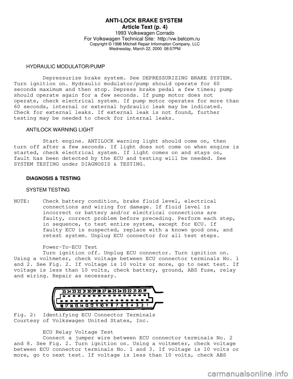
Turn ignition off. Unplug ECU connector. Turn ignition on.
Using a voltmeter, check voltage between ECU connector terminals No. 1
and 2. See Fig. 2. If voltage is 10 volts or more, go to next test. If
voltage is less than 10 volts, check battery, ground, ABS fuse, relay
and wiring. Repair as necessary.Fig. 2: Identifying ECU Connector Terminals
Courtesy of Volkswagen United States, Inc.
ECU Relay Voltage Test
Connect a jumper wire between ECU connector terminals No. 2
and 8. See Fig. 2. Turn ignition on. Using a voltmeter, check voltage
between ECU connector terminals No. 1 and 3. If voltage is 10 volts or
more, go to next test. If voltage is less than 10 volts, check ABS
Page 421 of 920
ANTI-LOCK BRAKE SYSTEM
Article Text (p. 11)
1993 Volkswagen Corrado
For Volkswagen Technical Site: http://vw.belcom.ru
Copyright © 1998 Mitchell Repair Information Company, LLC
Wednesday, March 22, 2000 08:57PM
Connect a jumper wire ECU between ECU connector terminals No.
2, 16 and 35. See Fig. 2. Depress brake pedal. Left front wheel should
be locked up. Turn ignition on. Left front wheel should rotate. If
wheel does not rotate, replace hydraulic modulator. Turn ignition off.
REMOVAL & INSTALLATION
HYDRAULIC MODULATOR/PUMP
Removal & Installation
1) Depressurize brake system. See DEPRESSURIZING BRAKE
SYSTEM. Disconnect negative battery cable. Unplug all electrical
connectors from hydraulic modulator/pump. Identify and disconnect all
hydraulic lines from hydraulic modulator/pump. Plug all line openings.
2) From inside passenger compartment, remove push rod clevis
pin. Remove hydraulic modulator/pump retaining nuts. Remove hydraulic
modulator/pump. To install, reverse removal procedure. Tighten all
fittings to specification. See TORQUE SPECIFICATIONS table. Bleed
brake system. See BLEEDING BRAKE SYSTEM.
WHEEL SPEED SENSORS
NOTE: To protect magnetic part of sensor, always leave new wheel
speed sensor in special packaging until ready for
installation.
Removal & Installation
Remove bolt retaining wheel speed sensor. Unplug connector.
Remove wheel speed sensor. To install, apply Lubricant (G-000-650) to
sensor. Install sensor, and tighten retaining bolt to 84 INCH lbs. (10
N.m).
TORQUE SPECIFICATIONS
TORQUE SPECIFICATIONS TABLEÄÄÄÄÄÄÄÄÄÄÄÄÄÄÄÄÄÄÄÄÄÄÄÄÄÄÄÄÄÄÄÄÄÄÄÄÄÄÄÄÄÄÄÄÄÄÄÄÄÄÄÄÄÄÄÄÄÄÄÄÄÄÄÄÄÄÄÄÄÄApplications Ft. Lbs. (N.m)
Brake Lines-To-Hydraulic Modulator/Pump .................... 11 (15)
Hydraulic Modulator/Pump Retaining Nuts .................... 18 (25)
INCH Lbs. (N.m)
Wheel Sensor Retaining Bolt ................................ 89 (10)
ÄÄÄÄÄÄÄÄÄÄÄÄÄÄÄÄÄÄÄÄÄÄÄÄÄÄÄÄÄÄÄÄÄÄÄÄÄÄÄÄÄÄÄÄÄÄÄÄÄÄÄÄÄÄÄÄÄÄÄÄÄÄÄÄÄÄÄÄÄÄ WIRING DIAGRAMS
Page 423 of 920
ANTI-THEFT SYSTEM
Article Text
1993 Volkswagen Corrado
For Volkswagen Technical Site: http://vw.belcom.ru
Copyright © 1998 Mitchell Repair Information Company, LLC
Wednesday, March 22, 2000 08:57PM
ARTICLE BEGINNING
1993 ACCESSORIES & EQUIPMENT
Volkswagen Anti-Theft
Volkswagen; Corrado SLC, Passat
DESCRIPTION & OPERATION
The anti-theft system monitors the radio, all doors, hood and
trunk lid position. When the anti-theft system is activated, The horn
and emergency flashers will be activated and the vehicle will not
start. The windows and sun roof (if equipped) are not monitored.
The anti-theft system has self-diagnostic capabilities that
monitor all components and wiring harness. If the system is
functioning correctly, the horn will sound briefly after front door is
locked with the key.
ANTI-THEFT CONTROL MODULE LOCATION TABLEÄÄÄÄÄÄÄÄÄÄÄÄÄÄÄÄÄÄÄÄÄÄÄÄÄÄÄÄÄÄÄÄÄÄÄÄÄÄÄÄÄÄÄÄÄÄÄÄÄÄÄÄÄÄÄÄÄÄÄÄModel Location
Corrado SLC ...................... Behind Right Kick Panel
Passat ...................... Driver Side Fuse/Relay Panel
ÄÄÄÄÄÄÄÄÄÄÄÄÄÄÄÄÄÄÄÄÄÄÄÄÄÄÄÄÄÄÄÄÄÄÄÄÄÄÄÄÄÄÄÄÄÄÄÄÄÄÄÄÄÄÄÄÄÄÄÄ TROUBLE SHOOTING
SYSTEM DOES NOT OPERATE
NOTE: Ensure battery is fully charged and all fuses are okay.
1) Ground Circuit Check
Obtain radio security code. Disconnect battery cable
terminals. Disconnect anti-theft control module 6-pin and 10-pin
wiring harness connector. See ANTI-THEFT CONTROL MODULE LOCATION
table. Connect ohmmeter negative lead to ground. Connect positive lead
to anti-theft control module 10-pin wiring harness connector terminal
No. "3" (Brown wire). If continuity is present, go to next step. If
continuity is not present, repair open circuit.
2) Power Circuit Check
Connect battery cable terminals. Connect voltmeter negative
lead to ground. Connect positive lead to anti-theft control module 6-
pin wiring harness connector terminal No. "3" (Red wire). Switch
positive lead to anti-theft control module 10-pin wiring harness
connector terminal No. "1" (Red wire). If 12 volts are present at both
terminals, go to next step. If 12 volts are not present, repair open
circuit.
3) Turn ignition on. Leave voltmeter negative lead connected
to ground. Connect positive lead to anti-theft control module 10-pin
wiring harness connector terminal No. "4" (Black wire for Corrado;