battery VOLKSWAGEN CORRADO 1993 Repair Manual
[x] Cancel search | Manufacturer: VOLKSWAGEN, Model Year: 1993, Model line: CORRADO, Model: VOLKSWAGEN CORRADO 1993Pages: 920, PDF Size: 6.92 MB
Page 70 of 920
* ELECTRICAL SYSTEM UNIFORM INSPECTION GUIDELINES *
Article Text (p. 5)
1993 Volkswagen Corrado
For Volkswagen Technical Site: http://vw.belcom.ru
Copyright © 1998 Mitchell Repair Information Company, LLC
Wednesday, March 22, 2000 08:34PM
replacement of affected components.
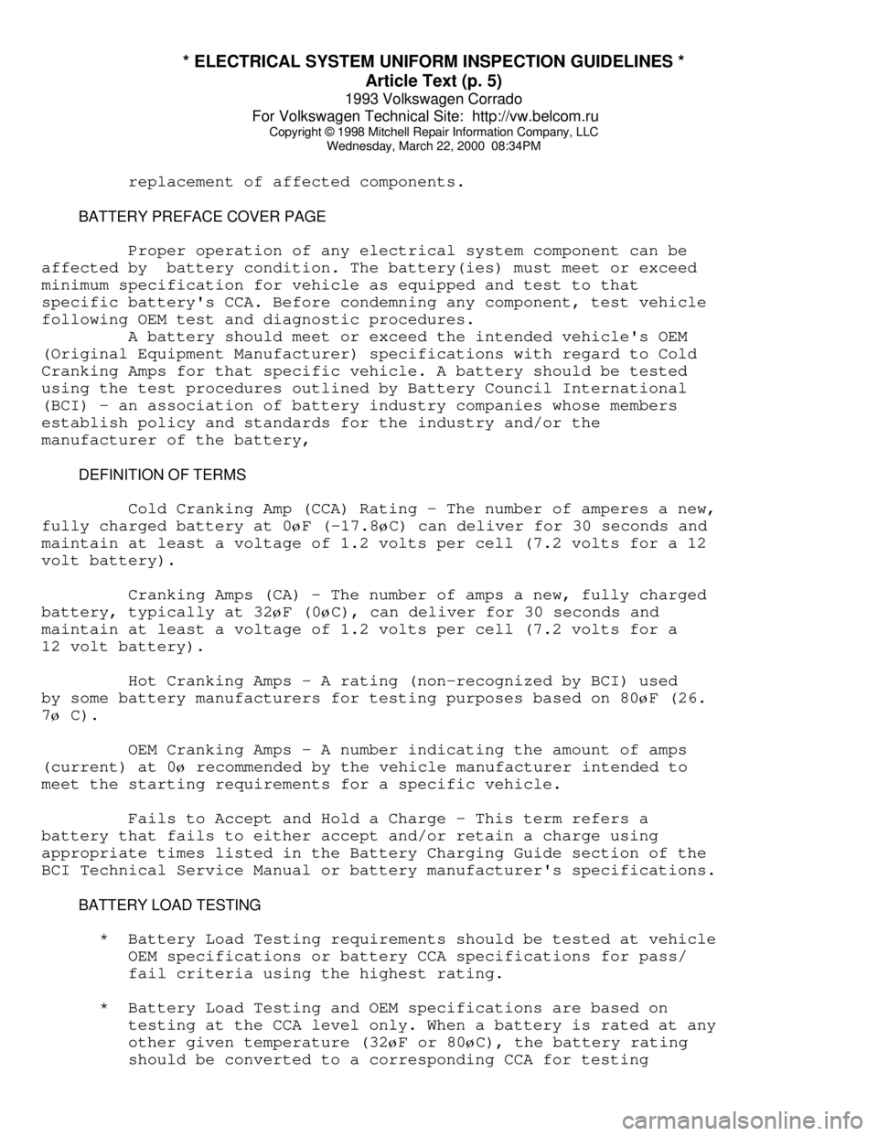
BATTERY PREFACE COVER PAGE
Proper operation of any electrical system component can be
affected by battery condition. The battery(ies) must meet or exceed
minimum specification for vehicle as equipped and test to that
specific battery's CCA. Before condemning any component, test vehicle
following OEM test and diagnostic procedures.
A battery should meet or exceed the intended vehicle's OEM
(Original Equipment Manufacturer) specifications with regard to Cold
Cranking Amps for that specific vehicle. A battery should be tested
using the test procedures outlined by Battery Council International
(BCI) - an association of battery industry companies whose members
establish policy and standards for the industry and/or the
manufacturer of the battery,
DEFINITION OF TERMS
Cold Cranking Amp (CCA) Rating - The number of amperes a new,
fully charged battery at 0øF (-17.8øC) can deliver for 30 seconds and
maintain at least a voltage of 1.2 volts per cell (7.2 volts for a 12
volt battery).
Cranking Amps (CA) - The number of amps a new, fully charged
battery, typically at 32
øF (0øC), can deliver for 30 seconds and
maintain at least a voltage of 1.2 volts per cell (7.2 volts for a
12 volt battery).
Hot Cranking Amps - A rating (non-recognized by BCI) used
by some battery manufacturers for testing purposes based on 80
øF (26.
7
ø C).
OEM Cranking Amps - A number indicating the amount of amps
(current) at 0
ø recommended by the vehicle manufacturer intended to
meet the starting requirements for a specific vehicle.
Fails to Accept and Hold a Charge - This term refers a
battery that fails to either accept and/or retain a charge using
appropriate times listed in the Battery Charging Guide section of the
BCI Technical Service Manual or battery manufacturer's specifications.
BATTERY LOAD TESTING
* Battery Load Testing requirements should be tested at vehicle
OEM specifications or battery CCA specifications for pass/
fail criteria using the highest rating.
* Battery Load Testing and OEM specifications are based on
testing at the CCA level only. When a battery is rated at any
other given temperature (32
øF or 80øC), the battery rating
should be converted to a corresponding CCA for testing
Page 71 of 920
* ELECTRICAL SYSTEM UNIFORM INSPECTION GUIDELINES *
Article Text (p. 6)
1993 Volkswagen Corrado
For Volkswagen Technical Site: http://vw.belcom.ru
Copyright © 1998 Mitchell Repair Information Company, LLC
Wednesday, March 22, 2000 08:34PM
purposes.
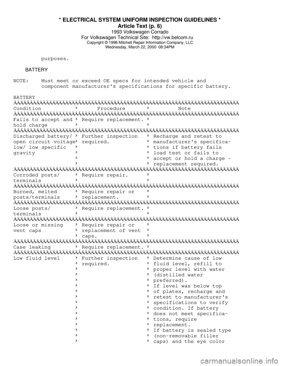
BATTERY
NOTE: Must meet or exceed OE specs for intended vehicle and
component manufacturer's specifications for specific battery.
BATTERYÄÄÄÄÄÄÄÄÄÄÄÄÄÄÄÄÄÄÄÄÂÄÄÄÄÄÄÄÄÄÄÄÄÄÄÄÄÄÄÄÄÄÄÂÄÄÄÄÄÄÄÄÄÄÄÄÄÄÄÄÄÄÄÄÄÄÄÄÄÄCondition
³ Procedure ³ Note
ÄÄÄÄÄÄÄÄÄÄÄÄÄÄÄÄÄÄÄÄÅÄÄÄÄÄÄÄÄÄÄÄÄÄÄÄÄÄÄÄÄÄÄÅÄÄÄÄÄÄÄÄÄÄÄÄÄÄÄÄÄÄÄÄÄÄÄÄÄÄFails to accept and
³ Require replacement. ³hold charge
³ ³
ÄÄÄÄÄÄÄÄÄÄÄÄÄÄÄÄÄÄÄÄÅÄÄÄÄÄÄÄÄÄÄÄÄÄÄÄÄÄÄÄÄÄÄÅÄÄÄÄÄÄÄÄÄÄÄÄÄÄÄÄÄÄÄÄÄÄÄÄÄÄDischarged battery/
³ Further inspection ³ Recharge and retest to
open circuit voltage
³ required. ³ manufacturer's specifica-
low/ low specific
³ ³ tions if battery fails
gravity
³ ³ load test or fails to
³ ³ accept or hold a charge -
³ ³ replacement required.
ÄÄÄÄÄÄÄÄÄÄÄÄÄÄÄÄÄÄÄÄÅÄÄÄÄÄÄÄÄÄÄÄÄÄÄÄÄÄÄÄÄÄÄÅÄÄÄÄÄÄÄÄÄÄÄÄÄÄÄÄÄÄÄÄÄÄÄÄÄÄCorroded posts/
³ Require repair. ³terminals
³ ³
ÄÄÄÄÄÄÄÄÄÄÄÄÄÄÄÄÄÄÄÄÅÄÄÄÄÄÄÄÄÄÄÄÄÄÄÄÄÄÄÄÄÄÄÅÄÄÄÄÄÄÄÄÄÄÄÄÄÄÄÄÄÄÄÄÄÄÄÄÄÄBurned, melted
³ Require repair or ³posts/terminals
³ replacement. ³
ÄÄÄÄÄÄÄÄÄÄÄÄÄÄÄÄÄÄÄÄÅÄÄÄÄÄÄÄÄÄÄÄÄÄÄÄÄÄÄÄÄÄÄÅÄÄÄÄÄÄÄÄÄÄÄÄÄÄÄÄÄÄÄÄÄÄÄÄÄÄLoose posts/
³ Require replacement. ³terminals
³ ³
ÄÄÄÄÄÄÄÄÄÄÄÄÄÄÄÄÄÄÄÄÅÄÄÄÄÄÄÄÄÄÄÄÄÄÄÄÄÄÄÄÄÄÄÅÄÄÄÄÄÄÄÄÄÄÄÄÄÄÄÄÄÄÄÄÄÄÄÄÄÄLoose or missing
³ Require repair or ³vent caps
³ replacement of vent ³
³ caps. ³
ÄÄÄÄÄÄÄÄÄÄÄÄÄÄÄÄÄÄÄÄÅÄÄÄÄÄÄÄÄÄÄÄÄÄÄÄÄÄÄÄÄÄÄÅÄÄÄÄÄÄÄÄÄÄÄÄÄÄÄÄÄÄÄÄÄÄÄÄÄÄCase leaking
³ Require replacement. ³
ÄÄÄÄÄÄÄÄÄÄÄÄÄÄÄÄÄÄÄÄÅÄÄÄÄÄÄÄÄÄÄÄÄÄÄÄÄÄÄÄÄÄÄÅÄÄÄÄÄÄÄÄÄÄÄÄÄÄÄÄÄÄÄÄÄÄÄÄÄÄLow fluid level
³ Further inspection ³ Determine cause of low
³ required. ³ fluid level, refill to
³ ³ proper level with water
³ ³ (distilled water
³ ³ preferred).
³ ³ If level was below top
³ ³ of plates, recharge and
³ ³ retest to manufacturer's
³ ³ specifications to verify
³ ³ condition. If battery
³ ³ does not meet specifica-
³ ³ tions, require
³ ³ replacement.
³ ³ If battery is sealed type
³ ³ (non-removable filler
³ ³ caps) and the eye color
Page 72 of 920
* ELECTRICAL SYSTEM UNIFORM INSPECTION GUIDELINES *
Article Text (p. 7)
1993 Volkswagen Corrado
For Volkswagen Technical Site: http://vw.belcom.ru
Copyright © 1998 Mitchell Repair Information Company, LLC
Wednesday, March 22, 2000 08:34PM
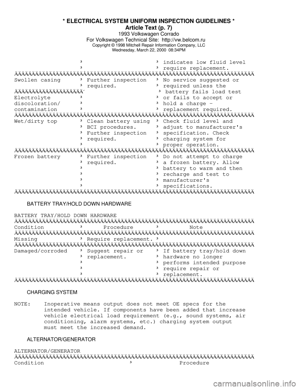
³ ³ indicates low fluid level
³ ³ require replacement.
ÄÄÄÄÄÄÄÄÄÄÄÄÄÄÄÄÄÄÄÄÅÄÄÄÄÄÄÄÄÄÄÄÄÄÄÄÄÄÄÄÄÄÄÅÄÄÄÄÄÄÄÄÄÄÄÄÄÄÄÄÄÄÄÄÄÄÄÄÄÄSwollen casing
³ Further inspection ³ No service suggested or
³ required. ³ required unless the
ÄÄÄÄÄÄÄÄÄÄÄÄÄÄÄÄÄÄÄÄ´ ³ battery fails load test
Electrolyte
³ ³ or fails to accept or
discoloration/
³ ³ hold a charge -
contamination
³ ³ replacement required.
ÄÄÄÄÄÄÄÄÄÄÄÄÄÄÄÄÄÄÄÄÅÄÄÄÄÄÄÄÄÄÄÄÄÄÄÄÄÄÄÄÄÄÄÅÄÄÄÄÄÄÄÄÄÄÄÄÄÄÄÄÄÄÄÄÄÄÄÄÄÄWet/dirty top
³ Clean battery using ³ Check fluid level and
³ BCI procedures. ³ adjust to manufacturer's
³ Further inspection ³ specification. Check
³ required. ³ charging system for
³ ³ proper operation.
ÄÄÄÄÄÄÄÄÄÄÄÄÄÄÄÄÄÄÄÄÅÄÄÄÄÄÄÄÄÄÄÄÄÄÄÄÄÄÄÄÄÄÄÅÄÄÄÄÄÄÄÄÄÄÄÄÄÄÄÄÄÄÄÄÄÄÄÄÄÄFrozen battery
³ Further inspection ³ Do not attempt to charge
³ required. ³ a frozen battery. Allow
³ ³ battery to warm and then
³ ³ recharge and test to
³ ³ manufacturer's
³ ³ specifications.
ÄÄÄÄÄÄÄÄÄÄÄÄÄÄÄÄÄÄÄÄÁÄÄÄÄÄÄÄÄÄÄÄÄÄÄÄÄÄÄÄÄÄÄÁÄÄÄÄÄÄÄÄÄÄÄÄÄÄÄÄÄÄÄÄÄÄÄÄÄÄ BATTERY TRAY/HOLD DOWN HARDWARE
BATTERY TRAY/HOLD DOWN HARDWARE
ÄÄÄÄÄÄÄÄÄÄÄÄÄÄÄÄÄÄÄÄÂÄÄÄÄÄÄÄÄÄÄÄÄÄÄÄÄÄÄÄÄÄÄÂÄÄÄÄÄÄÄÄÄÄÄÄÄÄÄÄÄÄÄÄÄÄÄÄÄÄCondition
³ Procedure ³ Note
ÄÄÄÄÄÄÄÄÄÄÄÄÄÄÄÄÄÄÄÄÅÄÄÄÄÄÄÄÄÄÄÄÄÄÄÄÄÄÄÄÄÄÄÅÄÄÄÄÄÄÄÄÄÄÄÄÄÄÄÄÄÄÄÄÄÄÄÄÄÄMissing
³ Require replacement. ³
ÄÄÄÄÄÄÄÄÄÄÄÄÄÄÄÄÄÄÄÄÅÄÄÄÄÄÄÄÄÄÄÄÄÄÄÄÄÄÄÄÄÄÄÅÄÄÄÄÄÄÄÄÄÄÄÄÄÄÄÄÄÄÄÄÄÄÄÄÄÄDamaged/corroded
³ Suggest repair or ³ If battery tray/hold down
³ replacement. ³ hardware no longer
³ ³ performs intended purpose
³ ³ require repair or
³ ³ replacement.
ÄÄÄÄÄÄÄÄÄÄÄÄÄÄÄÄÄÄÄÄÁÄÄÄÄÄÄÄÄÄÄÄÄÄÄÄÄÄÄÄÄÄÄÁÄÄÄÄÄÄÄÄÄÄÄÄÄÄÄÄÄÄÄÄÄÄÄÄÄÄ CHARGING SYSTEM
NOTE: Inoperative means output does not meet OE specs for the
intended vehicle. If components have been added that increase
vehicle electrical load requirement (e.g., sound systems, air
conditioning, alarm systems, etc.) charging system output
must meet the increased demand.
ALTERNATOR/GENERATOR
ALTERNATOR/GENERATOR
ÄÄÄÄÄÄÄÄÄÄÄÄÄÄÄÄÄÄÄÄÄÄÄÄÄÄÄÄÄÄÄÄÄÄÄÂÄÄÄÄÄÄÄÄÄÄÄÄÄÄÄÄÄÄÄÄÄÄÄÄÄÄÄÄÄÄÄÄÄÄCondition
³ Procedure
Page 79 of 920
* ELECTRICAL SYSTEM UNIFORM INSPECTION GUIDELINES *
Article Text (p. 14)
1993 Volkswagen Corrado
For Volkswagen Technical Site: http://vw.belcom.ru
Copyright © 1998 Mitchell Repair Information Company, LLC
Wednesday, March 22, 2000 08:34PM
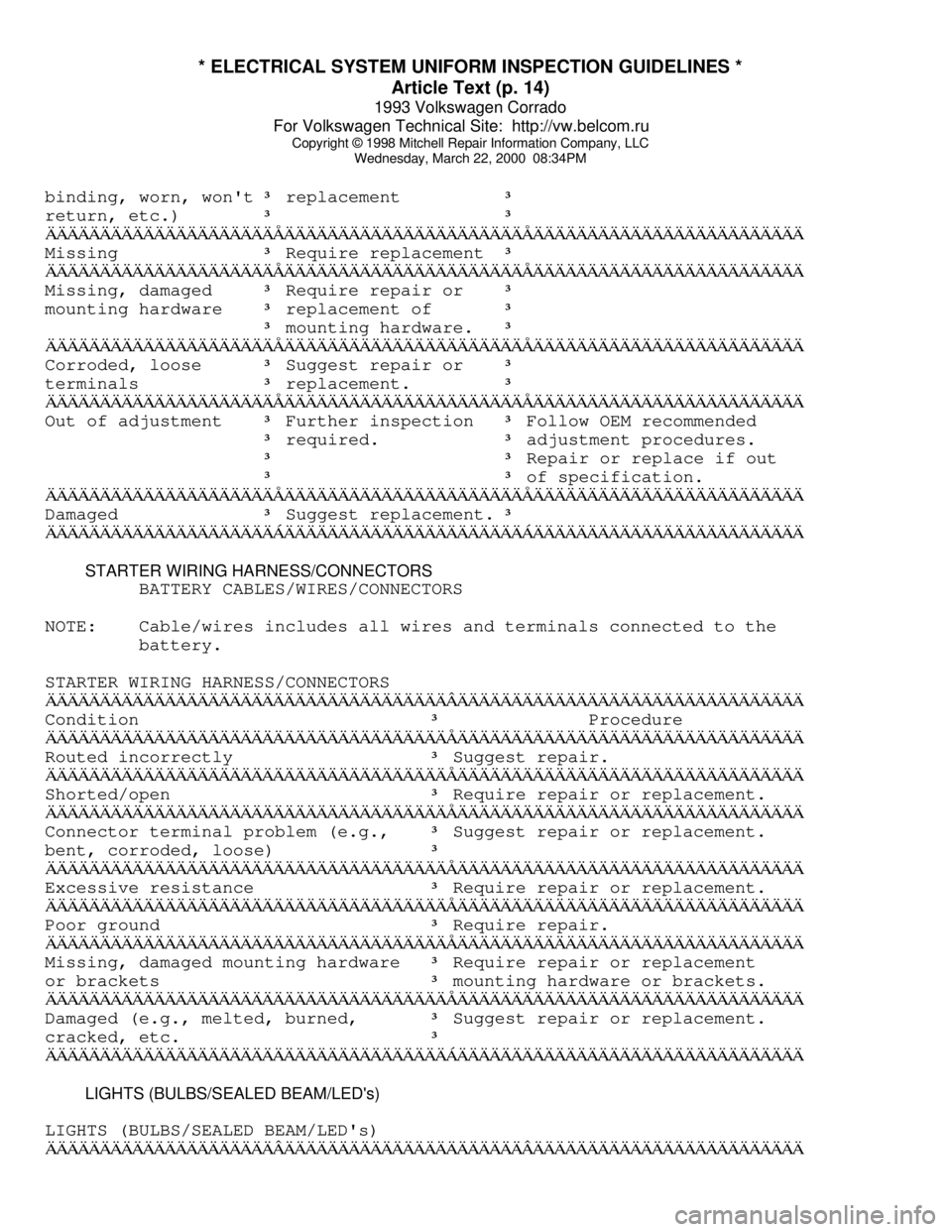
binding, worn, won't ³ replacement ³return, etc.)
³ ³
ÄÄÄÄÄÄÄÄÄÄÄÄÄÄÄÄÄÄÄÄÄÅÄÄÄÄÄÄÄÄÄÄÄÄÄÄÄÄÄÄÄÄÄÄÅÄÄÄÄÄÄÄÄÄÄÄÄÄÄÄÄÄÄÄÄÄÄÄÄÄMissing
³ Require replacement ³
ÄÄÄÄÄÄÄÄÄÄÄÄÄÄÄÄÄÄÄÄÄÅÄÄÄÄÄÄÄÄÄÄÄÄÄÄÄÄÄÄÄÄÄÄÅÄÄÄÄÄÄÄÄÄÄÄÄÄÄÄÄÄÄÄÄÄÄÄÄÄMissing, damaged
³ Require repair or ³mounting hardware
³ replacement of ³
³ mounting hardware. ³
ÄÄÄÄÄÄÄÄÄÄÄÄÄÄÄÄÄÄÄÄÄÅÄÄÄÄÄÄÄÄÄÄÄÄÄÄÄÄÄÄÄÄÄÄÅÄÄÄÄÄÄÄÄÄÄÄÄÄÄÄÄÄÄÄÄÄÄÄÄÄCorroded, loose
³ Suggest repair or ³terminals
³ replacement. ³
ÄÄÄÄÄÄÄÄÄÄÄÄÄÄÄÄÄÄÄÄÄÅÄÄÄÄÄÄÄÄÄÄÄÄÄÄÄÄÄÄÄÄÄÄÅÄÄÄÄÄÄÄÄÄÄÄÄÄÄÄÄÄÄÄÄÄÄÄÄÄOut of adjustment
³ Further inspection ³ Follow OEM recommended
³ required. ³ adjustment procedures.
³ ³ Repair or replace if out
³ ³ of specification.
ÄÄÄÄÄÄÄÄÄÄÄÄÄÄÄÄÄÄÄÄÄÅÄÄÄÄÄÄÄÄÄÄÄÄÄÄÄÄÄÄÄÄÄÄÅÄÄÄÄÄÄÄÄÄÄÄÄÄÄÄÄÄÄÄÄÄÄÄÄÄDamaged
³ Suggest replacement. ³
ÄÄÄÄÄÄÄÄÄÄÄÄÄÄÄÄÄÄÄÄÄÁÄÄÄÄÄÄÄÄÄÄÄÄÄÄÄÄÄÄÄÄÄÄÁÄÄÄÄÄÄÄÄÄÄÄÄÄÄÄÄÄÄÄÄÄÄÄÄÄ STARTER WIRING HARNESS/CONNECTORS
BATTERY CABLES/WIRES/CONNECTORS
NOTE: Cable/wires includes all wires and terminals connected to the
battery.
STARTER WIRING HARNESS/CONNECTORS
ÄÄÄÄÄÄÄÄÄÄÄÄÄÄÄÄÄÄÄÄÄÄÄÄÄÄÄÄÄÄÄÄÄÄÄÄÄÂÄÄÄÄÄÄÄÄÄÄÄÄÄÄÄÄÄÄÄÄÄÄÄÄÄÄÄÄÄÄÄÄCondition
³ Procedure
ÄÄÄÄÄÄÄÄÄÄÄÄÄÄÄÄÄÄÄÄÄÄÄÄÄÄÄÄÄÄÄÄÄÄÄÄÄÅÄÄÄÄÄÄÄÄÄÄÄÄÄÄÄÄÄÄÄÄÄÄÄÄÄÄÄÄÄÄÄÄRouted incorrectly
³ Suggest repair.
ÄÄÄÄÄÄÄÄÄÄÄÄÄÄÄÄÄÄÄÄÄÄÄÄÄÄÄÄÄÄÄÄÄÄÄÄÄÅÄÄÄÄÄÄÄÄÄÄÄÄÄÄÄÄÄÄÄÄÄÄÄÄÄÄÄÄÄÄÄÄShorted/open
³ Require repair or replacement.
ÄÄÄÄÄÄÄÄÄÄÄÄÄÄÄÄÄÄÄÄÄÄÄÄÄÄÄÄÄÄÄÄÄÄÄÄÄÅÄÄÄÄÄÄÄÄÄÄÄÄÄÄÄÄÄÄÄÄÄÄÄÄÄÄÄÄÄÄÄÄConnector terminal problem (e.g.,
³ Suggest repair or replacement.
bent, corroded, loose)
³
ÄÄÄÄÄÄÄÄÄÄÄÄÄÄÄÄÄÄÄÄÄÄÄÄÄÄÄÄÄÄÄÄÄÄÄÄÄÅÄÄÄÄÄÄÄÄÄÄÄÄÄÄÄÄÄÄÄÄÄÄÄÄÄÄÄÄÄÄÄÄExcessive resistance
³ Require repair or replacement.
ÄÄÄÄÄÄÄÄÄÄÄÄÄÄÄÄÄÄÄÄÄÄÄÄÄÄÄÄÄÄÄÄÄÄÄÄÄÅÄÄÄÄÄÄÄÄÄÄÄÄÄÄÄÄÄÄÄÄÄÄÄÄÄÄÄÄÄÄÄÄPoor ground
³ Require repair.
ÄÄÄÄÄÄÄÄÄÄÄÄÄÄÄÄÄÄÄÄÄÄÄÄÄÄÄÄÄÄÄÄÄÄÄÄÄÅÄÄÄÄÄÄÄÄÄÄÄÄÄÄÄÄÄÄÄÄÄÄÄÄÄÄÄÄÄÄÄÄMissing, damaged mounting hardware
³ Require repair or replacement
or brackets
³ mounting hardware or brackets.
ÄÄÄÄÄÄÄÄÄÄÄÄÄÄÄÄÄÄÄÄÄÄÄÄÄÄÄÄÄÄÄÄÄÄÄÄÄÅÄÄÄÄÄÄÄÄÄÄÄÄÄÄÄÄÄÄÄÄÄÄÄÄÄÄÄÄÄÄÄÄDamaged (e.g., melted, burned,
³ Suggest repair or replacement.
cracked, etc.
³
ÄÄÄÄÄÄÄÄÄÄÄÄÄÄÄÄÄÄÄÄÄÄÄÄÄÄÄÄÄÄÄÄÄÄÄÄÄÁÄÄÄÄÄÄÄÄÄÄÄÄÄÄÄÄÄÄÄÄÄÄÄÄÄÄÄÄÄÄÄÄ LIGHTS (BULBS/SEALED BEAM/LED's)
LIGHTS (BULBS/SEALED BEAM/LED's)
ÄÄÄÄÄÄÄÄÄÄÄÄÄÄÄÄÄÄÄÄÄÂÄÄÄÄÄÄÄÄÄÄÄÄÄÄÄÄÄÄÄÄÄÄÂÄÄÄÄÄÄÄÄÄÄÄÄÄÄÄÄÄÄÄÄÄÄÄÄÄ
Page 118 of 920
* ENGINE SYSTEMS UNIFORM INSPECTION GUIDELINES *
Article Text (p. 21)
1993 Volkswagen Corrado
For Volkswagen Technical Site: http://vw.belcom.ru
Copyright © 1998 Mitchell Repair Information Company, LLC
Wednesday, March 22, 2000 08:41PM
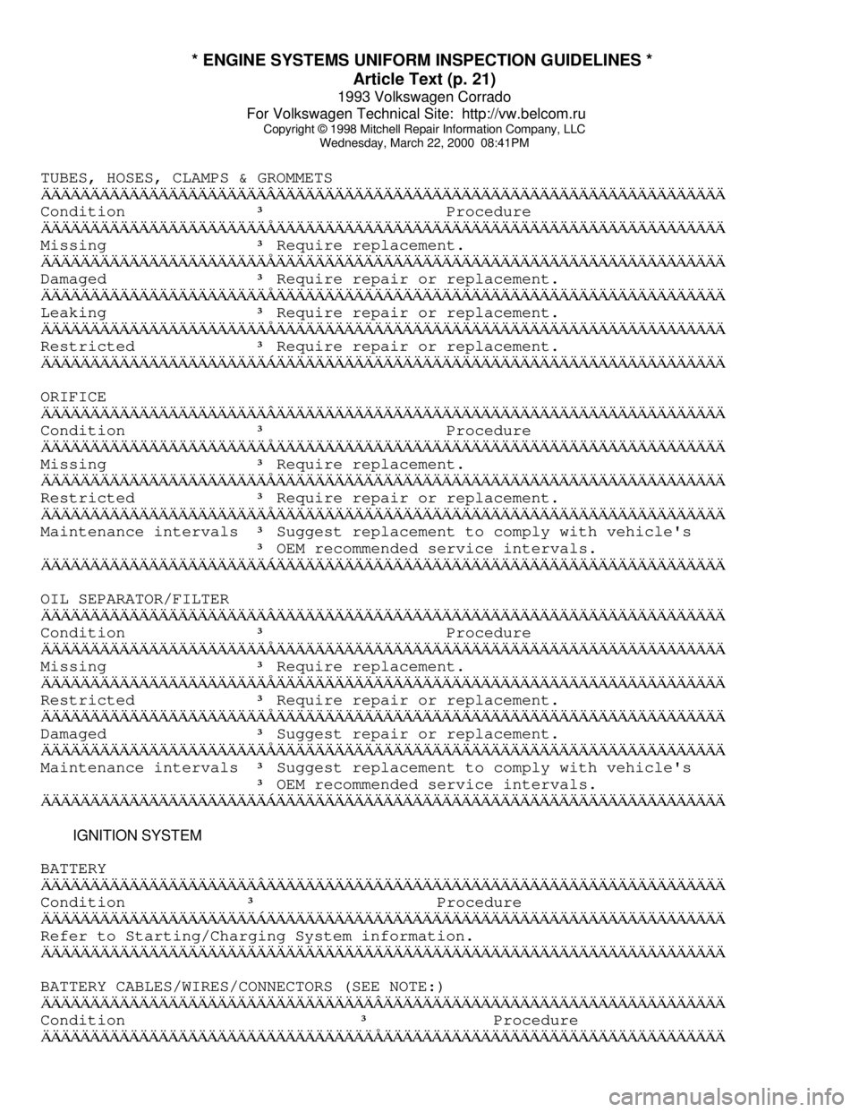
TUBES, HOSES, CLAMPS & GROMMETSÄÄÄÄÄÄÄÄÄÄÄÄÄÄÄÄÄÄÄÄÄÄÄÂÄÄÄÄÄÄÄÄÄÄÄÄÄÄÄÄÄÄÄÄÄÄÄÄÄÄÄÄÄÄÄÄÄÄÄÄÄÄÄÄÄÄÄÄÄÄCondition
³ Procedure
ÄÄÄÄÄÄÄÄÄÄÄÄÄÄÄÄÄÄÄÄÄÄÄÅÄÄÄÄÄÄÄÄÄÄÄÄÄÄÄÄÄÄÄÄÄÄÄÄÄÄÄÄÄÄÄÄÄÄÄÄÄÄÄÄÄÄÄÄÄÄMissing
³ Require replacement.
ÄÄÄÄÄÄÄÄÄÄÄÄÄÄÄÄÄÄÄÄÄÄÄÅÄÄÄÄÄÄÄÄÄÄÄÄÄÄÄÄÄÄÄÄÄÄÄÄÄÄÄÄÄÄÄÄÄÄÄÄÄÄÄÄÄÄÄÄÄÄDamaged
³ Require repair or replacement.
ÄÄÄÄÄÄÄÄÄÄÄÄÄÄÄÄÄÄÄÄÄÄÄÅÄÄÄÄÄÄÄÄÄÄÄÄÄÄÄÄÄÄÄÄÄÄÄÄÄÄÄÄÄÄÄÄÄÄÄÄÄÄÄÄÄÄÄÄÄÄLeaking
³ Require repair or replacement.
ÄÄÄÄÄÄÄÄÄÄÄÄÄÄÄÄÄÄÄÄÄÄÄÅÄÄÄÄÄÄÄÄÄÄÄÄÄÄÄÄÄÄÄÄÄÄÄÄÄÄÄÄÄÄÄÄÄÄÄÄÄÄÄÄÄÄÄÄÄÄRestricted
³ Require repair or replacement.
ÄÄÄÄÄÄÄÄÄÄÄÄÄÄÄÄÄÄÄÄÄÄÄÁÄÄÄÄÄÄÄÄÄÄÄÄÄÄÄÄÄÄÄÄÄÄÄÄÄÄÄÄÄÄÄÄÄÄÄÄÄÄÄÄÄÄÄÄÄÄORIFICE
ÄÄÄÄÄÄÄÄÄÄÄÄÄÄÄÄÄÄÄÄÄÄÄÂÄÄÄÄÄÄÄÄÄÄÄÄÄÄÄÄÄÄÄÄÄÄÄÄÄÄÄÄÄÄÄÄÄÄÄÄÄÄÄÄÄÄÄÄÄÄCondition
³ Procedure
ÄÄÄÄÄÄÄÄÄÄÄÄÄÄÄÄÄÄÄÄÄÄÄÅÄÄÄÄÄÄÄÄÄÄÄÄÄÄÄÄÄÄÄÄÄÄÄÄÄÄÄÄÄÄÄÄÄÄÄÄÄÄÄÄÄÄÄÄÄÄMissing
³ Require replacement.
ÄÄÄÄÄÄÄÄÄÄÄÄÄÄÄÄÄÄÄÄÄÄÄÅÄÄÄÄÄÄÄÄÄÄÄÄÄÄÄÄÄÄÄÄÄÄÄÄÄÄÄÄÄÄÄÄÄÄÄÄÄÄÄÄÄÄÄÄÄÄRestricted
³ Require repair or replacement.
ÄÄÄÄÄÄÄÄÄÄÄÄÄÄÄÄÄÄÄÄÄÄÄÅÄÄÄÄÄÄÄÄÄÄÄÄÄÄÄÄÄÄÄÄÄÄÄÄÄÄÄÄÄÄÄÄÄÄÄÄÄÄÄÄÄÄÄÄÄÄMaintenance intervals
³ Suggest replacement to comply with vehicle's
³ OEM recommended service intervals.
ÄÄÄÄÄÄÄÄÄÄÄÄÄÄÄÄÄÄÄÄÄÄÄÁÄÄÄÄÄÄÄÄÄÄÄÄÄÄÄÄÄÄÄÄÄÄÄÄÄÄÄÄÄÄÄÄÄÄÄÄÄÄÄÄÄÄÄÄÄÄOIL SEPARATOR/FILTER
ÄÄÄÄÄÄÄÄÄÄÄÄÄÄÄÄÄÄÄÄÄÄÄÂÄÄÄÄÄÄÄÄÄÄÄÄÄÄÄÄÄÄÄÄÄÄÄÄÄÄÄÄÄÄÄÄÄÄÄÄÄÄÄÄÄÄÄÄÄÄCondition
³ Procedure
ÄÄÄÄÄÄÄÄÄÄÄÄÄÄÄÄÄÄÄÄÄÄÄÅÄÄÄÄÄÄÄÄÄÄÄÄÄÄÄÄÄÄÄÄÄÄÄÄÄÄÄÄÄÄÄÄÄÄÄÄÄÄÄÄÄÄÄÄÄÄMissing
³ Require replacement.
ÄÄÄÄÄÄÄÄÄÄÄÄÄÄÄÄÄÄÄÄÄÄÄÅÄÄÄÄÄÄÄÄÄÄÄÄÄÄÄÄÄÄÄÄÄÄÄÄÄÄÄÄÄÄÄÄÄÄÄÄÄÄÄÄÄÄÄÄÄÄRestricted
³ Require repair or replacement.
ÄÄÄÄÄÄÄÄÄÄÄÄÄÄÄÄÄÄÄÄÄÄÄÅÄÄÄÄÄÄÄÄÄÄÄÄÄÄÄÄÄÄÄÄÄÄÄÄÄÄÄÄÄÄÄÄÄÄÄÄÄÄÄÄÄÄÄÄÄÄDamaged
³ Suggest repair or replacement.
ÄÄÄÄÄÄÄÄÄÄÄÄÄÄÄÄÄÄÄÄÄÄÄÅÄÄÄÄÄÄÄÄÄÄÄÄÄÄÄÄÄÄÄÄÄÄÄÄÄÄÄÄÄÄÄÄÄÄÄÄÄÄÄÄÄÄÄÄÄÄMaintenance intervals
³ Suggest replacement to comply with vehicle's
³ OEM recommended service intervals.
ÄÄÄÄÄÄÄÄÄÄÄÄÄÄÄÄÄÄÄÄÄÄÄÁÄÄÄÄÄÄÄÄÄÄÄÄÄÄÄÄÄÄÄÄÄÄÄÄÄÄÄÄÄÄÄÄÄÄÄÄÄÄÄÄÄÄÄÄÄÄ IGNITION SYSTEM
BATTERY
ÄÄÄÄÄÄÄÄÄÄÄÄÄÄÄÄÄÄÄÄÄÄÂÄÄÄÄÄÄÄÄÄÄÄÄÄÄÄÄÄÄÄÄÄÄÄÄÄÄÄÄÄÄÄÄÄÄÄÄÄÄÄÄÄÄÄÄÄÄÄCondition
³ Procedure
ÄÄÄÄÄÄÄÄÄÄÄÄÄÄÄÄÄÄÄÄÄÄÁÄÄÄÄÄÄÄÄÄÄÄÄÄÄÄÄÄÄÄÄÄÄÄÄÄÄÄÄÄÄÄÄÄÄÄÄÄÄÄÄÄÄÄÄÄÄÄRefer to Starting/Charging System information.
ÄÄÄÄÄÄÄÄÄÄÄÄÄÄÄÄÄÄÄÄÄÄÄÄÄÄÄÄÄÄÄÄÄÄÄÄÄÄÄÄÄÄÄÄÄÄÄÄÄÄÄÄÄÄÄÄÄÄÄÄÄÄÄÄÄÄÄÄÄÄBATTERY CABLES/WIRES/CONNECTORS (SEE NOTE:)
ÄÄÄÄÄÄÄÄÄÄÄÄÄÄÄÄÄÄÄÄÄÄÄÄÄÄÄÄÄÄÄÄÄÄÂÄÄÄÄÄÄÄÄÄÄÄÄÄÄÄÄÄÄÄÄÄÄÄÄÄÄÄÄÄÄÄÄÄÄÄCondition
³ Procedure
ÄÄÄÄÄÄÄÄÄÄÄÄÄÄÄÄÄÄÄÄÄÄÄÄÄÄÄÄÄÄÄÄÄÄÅÄÄÄÄÄÄÄÄÄÄÄÄÄÄÄÄÄÄÄÄÄÄÄÄÄÄÄÄÄÄÄÄÄÄÄ
Page 119 of 920
* ENGINE SYSTEMS UNIFORM INSPECTION GUIDELINES *
Article Text (p. 22)
1993 Volkswagen Corrado
For Volkswagen Technical Site: http://vw.belcom.ru
Copyright © 1998 Mitchell Repair Information Company, LLC
Wednesday, March 22, 2000 08:41PM
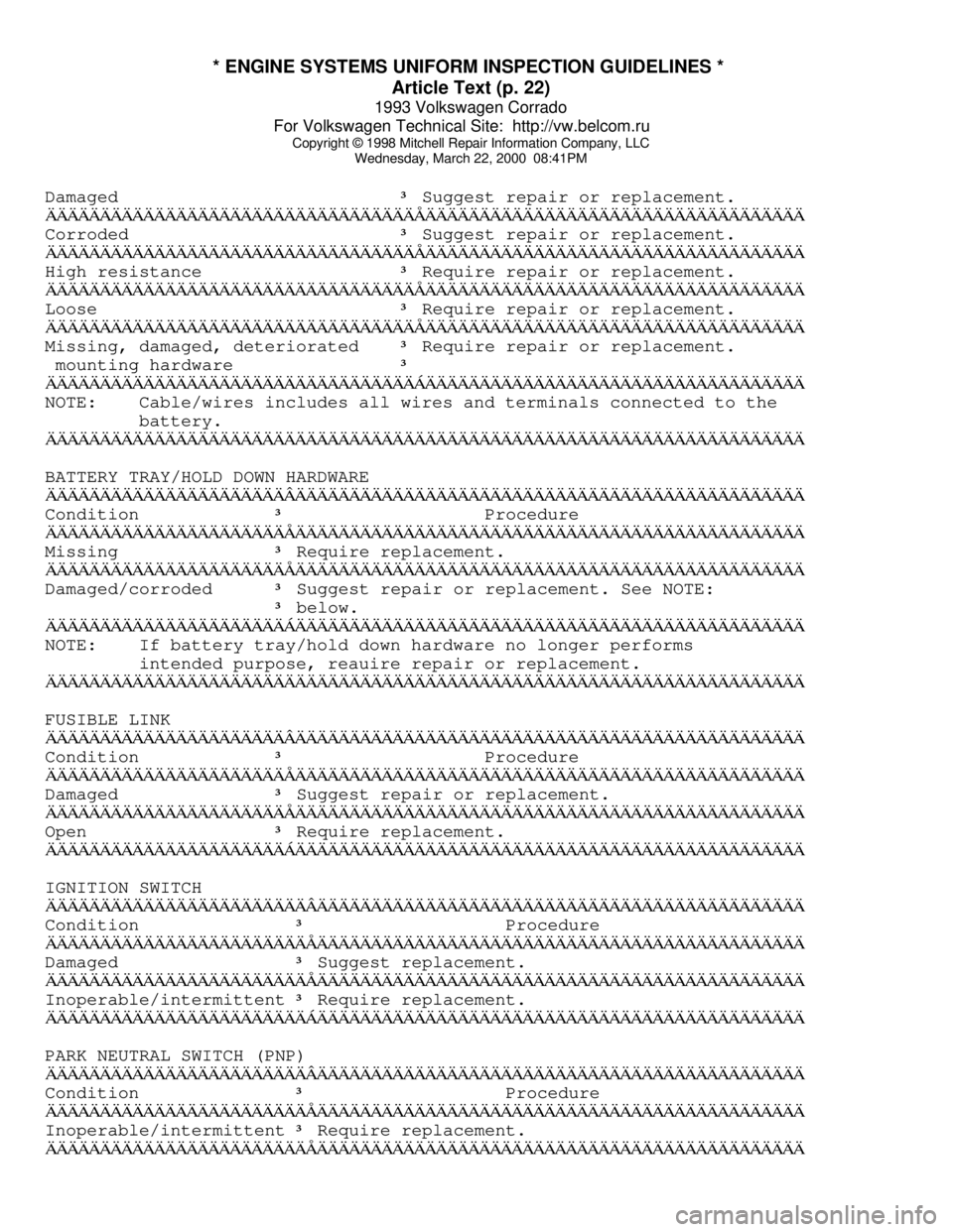
Damaged ³ Suggest repair or replacement.
ÄÄÄÄÄÄÄÄÄÄÄÄÄÄÄÄÄÄÄÄÄÄÄÄÄÄÄÄÄÄÄÄÄÄÅÄÄÄÄÄÄÄÄÄÄÄÄÄÄÄÄÄÄÄÄÄÄÄÄÄÄÄÄÄÄÄÄÄÄÄCorroded
³ Suggest repair or replacement.
ÄÄÄÄÄÄÄÄÄÄÄÄÄÄÄÄÄÄÄÄÄÄÄÄÄÄÄÄÄÄÄÄÄÄÅÄÄÄÄÄÄÄÄÄÄÄÄÄÄÄÄÄÄÄÄÄÄÄÄÄÄÄÄÄÄÄÄÄÄÄHigh resistance
³ Require repair or replacement.
ÄÄÄÄÄÄÄÄÄÄÄÄÄÄÄÄÄÄÄÄÄÄÄÄÄÄÄÄÄÄÄÄÄÄÅÄÄÄÄÄÄÄÄÄÄÄÄÄÄÄÄÄÄÄÄÄÄÄÄÄÄÄÄÄÄÄÄÄÄÄLoose
³ Require repair or replacement.
ÄÄÄÄÄÄÄÄÄÄÄÄÄÄÄÄÄÄÄÄÄÄÄÄÄÄÄÄÄÄÄÄÄÄÅÄÄÄÄÄÄÄÄÄÄÄÄÄÄÄÄÄÄÄÄÄÄÄÄÄÄÄÄÄÄÄÄÄÄÄMissing, damaged, deteriorated
³ Require repair or replacement.
mounting hardware
³
ÄÄÄÄÄÄÄÄÄÄÄÄÄÄÄÄÄÄÄÄÄÄÄÄÄÄÄÄÄÄÄÄÄÄÁÄÄÄÄÄÄÄÄÄÄÄÄÄÄÄÄÄÄÄÄÄÄÄÄÄÄÄÄÄÄÄÄÄÄÄNOTE: Cable/wires includes all wires and terminals connected to the
battery.
ÄÄÄÄÄÄÄÄÄÄÄÄÄÄÄÄÄÄÄÄÄÄÄÄÄÄÄÄÄÄÄÄÄÄÄÄÄÄÄÄÄÄÄÄÄÄÄÄÄÄÄÄÄÄÄÄÄÄÄÄÄÄÄÄÄÄÄÄÄÄBATTERY TRAY/HOLD DOWN HARDWARE
ÄÄÄÄÄÄÄÄÄÄÄÄÄÄÄÄÄÄÄÄÄÄÂÄÄÄÄÄÄÄÄÄÄÄÄÄÄÄÄÄÄÄÄÄÄÄÄÄÄÄÄÄÄÄÄÄÄÄÄÄÄÄÄÄÄÄÄÄÄÄCondition
³ Procedure
ÄÄÄÄÄÄÄÄÄÄÄÄÄÄÄÄÄÄÄÄÄÄÅÄÄÄÄÄÄÄÄÄÄÄÄÄÄÄÄÄÄÄÄÄÄÄÄÄÄÄÄÄÄÄÄÄÄÄÄÄÄÄÄÄÄÄÄÄÄÄMissing
³ Require replacement.
ÄÄÄÄÄÄÄÄÄÄÄÄÄÄÄÄÄÄÄÄÄÄÅÄÄÄÄÄÄÄÄÄÄÄÄÄÄÄÄÄÄÄÄÄÄÄÄÄÄÄÄÄÄÄÄÄÄÄÄÄÄÄÄÄÄÄÄÄÄÄDamaged/corroded
³ Suggest repair or replacement. See NOTE:
³ below.
ÄÄÄÄÄÄÄÄÄÄÄÄÄÄÄÄÄÄÄÄÄÄÁÄÄÄÄÄÄÄÄÄÄÄÄÄÄÄÄÄÄÄÄÄÄÄÄÄÄÄÄÄÄÄÄÄÄÄÄÄÄÄÄÄÄÄÄÄÄÄNOTE: If battery tray/hold down hardware no longer performs
intended purpose, reauire repair or replacement.
ÄÄÄÄÄÄÄÄÄÄÄÄÄÄÄÄÄÄÄÄÄÄÄÄÄÄÄÄÄÄÄÄÄÄÄÄÄÄÄÄÄÄÄÄÄÄÄÄÄÄÄÄÄÄÄÄÄÄÄÄÄÄÄÄÄÄÄÄÄÄFUSIBLE LINK
ÄÄÄÄÄÄÄÄÄÄÄÄÄÄÄÄÄÄÄÄÄÄÂÄÄÄÄÄÄÄÄÄÄÄÄÄÄÄÄÄÄÄÄÄÄÄÄÄÄÄÄÄÄÄÄÄÄÄÄÄÄÄÄÄÄÄÄÄÄÄCondition
³ Procedure
ÄÄÄÄÄÄÄÄÄÄÄÄÄÄÄÄÄÄÄÄÄÄÅÄÄÄÄÄÄÄÄÄÄÄÄÄÄÄÄÄÄÄÄÄÄÄÄÄÄÄÄÄÄÄÄÄÄÄÄÄÄÄÄÄÄÄÄÄÄÄDamaged
³ Suggest repair or replacement.
ÄÄÄÄÄÄÄÄÄÄÄÄÄÄÄÄÄÄÄÄÄÄÅÄÄÄÄÄÄÄÄÄÄÄÄÄÄÄÄÄÄÄÄÄÄÄÄÄÄÄÄÄÄÄÄÄÄÄÄÄÄÄÄÄÄÄÄÄÄÄOpen
³ Require replacement.
ÄÄÄÄÄÄÄÄÄÄÄÄÄÄÄÄÄÄÄÄÄÄÁÄÄÄÄÄÄÄÄÄÄÄÄÄÄÄÄÄÄÄÄÄÄÄÄÄÄÄÄÄÄÄÄÄÄÄÄÄÄÄÄÄÄÄÄÄÄÄIGNITION SWITCH
ÄÄÄÄÄÄÄÄÄÄÄÄÄÄÄÄÄÄÄÄÄÄÄÄÂÄÄÄÄÄÄÄÄÄÄÄÄÄÄÄÄÄÄÄÄÄÄÄÄÄÄÄÄÄÄÄÄÄÄÄÄÄÄÄÄÄÄÄÄÄCondition
³ Procedure
ÄÄÄÄÄÄÄÄÄÄÄÄÄÄÄÄÄÄÄÄÄÄÄÄÅÄÄÄÄÄÄÄÄÄÄÄÄÄÄÄÄÄÄÄÄÄÄÄÄÄÄÄÄÄÄÄÄÄÄÄÄÄÄÄÄÄÄÄÄÄDamaged
³ Suggest replacement.
ÄÄÄÄÄÄÄÄÄÄÄÄÄÄÄÄÄÄÄÄÄÄÄÄÅÄÄÄÄÄÄÄÄÄÄÄÄÄÄÄÄÄÄÄÄÄÄÄÄÄÄÄÄÄÄÄÄÄÄÄÄÄÄÄÄÄÄÄÄÄInoperable/intermittent
³ Require replacement.
ÄÄÄÄÄÄÄÄÄÄÄÄÄÄÄÄÄÄÄÄÄÄÄÄÁÄÄÄÄÄÄÄÄÄÄÄÄÄÄÄÄÄÄÄÄÄÄÄÄÄÄÄÄÄÄÄÄÄÄÄÄÄÄÄÄÄÄÄÄÄPARK NEUTRAL SWITCH (PNP)
ÄÄÄÄÄÄÄÄÄÄÄÄÄÄÄÄÄÄÄÄÄÄÄÄÂÄÄÄÄÄÄÄÄÄÄÄÄÄÄÄÄÄÄÄÄÄÄÄÄÄÄÄÄÄÄÄÄÄÄÄÄÄÄÄÄÄÄÄÄÄCondition
³ Procedure
ÄÄÄÄÄÄÄÄÄÄÄÄÄÄÄÄÄÄÄÄÄÄÄÄÅÄÄÄÄÄÄÄÄÄÄÄÄÄÄÄÄÄÄÄÄÄÄÄÄÄÄÄÄÄÄÄÄÄÄÄÄÄÄÄÄÄÄÄÄÄInoperable/intermittent
³ Require replacement.
ÄÄÄÄÄÄÄÄÄÄÄÄÄÄÄÄÄÄÄÄÄÄÄÄÅÄÄÄÄÄÄÄÄÄÄÄÄÄÄÄÄÄÄÄÄÄÄÄÄÄÄÄÄÄÄÄÄÄÄÄÄÄÄÄÄÄÄÄÄÄ
Page 293 of 920
2.8L IN-LINE V6 (VR6)
Article Text (p. 2)
1993 Volkswagen Corrado
For Volkswagen Technical Site: http://vw.belcom.ru
Copyright © 1998 Mitchell Repair Information Company, LLC
Wednesday, March 22, 2000 08:47PM
ADJUSTMENTS
HYDRAULIC LIFTER TEST
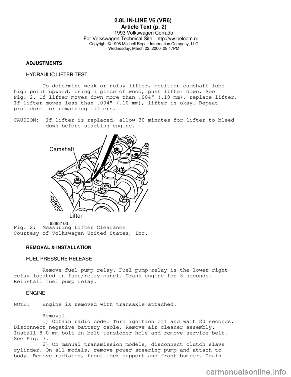
To determine weak or noisy lifter, position camshaft lobe
high point upward. Using a piece of wood, push lifter down. See
Fig. 2. If lifter moves down more than .004" (.10 mm), replace lifter.
If lifter moves less than .004" (.10 mm), lifter is okay. Repeat
procedure for remaining lifters.
CAUTION: If lifter is replaced, allow 30 minutes for lifter to bleed
down before starting engine.Fig. 2: Measuring Lifter Clearance
Courtesy of Volkswagen United States, Inc.
REMOVAL & INSTALLATION
FUEL PRESSURE RELEASE
Remove fuel pump relay. Fuel pump relay is the lower right
relay located in fuse/relay panel. Crank engine for 5 seconds.
Reinstall fuel pump relay.
ENGINE
NOTE: Engine is removed with transaxle attached.
Removal
1) Obtain radio code. Turn ignition off and wait 20 seconds.
Disconnect negative battery cable. Remove air cleaner assembly.
Install 8.0 mm bolt in belt tensioner hole and remove service belt.
See Fig. 3.
2) On manual transmission models, disconnect clutch slave
cylinder. On all models, remove power steering pump and attach to
body. Remove radiator, front lock support and front bumper. Drain
Page 301 of 920
2.8L IN-LINE V6 (VR6)
Article Text (p. 10)
1993 Volkswagen Corrado
For Volkswagen Technical Site: http://vw.belcom.ru
Copyright © 1998 Mitchell Repair Information Company, LLC
Wednesday, March 22, 2000 08:47PM
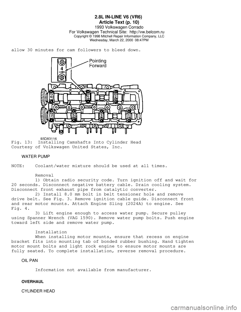
allow 30 minutes for cam followers to bleed down.Fig. 13: Installing Camshafts Into Cylinder Head
Courtesy of Volkswagen United States, Inc.
WATER PUMP
NOTE: Coolant/water mixture should be used at all times.
Removal
1) Obtain radio security code. Turn ignition off and wait for
20 seconds. Disconnect negative battery cable. Drain cooling system.
Disconnect front exhaust pipe from catalytic converter.
2) Install 8.0 mm bolt in belt tensioner hole and remove
drive belt. See Fig. 3. Remove ignition cable guide. Disconnect front
and rear motor mounts. Attach Engine Sling (2024A) to engine. See
Fig. 4.
3) Lift engine enough to access water pump. Secure pulley
using Spanner Wrench (VAG 1590). Remove water pump bolts. Push engine
toward left side and remove water pump.
Installation
When installing motor mounts, ensure that recess on engine
bracket fits into mounting tab of bonded rubber bushing. Hand tighten
motor mount bolts and light rock engine to ensure motor mounts are
fully seated. To complete installation, reverse removal procedure.
OIL PAN
Information not available from manufacturer.
OVERHAUL
CYLINDER HEAD
Page 375 of 920
A/C SYSTEM GENERAL SERVICING
Article Text (p. 7)
1993 Volkswagen Corrado
For Volkswagen Technical Site: http://vw.belcom.ru
Copyright © 1998 Mitchell Repair Information Company, LLC
Wednesday, March 22, 2000 08:48PM
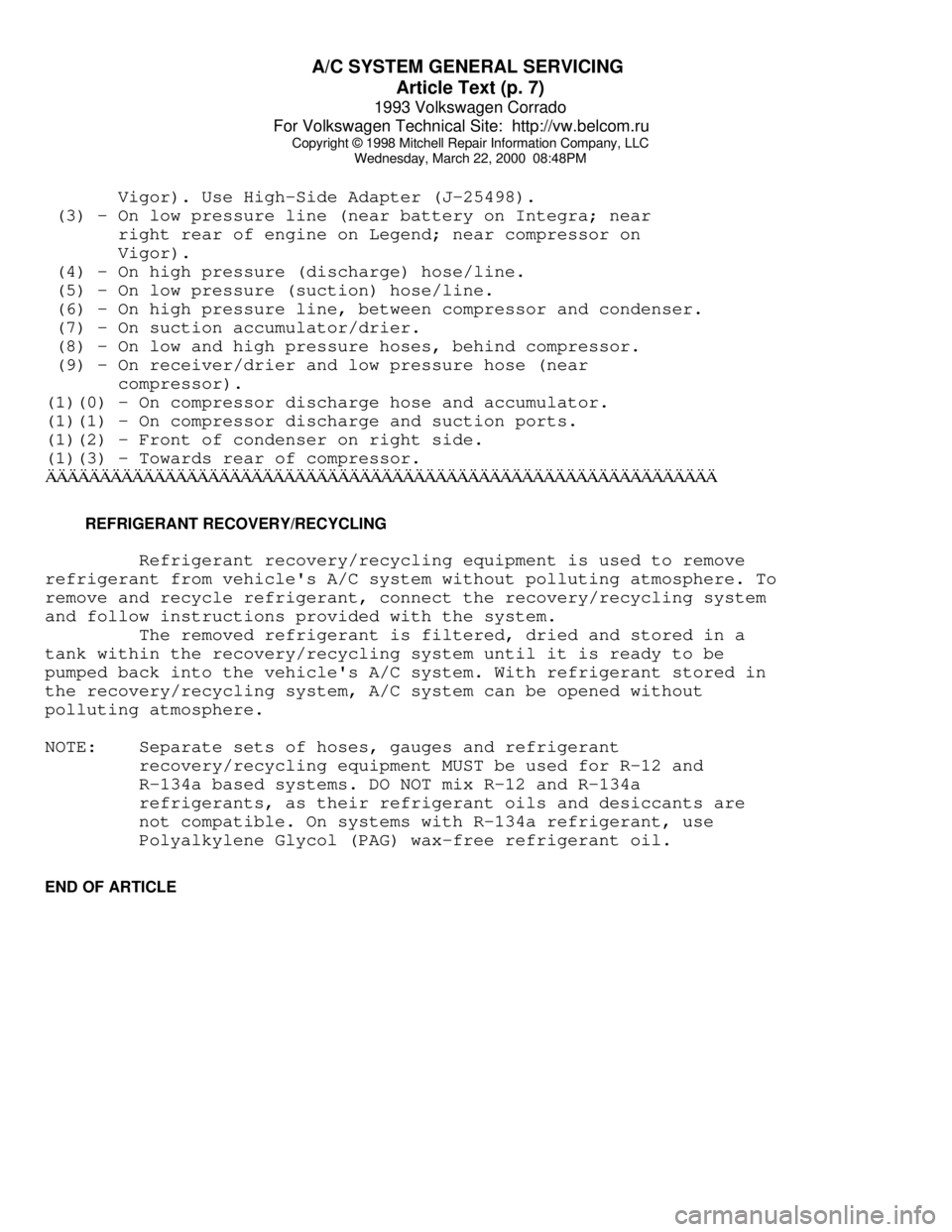
Vigor). Use High-Side Adapter (J-25498).
(3) - On low pressure line (near battery on Integra; near
right rear of engine on Legend; near compressor on
Vigor).
(4) - On high pressure (discharge) hose/line.
(5) - On low pressure (suction) hose/line.
(6) - On high pressure line, between compressor and condenser.
(7) - On suction accumulator/drier.
(8) - On low and high pressure hoses, behind compressor.
(9) - On receiver/drier and low pressure hose (near
compressor).
(1)(0) - On compressor discharge hose and accumulator.
(1)(1) - On compressor discharge and suction ports.
(1)(2) - Front of condenser on right side.
(1)(3) - Towards rear of compressor.ÄÄÄÄÄÄÄÄÄÄÄÄÄÄÄÄÄÄÄÄÄÄÄÄÄÄÄÄÄÄÄÄÄÄÄÄÄÄÄÄÄÄÄÄÄÄÄÄÄÄÄÄÄÄÄÄÄÄÄÄÄÄ REFRIGERANT RECOVERY/RECYCLING
Refrigerant recovery/recycling equipment is used to remove
refrigerant from vehicle's A/C system without polluting atmosphere. To
remove and recycle refrigerant, connect the recovery/recycling system
and follow instructions provided with the system.
The removed refrigerant is filtered, dried and stored in a
tank within the recovery/recycling system until it is ready to be
pumped back into the vehicle's A/C system. With refrigerant stored in
the recovery/recycling system, A/C system can be opened without
polluting atmosphere.
NOTE: Separate sets of hoses, gauges and refrigerant
recovery/recycling equipment MUST be used for R-12 and
R-134a based systems. DO NOT mix R-12 and R-134a
refrigerants, as their refrigerant oils and desiccants are
not compatible. On systems with R-134a refrigerant, use
Polyalkylene Glycol (PAG) wax-free refrigerant oil.
END OF ARTICLE
Page 377 of 920
A/C-HEATER SYSTEM - MANUAL
Article Text (p. 2)
1993 Volkswagen Corrado
For Volkswagen Technical Site: http://vw.belcom.ru
Copyright © 1998 Mitchell Repair Information Company, LLC
Wednesday, March 22, 2000 08:49PM
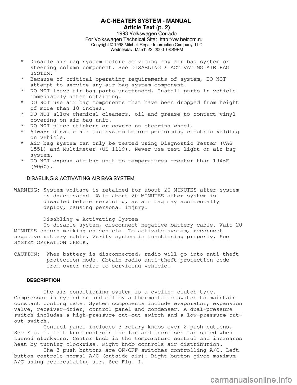
* Disable air bag system before servicing any air bag system or
steering column component. See DISABLING & ACTIVATING AIR BAG
SYSTEM.
* Because of critical operating requirements of system, DO NOT
attempt to service any air bag system component.
* DO NOT leave air bag parts unattended. Install parts in vehicle
immediately after obtaining.
* DO NOT use air bag components that have been dropped from height
of more than 18 inches.
* DO NOT allow chemical cleaners, oil and grease to contact vinyl
covering on air bag unit.
* DO NOT place stickers or covers on steering wheel.
* Always disable air bag system before performing electric welding
on vehicle.
* Air bag system can only be tested using Diagnostic Tester (VAG
1551) and Multimeter (US-1119). Never use test light on air bag
system.
* DO NOT expose air bag unit to temperatures greater than 194øF
(90
øC).
DISABLING & ACTIVATING AIR BAG SYSTEM
WARNING: System voltage is retained for about 20 MINUTES after system
is deactivated. Wait about 20 MINUTES after system is
disabled before servicing, as air bag may accidentally
deploy, causing personal injury.
Disabling & Activating System
To disable system, disconnect negative battery cable. Wait 20
MINUTES before working on vehicle. To activate system, reconnect
negative battery cable. Verify system is functioning properly. See
SYSTEM OPERATION CHECK.
CAUTION: When battery is disconnected, radio will go into anti-theft
protection mode. Obtain radio anti-theft protection code
from owner prior to servicing vehicle.
DESCRIPTION
The air conditioning system is a cycling clutch type.
Compressor is cycled on and off by a thermostatic switch to maintain
constant cooling rate. System components include evaporator, expansion
valve, receiver-drier, control panel and condenser. A dual-pressure
switch includes a high-pressure cut-out switch and a low-pressure cut-
out switch.
Control panel includes 3 rotary knobs over 2 push buttons.
See Fig. 1. Left knob controls the fan and increases fan speed when
turned clockwise. Center knob is the temperature control and increases
heat by turning clockwise. Right knob controls air distribution.
The 2 push buttons are ON/OFF switches controlling A/C. Left
button controls normal A/C (outside air). Right button gives maximum
A/C using recirculating air. See Fig. 1.