torque VOLKSWAGEN CORRADO 1993 Owner's Manual
[x] Cancel search | Manufacturer: VOLKSWAGEN, Model Year: 1993, Model line: CORRADO, Model: VOLKSWAGEN CORRADO 1993Pages: 920, PDF Size: 6.92 MB
Page 443 of 920
C - SPECIFICATIONS
Article Text (p. 3)
1993 Volkswagen Corrado
For Volkswagen Technical Site: http://vw.belcom.ru
Copyright © 1998 Mitchell Repair Information Company, LLC
Wednesday, March 22, 2000 08:58PM
stroke (waste spark). Ignition coil specifications
are not available from manufacturer.ÄÄÄÄÄÄÄÄÄÄÄÄÄÄÄÄÄÄÄÄÄÄÄÄÄÄÄÄÄÄÄÄÄÄÄÄÄÄÄÄÄÄÄÄÄÄÄÄÄÄÄÄÄÄÄ HIGH TENSION WIRE RESISTANCE
HIGH TENSION WIRE RESISTANCE
ÄÄÄÄÄÄÄÄÄÄÄÄÄÄÄÄÄÄÄÄÄÄÄÄÄÄÄÄÄÄÄÄÄÄÄÄÄÄÄÄÄÄÄÄÄÄÄÄÄÄÄÄÄÄÄApplication Ohms
Corrado SLC ..................................... (1)
(1) - Information is not available from manufacturer.
ÄÄÄÄÄÄÄÄÄÄÄÄÄÄÄÄÄÄÄÄÄÄÄÄÄÄÄÄÄÄÄÄÄÄÄÄÄÄÄÄÄÄÄÄÄÄÄÄÄÄÄÄÄÄÄ SPARK PLUGS
SPARK PLUG TYPE
ÄÄÄÄÄÄÄÄÄÄÄÄÄÄÄÄÄÄÄÄÄÄÄÄÄÄÄÄÄÄÄÄÄÄÄÄÄÄÄÄÄÄÄÄÄÄÄÄÄÄÄÄÄÄÄApplication Bosch
Corrado SLC ................................... C9MCC
ÄÄÄÄÄÄÄÄÄÄÄÄÄÄÄÄÄÄÄÄÄÄÄÄÄÄÄÄÄÄÄÄÄÄÄÄÄÄÄÄÄÄÄÄÄÄÄÄÄÄÄÄÄÄÄSPARK PLUG SPECIFICATIONS
ÄÄÄÄÄÄÄÄÄÄÄÄÄÄÄÄÄÄÄÄÄÄÄÄÄÄÄÄÄÄÄÄÄÄÄÄÄÄÄÄÄÄÄÄÄÄÄÄÄÄÄÄÄÄÄ Gap Torque
Application In. (mm) Ft. Lbs. (N.m)
Corrado SLC ..... .028-.031 (.70-.80) ..... 18 (25)
ÄÄÄÄÄÄÄÄÄÄÄÄÄÄÄÄÄÄÄÄÄÄÄÄÄÄÄÄÄÄÄÄÄÄÄÄÄÄÄÄÄÄÄÄÄÄÄÄÄÄÄÄÄÄÄ FIRING ORDER & TIMING MARKS
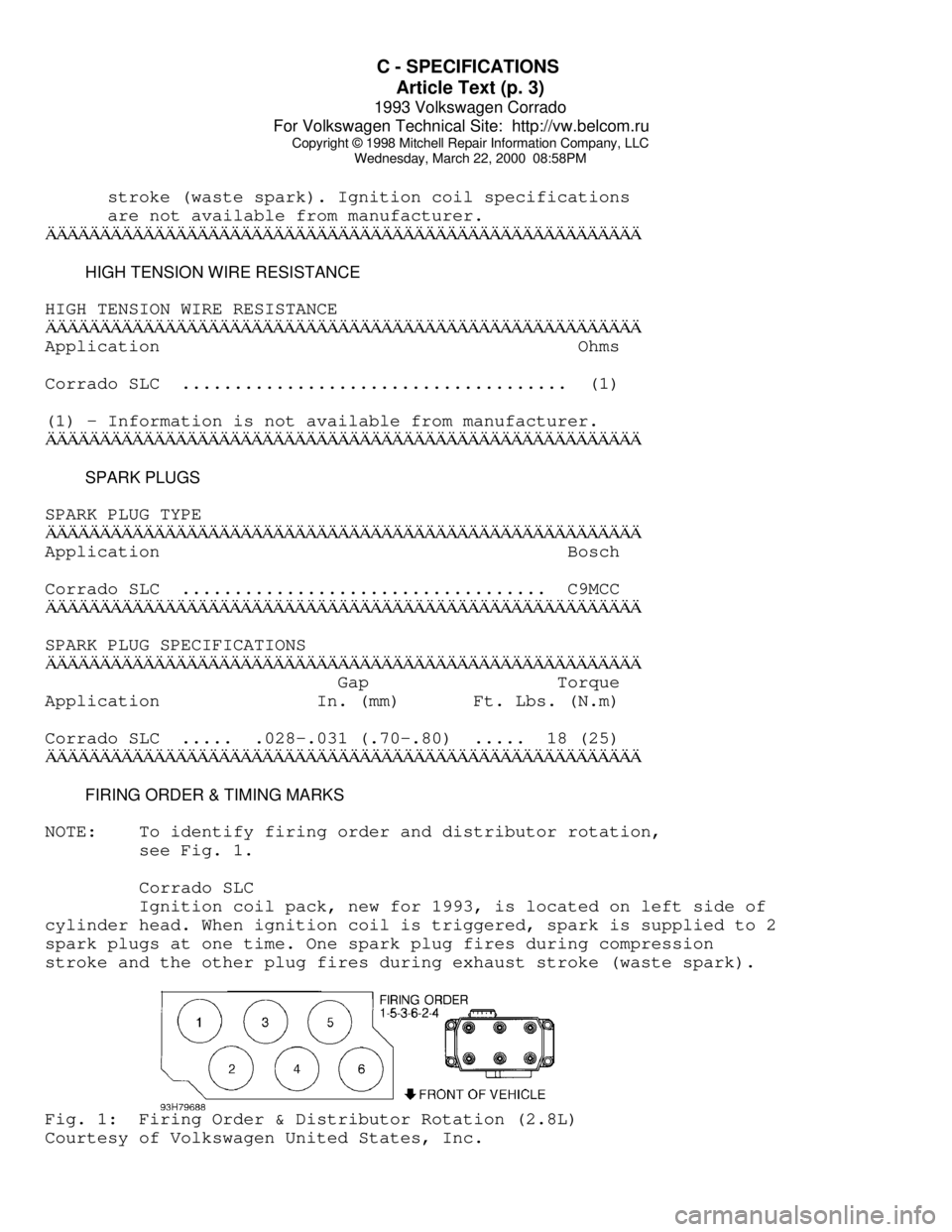
NOTE: To identify firing order and distributor rotation,
see Fig. 1.
Corrado SLC
Ignition coil pack, new for 1993, is located on left side of
cylinder head. When ignition coil is triggered, spark is supplied to 2
spark plugs at one time. One spark plug fires during compression
stroke and the other plug fires during exhaust stroke (waste spark).Fig. 1: Firing Order & Distributor Rotation (2.8L)
Courtesy of Volkswagen United States, Inc.
Page 449 of 920
CLUTCH
Article Text (p. 4)
1993 Volkswagen Corrado
For Volkswagen Technical Site: http://vw.belcom.ru
Copyright © 1998 Mitchell Repair Information Company, LLC
Wednesday, March 22, 2000 08:58PM
* Worn To Surface Of Rivet Heads
* Rivets Are Loose, Missing Or Damaged
* Friction Material Is Oil Or Grease Soaked
* Friction Material Is Loose, Cracked Or Grooved
* Hub Is Rusted Or Damaged
* Springs Are Rusted Solid, Broken, Cracked Or Loose
* Torsion Damper Spring Guide Is Broken
* Torsion Damper Cover Damaged
* Torsion Damper Grooved Or Not Functioning
NOTE: Pressure plate has a protective grease coating. Remove
contact surface grease only. Service life will be shortened
if remaining portions of pressure plate protective grease
are removed.
Installation
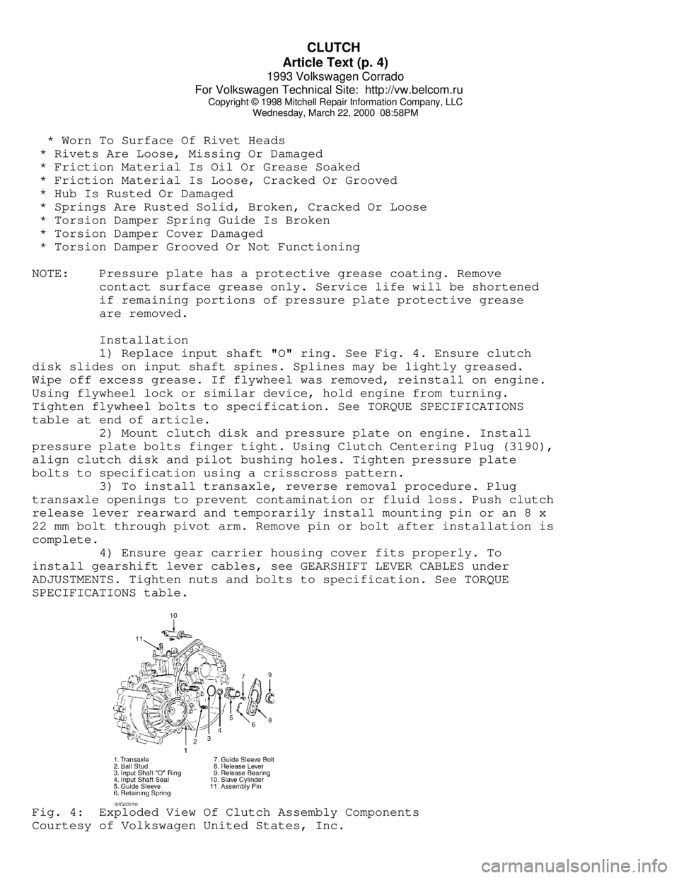
1) Replace input shaft "O" ring. See Fig. 4. Ensure clutch
disk slides on input shaft spines. Splines may be lightly greased.
Wipe off excess grease. If flywheel was removed, reinstall on engine.
Using flywheel lock or similar device, hold engine from turning.
Tighten flywheel bolts to specification. See TORQUE SPECIFICATIONS
table at end of article.
2) Mount clutch disk and pressure plate on engine. Install
pressure plate bolts finger tight. Using Clutch Centering Plug (3190),
align clutch disk and pilot bushing holes. Tighten pressure plate
bolts to specification using a crisscross pattern.
3) To install transaxle, reverse removal procedure. Plug
transaxle openings to prevent contamination or fluid loss. Push clutch
release lever rearward and temporarily install mounting pin or an 8 x
22 mm bolt through pivot arm. Remove pin or bolt after installation is
complete.
4) Ensure gear carrier housing cover fits properly. To
install gearshift lever cables, see GEARSHIFT LEVER CABLES under
ADJUSTMENTS. Tighten nuts and bolts to specification. See TORQUE
SPECIFICATIONS table.Fig. 4: Exploded View Of Clutch Assembly Components
Courtesy of Volkswagen United States, Inc.
Page 450 of 920
CLUTCH
Article Text (p. 5)
1993 Volkswagen Corrado
For Volkswagen Technical Site: http://vw.belcom.ru
Copyright © 1998 Mitchell Repair Information Company, LLC
Wednesday, March 22, 2000 08:58PM
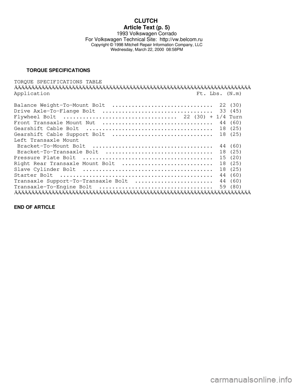
TORQUE SPECIFICATIONS
TORQUE SPECIFICATIONS TABLEÄÄÄÄÄÄÄÄÄÄÄÄÄÄÄÄÄÄÄÄÄÄÄÄÄÄÄÄÄÄÄÄÄÄÄÄÄÄÄÄÄÄÄÄÄÄÄÄÄÄÄÄÄÄÄÄÄÄÄÄÄÄÄÄÄÄÄÄÄÄApplication Ft. Lbs. (N.m)
Balance Weight-To-Mount Bolt ............................... 22 (30)
Drive Axle-To-Flange Bolt .................................. 33 (45)
Flywheel Bolt ................................... 22 (30) + 1/4 Turn
Front Transaxle Mount Nut .................................. 44 (60)
Gearshift Cable Bolt ....................................... 18 (25)
Gearshift Cable Support Bolt ............................... 18 (25)
Left Transaxle Mount
Bracket-To-Mount Bolt ..................................... 44 (60)
Bracket-To-Transaxle Bolt ................................. 18 (25)
Pressure Plate Bolt ........................................ 15 (20)
Right Rear Transaxle Mount Bolt ............................ 18 (25)
Slave Cylinder Bolt ........................................ 18 (25)
Starter Bolt ............................................... 44 (60)
Transaxle Support-To-Transaxle Bolt ........................ 44 (60)
Transaxle-To-Engine Bolt ................................... 59 (80)
ÄÄÄÄÄÄÄÄÄÄÄÄÄÄÄÄÄÄÄÄÄÄÄÄÄÄÄÄÄÄÄÄÄÄÄÄÄÄÄÄÄÄÄÄÄÄÄÄÄÄÄÄÄÄÄÄÄÄÄÄÄÄÄÄÄÄÄÄÄÄEND OF ARTICLE
Page 534 of 920
ENGINE OVERHAUL PROCEDURES - GENERAL INFORMATION
Article Text (p. 5)
1993 Volkswagen Corrado
For Volkswagen Technical Site: http://vw.belcom.ru
Copyright © 1998 Mitchell Repair Information Company, LLC
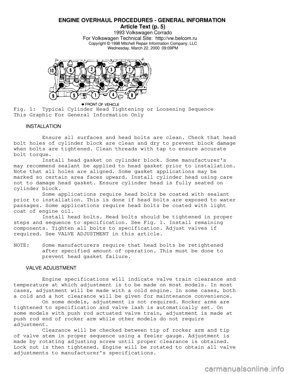
Wednesday, March 22, 2000 09:09PMFig. 1: Typical Cylinder Head Tightening or Loosening Sequence
This Graphic For General Information Only
INSTALLATION
Ensure all surfaces and head bolts are clean. Check that head
bolt holes of cylinder block are clean and dry to prevent block damage
when bolts are tightened. Clean threads with tap to ensure accurate
bolt torque.
Install head gasket on cylinder block. Some manufacturer's
may recommend sealant be applied to head gasket prior to installation.
Note that all holes are aligned. Some gasket applications may be
marked so certain area faces upward. Install cylinder head using care
not to damage head gasket. Ensure cylinder head is fully seated on
cylinder block.
Some applications require head bolts be coated with sealant
prior to installation. This is done if head bolts are exposed to water
passages. Some applications require head bolts be coated with light
coat of engine oil.
Install head bolts. Head bolts should be tightened in proper
steps and sequence to specification. See Fig. 1. Install remaining
components. Tighten all bolts to specification. Adjust valves if
required. See VALVE ADJUSTMENT in this article.
NOTE: Some manufacturers require that head bolts be retightened
after specified amount of operation. This must be done to
prevent head gasket failure.
VALVE ADJUSTMENT
Engine specifications will indicate valve train clearance and
temperature at which adjustment is to be made on most models. In most
cases, adjustment will be made with a cold engine. In some cases, both
a cold and a hot clearance will be given for maintenance convenience.
On some models, adjustment is not required. Rocker arms are
tightened to specification and valve lash is automatically set. On
some models with push rod actuated valve train, adjustment is made at
push rod end of rocker arm while other models do not require
adjustment.
Clearance will be checked between tip of rocker arm and tip
of valve stem in proper sequence using a feeler gauge. Adjustment is
made by rotating adjusting screw until proper clearance is obtained.
Lock nut is then tightened. Engine will be rotated to obtain all valve
adjustments to manufacturer's specifications.
Page 554 of 920

ENGINE OVERHAUL PROCEDURES - GENERAL INFORMATION
Article Text (p. 25)
1993 Volkswagen Corrado
For Volkswagen Technical Site: http://vw.belcom.ru
Copyright © 1998 Mitchell Repair Information Company, LLC
Wednesday, March 22, 2000 09:10PMFig. 22: Checking Crankshaft End Play - Typical
This Graphic For General Information Only
Crankshaft end play must be within specification. If end
play is not within specification, check for faulty thrust bearing
installation or worn crankshaft. Some applications offer oversized
thrust bearings.
CYLINDER BLOCK
* PLEASE READ THIS FIRST *
NOTE: Always refer to appropriate engine overhaul article in the
ENGINES section for complete overhaul procedures and
specifications for the vehicle being repaired.
BLOCK CLEANING
Only cast cylinder blocks should be hot tank cleaned.
Aluminum cylinder blocks should be cleaned using cold tank method.
Cylinder block is cleaned in order to remove carbon deposits, gasket
residue and water jacket scale. Remove oil galley plugs, freeze plugs
and cam bearings prior to block cleaning.
BLOCK INSPECTION
Visually inspect the block. Check suspected areas for cracks
using the Dye Penetrant inspection method. Block may be checked for
cracks using the Magnaflux method.
Cracks are most commonly found at the bottom of the
cylinders, the main bearing saddles, near expansion plugs and between
the cylinders and water jackets. Inspect lifter bores for damage.
Inspect all head bolt holes for damaged threads. Threads should be
cleaned using tap to ensure proper head bolt torque. Consult machine
shop concerning possible welding and machining (if required).
Page 611 of 920
HOW TO USE SYSTEM WIRING DIAGRAMS
Article Text (p. 8)
1993 Volkswagen Corrado
For Volkswagen Technical Site: http://vw.belcom.ru
Copyright © 1998 Mitchell Repair Information Company, LLC
Wednesday, March 22, 2000 09:11PM
Power Top Relay(s) ........................... Power Convertible Top
Powertrain Control Module ....................... Engine Performance
Analog Instrument Panels
Cruise Control Systems
Data Link Connectors
Generators & Regulators
Starters
Power Window Motors .................................. Power Windows
Power Window Relay(s) ................................ Power Windows
Radiator Fan Motor(s) ........................ Electric Cooling Fans
Radiator Fan Relay(s) ........................... Engine Performance
Electric Cooling Fans
Rainsense Module .............................. Wiper/Washer Systems
Raise Relay .................................. Power Convertible Top
Remote Anti-Theft Personality (RAP) Module ....... Anti-Theft System
Starters
Warning Systems
Seat Belt Pretensioners ................... Air Bag Restraint System
Seat Belt Retractor Solenoid .................... Passive Restraints
Seat Belt Switch .......................... Air Bag Restraint System
Passive Restraints
Shift Interlock Solenoid ................... Shift Interlock Systems
Shift Lock Actuator ........................ Shift Interlock Systems
Side Marker Lights ................................. Exterior Lights
SIR Coil Assembly (Clockspring) ........... Air Bag Restraint System
Slip Ring (Clockspring) ................... Air Bag Restraint System
Steering Column Switches
SRS Control Module ........................ Air Bag Restraint System
Starter Motor ............................................. Starters
Starter Interrupt Relay ................................... Starters
Starter Solenoid .......................................... Starters
Starter Relay ............................................. Starters
Steering Wheel Position Sensor .................... Anti-Lock Brakes
Stoplights ......................................... Exterior Lights
Stoplight Switch ................................ Engine Performance
Cruise Control Systems
Anti-Lock Brakes
Sun Roof ECU ........................................ Power Sun Roof
Sun Roof Motor ...................................... Power Sun Roof
Sun Roof Position Sensor ............................ Power Sun Roof
Taillights ......................................... Exterior Lights
Throttle Position (TP) Sensor ................... Engine Performance
Torque Converter Clutch Solenoid/Switch ......... Engine Performance
Traction Control Switch ........................... Anti-Lock Brakes
Trailer Tow Connector .............................. Exterior Lights
Trailer Tow Relay .................................. Exterior Lights
Transmission/Transaxle .......................... Engine Performance
Transmission Control Module (TCM) ............... Engine Performance
Starters
Transmission Range Sensor ................................. Starters
Back-Up Lights
Engine Performance
Page 671 of 920
METRIC CONVERSIONS
Article Text
1993 Volkswagen Corrado
For Volkswagen Technical Site: http://vw.belcom.ru
Copyright © 1998 Mitchell Repair Information Company, LLC
Wednesday, March 22, 2000 09:20PM
ARTICLE BEGINNING
GENERAL INFORMATION
METRIC CONVERSIONS
METRIC CONVERSIONS
Metric conversions are making life more difficult for the
mechanic. In addition to doubling the number of tools required,
metric-dimensioned nuts and bolts are used alongside English
components in many new vehicles. The mechanic has to decide which tool
to use, slowing down the job. The tool problem can be solved by trial
and error, but some metric conversions aren't so simple. Converting
temperature, lengths or volumes requires a calculator and conversion
charts, or else a very nimble mind. Conversion charts are only part of
the answer though, because they don't help you "think" metric, or
"visualize" what you are converting. The following examples are
intended to help you "see" metric sizes:
LENGTH
Meters are the standard unit of length in the metric system.
The smaller units are 10ths (decimeter), 100ths (centimeter), and
1000ths (millimeter) of a meter. These common examples might help you
to visualize the metric units:
* A meter is slightly longer than a yard (about 40 inches).
* An aspirin tablet is about one centimeter across (.4 inches).
* A millimeter is about the thickness of a dime.
VOLUME
Cubic meters and centimeters are used to measure volume, just
as we normally think of cubic feet and inches. Liquid volume
measurements include the liter and milliliter, like the English quarts
or ounces.
* One teaspoon is about 4 cubic centimeters.
* A liter is about one quart.
* A liter is about 61 cubic inches.
WEIGHT
The metric weight system is based on the gram, with the most
common unit being the kilogram (1000 grams). Our comparable units are
ounces and pounds:
* A kilogram is about 2.2 pounds.
* An ounce is about 28 grams.
TORQUE
Page 672 of 920
METRIC CONVERSIONS
Article Text (p. 2)
1993 Volkswagen Corrado
For Volkswagen Technical Site: http://vw.belcom.ru
Copyright © 1998 Mitchell Repair Information Company, LLC
Wednesday, March 22, 2000 09:20PM
Torque is somewhat complicated. The term describes the amount
of effort exerted to turn something. A chosen unit of weight or force
is applied to a lever of standard length. The resulting leverage is
called torque. In our standard system, we use the weight of one pound
applied to a lever a foot long, resulting in the unit called a foot-
pound. A smaller unit is the inch-pound (the lever is one inch long).
Metric units include the meter kilogram (lever one meter long
with a kilogram of weight applied) and the Newton-meter (lever one
meter long with force of one Newton applied). Some conversions are:
* A meter kilogram is about 7.2 foot pounds.
* A foot pound is about 1.4 Newton-meters.
* A centimeter kilogram (cmkg) is equal to .9 inch pounds.
PRESSURE
Pressure is another complicated measurement. Pressure is
described as a force or weight applied to a given area. Our common
unit is pounds per square inch. Metric units can be expressed in
several ways. One is the kilogram per square centimeter (kg/cmý).
Another unit of pressure is the Pascal (force of one Newton on an area
of one square meter), which equals about 4 ounces on a square yard.
Since this is a very small amount of pressure, we usually see the
kiloPascal, or kPa (1000 Pascals). Another common automotive term for
pressure is the bar (used by German manufacturers), which equals 10
Pascals. Thoroughly confused? Try the examples below:
* Atmospheric pressure at sea level is about 14.7 psi.
* Atmospheric pressure at sea level is about 1 bar.
* Atmospheric pressure at sea level is about 1 kg/cm
ý.
* One pound per square inch is about 7 kPa.
CONVERSION FACTORS
CONVERSION FACTORS
ÚÄÄÄÄÄÄÄÄÄÄÄÄÄÄÄÄÄÄÄÄÄÄÄÄÄÄÄÂÄÄÄÄÄÄÄÄÄÄÄÄÄÄÄÄÄÄÄÄÄÄÄÂÄÄÄÄÄÄÄÄÄÄÄÄÄÄ¿
³TO CONVERT
³TO ³ MULTIPLY BY ³
ÃÄÄÄÄÄÄÄÄÄÄÄÄÄÄÄÄÄÄÄÄÄÄÄÄÄÄÄÅÄÄÄÄÄÄÄÄÄÄÄÄÄÄÄÄÄÄÄÄÄÄÄÅÄÄÄÄÄÄÄÄÄÄÄÄÄÄ´
³LENGTH
³ ³ ³
³Millimeters (mm)
³Inches ³ .03937 ³
³Inches
³Millimeters ³ 25.4 ³
³Meters (M)
³Feet ³ 3.28084 ³
³Feet
³Meters ³ .3048 ³
³Kilometers(Km)
³Miles ³ .62137 ³
ÃÄÄÄÄÄÄÄÄÄÄÄÄÄÄÄÄÄÄÄÄÄÄÄÄÄÄÄÅÄÄÄÄÄÄÄÄÄÄÄÄÄÄÄÄÄÄÄÄÄÄÄÅÄÄÄÄÄÄÄÄÄÄÄÄÄÄ´
³AREA
³ ³ ³
³Square Centimeters (cm
ý) ³Square Inches ³ .155 ³
³Square Inches
³Square Centimeters ³ 6.45159 ³
ÃÄÄÄÄÄÄÄÄÄÄÄÄÄÄÄÄÄÄÄÄÄÄÄÄÄÄÄÅÄÄÄÄÄÄÄÄÄÄÄÄÄÄÄÄÄÄÄÄÄÄÄÅÄÄÄÄÄÄÄÄÄÄÄÄÄÄ´
³VOLUME
³ ³ ³
³Cubic Centimeters
³Cubic Inches ³ .06103 ³
Page 678 of 920
N - REMOVE/INSTALL/OVERHAUL
Article Text
1993 Volkswagen Corrado
For Volkswagen Technical Site: http://vw.belcom.ru
Copyright © 1998 Mitchell Repair Information Company, LLC
Wednesday, March 22, 2000 09:21PM
ARTICLE BEGINNING
1993 ENGINE PERFORMANCE
Removal, Overhaul & Installation
Corrado SLC
CAUTION: When battery is disconnected, vehicle computer and memory
systems may lose memory data. Driveability problems may
exist until computer systems have completed a relearn
cycle. See the COMPUTER RELEARN PROCEDURES article in
GENERAL INFORMATION before disconnecting battery.
INTRODUCTION
Removal, overhaul and installation procedures are covered in
this article. If component removal and installation is primarily an
unbolt and bolt-on procedure, only a torque specification may be
furnished.
CAUTION: When disconnecting battery, obtain and record radio
anti-theft code. If wrong code is entered into radio after
power is restored, radio will become inoperable.
IGNITION SYSTEM
NOTE: Corrado SLC ignition system removal and installation
information not available from manufacturer. These vehicles
are equipped with a distributorless ignition system.
DISTRIBUTOR
FUEL SYSTEM
FUEL SYSTEM PRESSURE RELEASE
To relieve fuel system pressure, remove fuel pump fuse (No.
5, 13 or 18) or fuel pump relay to deactivate fuel pump. Place a clean
shop rag around fuel line fitting and slowly loosen fitting.
WARNING: Fuel system pressure release procedure is not available
from manufacturer. Fuel will discharge when disconnecting
fuel system components. Disconnect ignition coil output
stage wiring harness to deactivate ignition. DO NOT smoke
or work near heaters or other fire hazards. Keep a fire
extinguisher handy.
FUEL PUMP
Removal & Installation (Corrado SLC)
1) Obtain and record radio anti-theft code. Disconnect
Page 679 of 920
N - REMOVE/INSTALL/OVERHAUL
Article Text (p. 2)
1993 Volkswagen Corrado
For Volkswagen Technical Site: http://vw.belcom.ru
Copyright © 1998 Mitchell Repair Information Company, LLC
Wednesday, March 22, 2000 09:21PM
negative battery cable. Remove luggage compartment floor covering and
fuel pump access cover. Disconnect wiring harness and fuel lines from
fuel pump.
2) Using Wrench (3217), loosen fuel pump screw cap. Remove
flange and sealing ring from fuel tank opening. Loosen fuel pump by
twisting it to left. Remove fuel pump from fuel tank.
3) When installing fuel pump, ensure that fuel gauge sending
unit is not bent. Sending unit must be installed with a frontal angle
of 5 degrees. Align mark on flange with fuel tank. To complete
installation, reverse removal procedure.
FUEL PUMP CHECK VALVE
FUEL RAIL & INJECTORS
Removal & Installation (Corrado SLC)
1) Remove ignition wires. Remove hose from mass airflow
sensor. Disconnect hose to fuel evaporative (frequency) solenoid valve
at throttle body.
2) Disconnect throttle position sensor and idle air control
valve. Disconnect accelerator cable from throttle body. Disconnect and
plug coolant hoses at throttle body.
3) Disconnect hose from air intake heated tube. Detach fuel
lines at cylinder head cover and remove from fuel rail. Disconnect
vacuum hose from fuel pressure regulator. Remove upper intake
manifold.
4) With upper intake manifold removed, disconnect wiring
harness from fuel injector(s). Pry off retaining clip(s) from
injector(s). To install injectors, lubricate "O" rings with fuel. To
complete installation, reverse removal procedure.
TORQUE SPECIFICATIONS
TORQUE SPECIFICATIONS (CORRADO SLC)ÄÄÄÄÄÄÄÄÄÄÄÄÄÄÄÄÄÄÄÄÄÄÄÄÄÄÄÄÄÄÄÄÄÄÄÄÄÄÄÄÄÄÄÄÄÄÄÄÄÄÄÄÄÄÄApplication Ft. Lbs. (N.m)
EGR Temperature Sensor ...................... 15 (20)
Knock Sensors ............................... 18 (25)
Oxygen Sensor ............................... 37 (50)
Throttle Body Bolts ......................... 18 (25)
Upper Intake Manifold Bolts ................. 18 (25)
INCH Lbs. (N.m)
FUEL RAIL BOLTS ............................. 84 (10)
Intake Air Temperature Sensor ............... 84 (10)
ÄÄÄÄÄÄÄÄÄÄÄÄÄÄÄÄÄÄÄÄÄÄÄÄÄÄÄÄÄÄÄÄÄÄÄÄÄÄÄÄÄÄÄÄÄÄÄÄÄÄÄÄÄÄÄEND OF ARTICLE