relay VOLKSWAGEN CORRADO 1993 Manual PDF
[x] Cancel search | Manufacturer: VOLKSWAGEN, Model Year: 1993, Model line: CORRADO, Model: VOLKSWAGEN CORRADO 1993Pages: 920, PDF Size: 6.92 MB
Page 840 of 920
TROUBLE SHOOTING - BASIC PROCEDURES
Article Text (p. 49)
1993 Volkswagen Corrado
For Volkswagen Technical Site: http://vw.belcom.ru
Copyright © 1998 Mitchell Repair Information Company, LLC
Wednesday, March 22, 2000 09:26PM
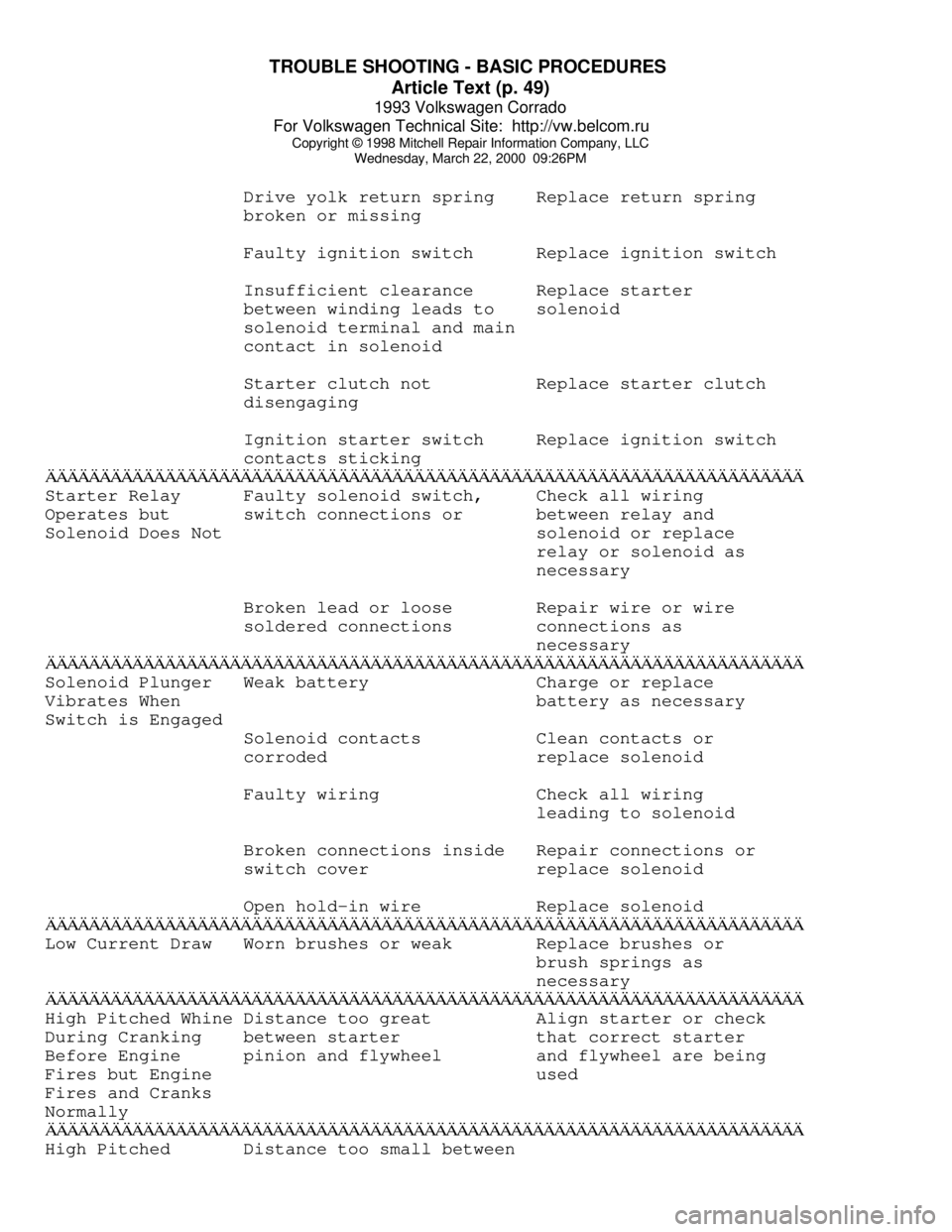
Drive yolk return spring Replace return spring
broken or missing
Faulty ignition switch Replace ignition switch
Insufficient clearance Replace starter
between winding leads to solenoid
solenoid terminal and main
contact in solenoid
Starter clutch not Replace starter clutch
disengaging
Ignition starter switch Replace ignition switch
contacts stickingÄÄÄÄÄÄÄÄÄÄÄÄÄÄÄÄÄÄÄÄÄÄÄÄÄÄÄÄÄÄÄÄÄÄÄÄÄÄÄÄÄÄÄÄÄÄÄÄÄÄÄÄÄÄÄÄÄÄÄÄÄÄÄÄÄÄÄÄÄÄStarter Relay Faulty solenoid switch, Check all wiring
Operates but switch connections or between relay and
Solenoid Does Not solenoid or replace
relay or solenoid as
necessary
Broken lead or loose Repair wire or wire
soldered connections connections as
necessary
ÄÄÄÄÄÄÄÄÄÄÄÄÄÄÄÄÄÄÄÄÄÄÄÄÄÄÄÄÄÄÄÄÄÄÄÄÄÄÄÄÄÄÄÄÄÄÄÄÄÄÄÄÄÄÄÄÄÄÄÄÄÄÄÄÄÄÄÄÄÄSolenoid Plunger Weak battery Charge or replace
Vibrates When battery as necessary
Switch is Engaged
Solenoid contacts Clean contacts or
corroded replace solenoid
Faulty wiring Check all wiring
leading to solenoid
Broken connections inside Repair connections or
switch cover replace solenoid
Open hold-in wire Replace solenoid
ÄÄÄÄÄÄÄÄÄÄÄÄÄÄÄÄÄÄÄÄÄÄÄÄÄÄÄÄÄÄÄÄÄÄÄÄÄÄÄÄÄÄÄÄÄÄÄÄÄÄÄÄÄÄÄÄÄÄÄÄÄÄÄÄÄÄÄÄÄÄLow Current Draw Worn brushes or weak Replace brushes or
brush springs as
necessary
ÄÄÄÄÄÄÄÄÄÄÄÄÄÄÄÄÄÄÄÄÄÄÄÄÄÄÄÄÄÄÄÄÄÄÄÄÄÄÄÄÄÄÄÄÄÄÄÄÄÄÄÄÄÄÄÄÄÄÄÄÄÄÄÄÄÄÄÄÄÄHigh Pitched Whine Distance too great Align starter or check
During Cranking between starter that correct starter
Before Engine pinion and flywheel and flywheel are being
Fires but Engine used
Fires and Cranks
Normally
ÄÄÄÄÄÄÄÄÄÄÄÄÄÄÄÄÄÄÄÄÄÄÄÄÄÄÄÄÄÄÄÄÄÄÄÄÄÄÄÄÄÄÄÄÄÄÄÄÄÄÄÄÄÄÄÄÄÄÄÄÄÄÄÄÄÄÄÄÄÄHigh Pitched Distance too small between
Page 902 of 920
WIRING DIAGRAM SYMBOLS
Article Text
1993 Volkswagen Corrado
For Volkswagen Technical Site: http://vw.belcom.ru
Copyright © 1998 Mitchell Repair Information Company, LLC
Wednesday, March 22, 2000 09:27PM
ARTICLE BEGINNING
WIRING DIAGRAMS
How To Use The Wiring Diagrams
INTRODUCTION
The wiring diagrams and technical service bulletins,
containing wiring diagram changes, are obtained from the domestic and
import manufacturers. These are checked for accuracy and are all
redrawn into a consistent format for easy use.
All diagrams are arranged with the front of the vehicle at
the left side of the first page and the rear of the vehicle at the
right side of the last page. Accessories are shown near the end of the
diagram.
Components are shown in their approximate location on the
vehicle. Due to the constantly increasing number of components on
vehicles today, it is impossible to show exact locations.
In the past, when cars were simpler, diagrams were simpler.
All components were connected by wires, and diagrams seldom exceeded 4
pages in length. Today some wiring diagrams require more than 16
pages. It would be impractical to expect a service technician to trace
a wire from page 1 across every page to page 16.
Removing some of the wiring maze reduces eyestrain and time
wasted searching across several pages. Today, the majority of diagrams
now follow a much improved format, which permits space for internal
switch details and connector shapes.
Any wires that don't connect directly to their components are
identified on the diagram to indicate where they go. There is a legend
on the first page of each diagram, detailing component location. It
refers you to sub-systems, using grid NUMBERS at the top and bottom of
the page and grid LETTERS on each side. This grid system works in a
manner similar to that of a road map.
HOW TO USE THE WIRING DIAGRAMS
1) On the first page of the diagram, you will find a listing
of major electrical components or systems. Locate the specific
component or system you wish to trace. A grid number and letter will
follow the component's name.
2) Use the grid NUMBERS (arranged horizontally across the top
and bottom of each page) to find the page of the wiring diagram that
contains the component you're seeking. When you reach this page, use
the grid LETTERS on the side of the page to determine the component's
vertical location.
3) Locate the circuit you need to service. The internals are
shown for switches and relays to assist you in understanding how the
circuit operates.
NOTE: In some of the newer wiring diagram articles in this
product, there is a Legend for the wiring diagrams that has
Page 904 of 920
WIRING DIAGRAM SYMBOLS
Article Text (p. 3)
1993 Volkswagen Corrado
For Volkswagen Technical Site: http://vw.belcom.ru
Copyright © 1998 Mitchell Repair Information Company, LLC
Wednesday, March 22, 2000 09:27PM
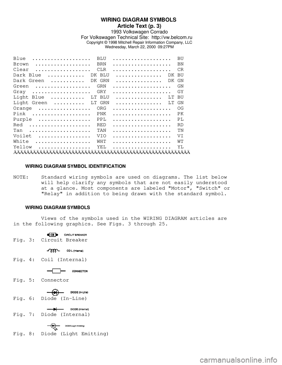
Blue ................... BLU ................... BU
Brown .................. BRN ................... BN
Clear .................. CLR ................... CR
Dark Blue ............ DK BLU ............... DK BU
Dark Green ........... DK GRN ............... DK GN
Green .................. GRN ................... GN
Gray ................... GRY ................... GY
Light Blue ........... LT BLU ............... LT BU
Light Green .......... LT GRN ............... LT GN
Orange ................. ORG ................... OG
Pink ................... PNK ................... PK
Purple ................. PPL ................... PL
Red .................... RED ................... RD
Tan .................... TAN ................... TN
Voilet ................. VIO ................... VI
White .................. WHT ................... WT
Yellow ................. YEL ................... YLÄÄÄÄÄÄÄÄÄÄÄÄÄÄÄÄÄÄÄÄÄÄÄÄÄÄÄÄÄÄÄÄÄÄÄÄÄÄÄÄÄÄÄÄÄÄÄÄÄÄÄÄÄÄÄ WIRING DIAGRAM SYMBOL IDENTIFICATION
NOTE: Standard wiring symbols are used on diagrams. The list below
will help clarify any symbols that are not easily understood
at a glance. Most components are labeled "Motor", "Switch" or
"Relay" in addition to being drawn with the standard symbol.
WIRING DIAGRAM SYMBOLS
Views of the symbols used in the WIRING DIAGRAM articles are
in the following graphics. See Figs. 3 through 25.Fig. 3: Circuit BreakerFig. 4: Coil (Internal)Fig. 5: ConnectorFig. 6: Diode (In-Line)Fig. 7: Diode (Internal)Fig. 8: Diode (Light Emitting)
Page 907 of 920
WIRING DIAGRAMS
Article Text
1993 Volkswagen Corrado
For Volkswagen Technical Site: http://vw.belcom.ru
Copyright © 1998 Mitchell Repair Information Company, LLC
Wednesday, March 22, 2000 09:28PM
ARTICLE BEGINNING
1993 WIRING DIAGRAMS
Volkswagen Wiring Diagrams
Volkswagen; Corrado
COMPONENT LOCATION MENU
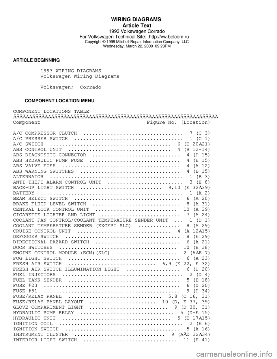
COMPONENT LOCATIONS TABLEÄÄÄÄÄÄÄÄÄÄÄÄÄÄÄÄÄÄÄÄÄÄÄÄÄÄÄÄÄÄÄÄÄÄÄÄÄÄÄÄÄÄÄÄÄÄÄÄÄÄÄÄÄÄÄÄÄÄÄÄÄÄÄÄÄComponent Figure No. (Location)
A/C COMPRESSOR CLUTCH ................................. 7 (C 3)
A/C PRESSER SWITCH .................................... 1 (C 1)
A/C SWITCH ........................................ 6 (E 20
Ä21)
ABS CONTROL UNIT .................................. 4 (B 12-14)
ABS DIAGNOSTIC CONNECTOR ............................. 4 (D 15)
ABS HYDRAULIC PUMP FUSE .............................. 4 (E 15)
ABS VALVE FUSE ....................................... 4 (A 12)
ABS WARNING SWITCHES ................................. 4 (B 15)
ALTERNATOR ............................................ 1 (B 3)
ANTI-THEFT ALARM CONTROL UNIT ......................... 3 (E 8)
BACK-UP LIGHT SWITCH ........................... 9,10 (E 32
Ä39)
BATTERY ............................................... 1 (A 2)
BEAM SELECT SWITCH ................................... 6 (A 20)
BRAKE FLUID LEVEL SWITCH ............................. 8 (A 31)
CENTRAL LOCK CONTROL UNIT ........................... 10 (A 39)
CIGARETTE LIGHTER AND LIGHT .......................... 7 (A 24)
COOLANT FAN CONTROL/COOLANT TEMPERATURE SENDER UNIT ... 1 (D 1)
COOLANT TEMPERATURE SENDER (EXCEPT SLC) .............. 8 (A 29)
CRUISE CONTROL UNIT ............................... 4 (A 12
Ä15)
DEFOGGER SWITCH ...................................... 8 (E 29)
DIRECTIONAL HAZARD SWITCH ............................ 6 (A 21)
DOOR SWITCHES ....................................... 10 (B 38)
ENGINE CONTROL MODULE (ECM)(SLC) .................... 2 (A
ÄE 7)
FOG LIGHT SWITCH ..................................... 6 (A 23)
FRESH AIR SWITCH ............................. 6,9 (E 22, E 32)
FRESH AIR SWITCH ILLUMINATION LIGHT .................. 6 (D 20)
FUEL INJECTORS ........................................ 2 (D 4)
FUEL TANK SENDER ..................................... 5 (E 18)
FUSE #23 ............................................. 6 (D 20)
FUSE #51 ............................................. 9 (D 34)
FUSE/RELAY PANEL ............................... 5,8 (C 16, 31)
FUSE/RELAY PANEL LAYOUT ...................... 10 (D, E 37, 39)
GLOVE COMPARTMENT LIGHT .......................... 9 (D 30, 31)
HYDRAULIC PUMP RELAY ............................... 5 (D-E 15)
HYDRAULIC UNIT .................................... 5 (E 17
Ä15)
IGNITION COIL ......................................... 2 (E 6)
IGNITION SWITCH ...................................... 5 (A 16)
INSTRUMENT CLUSTER .............................. 9 (A
ÄD 32Ä34)
INTERIOR LIGHT SWITCH ............................... 11 (E 41)
Page 908 of 920
WIRING DIAGRAMS
Article Text (p. 2)
1993 Volkswagen Corrado
For Volkswagen Technical Site: http://vw.belcom.ru
Copyright © 1998 Mitchell Repair Information Company, LLC
Wednesday, March 22, 2000 09:28PM
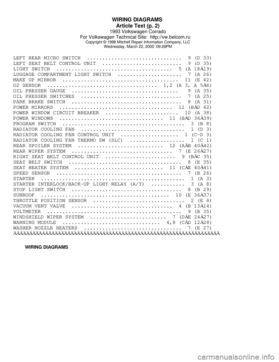
LEFT REAR MICRO SWITCH ............................... 9 (D 33)
LEFT SEAT BELT CONTROL UNIT .......................... 9 (D 35)
LIGHT SWITCH ...................................... 5 (A 18Ä19)
LUGGAGE COMPARTMENT LIGHT SWITCH ..................... 7 (A 26)
MAKE UP MIRROR ...................................... 11 (E 42)
O2 SENSOR .................................... 1,2 (A 3, A 5
Ä6)
OIL PRESSER GAUGE ................................... 9 (A 35)
OIL PRESSER SWITCHES ................................. 7 (A 25)
PARK BRAKE SWITCH .................................... 8 (A 31)
POWER MIRRORS ..................................... 11 (B
ÄD 42)
POWER WINDOW CIRCUIT BREAKER ........................ 10 (A 38)
POWER WINDOWS .................................. 11 (B
ÄD 36Ä39)
PROGRAM SWITCH ........................................ 3 (B 8)
RADIATOR COOLING FAN .................................. 1 (D 3)
RADIATOR COOLING FAN CONTROL UNIT ................... 1 (C-D 3)
RADIATOR COOLING FAN THERMO SW (SLC) .................. 1 (C 1)
REAR SPOILER SYSTEM ............................ 12 (A
ÄB 40Ä42)
REAR WIPER SYSTEM ................................. 7 (E 26
Ä27)
RIGHT SEAT BELT CONTROL UNIT ....................... 9 (B
ÄC 35)
SEAT BELT SWITCH ..................................... 8 (E 35)
SEAT HEATER SYSTEM ............................. 11 (C
ÄE 40Ä41)
SPEED SENSOR ......................................... 7 (B 26)
STARTER ............................................... 1 (A 3)
STARTER INTERLOCK/BACK-UP LIGHT RELAY (A/T) ........... 3 (A 8)
STOP LIGHT SWITCH .................................... 8 (B 29)
SUNROOF .......................................... 10 (E 36
Ä37)
THROTTLE POSITION SENSOR .............................. 2 (E 4)
VACUUM VENT VALVE ................................. 4 (B 13
Ä14)
VOLTMETER ............................................ 9 (B 35)
WINDSHIELD WIPER SYSTEM ......................... 7 (D
ÄE 24Ä27)
WARNING MODULE ................................ 4,8 (C
ÄD 12Ä28)
WASHER NOZZLE HEATERS ................................ 7 (E 27)
ÄÄÄÄÄÄÄÄÄÄÄÄÄÄÄÄÄÄÄÄÄÄÄÄÄÄÄÄÄÄÄÄÄÄÄÄÄÄÄÄÄÄÄÄÄÄÄÄÄÄÄÄÄÄÄÄÄÄÄÄÄÄÄÄÄ WIRING DIAGRAMS
Page 913 of 920

WIRING DIAGRAMS
Article Text (p. 7)
1993 Volkswagen Corrado
For Volkswagen Technical Site: http://vw.belcom.ru
Copyright © 1998 Mitchell Repair Information Company, LLC
Wednesday, March 22, 2000 09:28PMFig. 5: Fuse/Relay Panel, Ignition Sw, Lt Sw (Grid 16-19)
Page 914 of 920

WIRING DIAGRAMS
Article Text (p. 8)
1993 Volkswagen Corrado
For Volkswagen Technical Site: http://vw.belcom.ru
Copyright © 1998 Mitchell Repair Information Company, LLC
Wednesday, March 22, 2000 09:28PMFig. 6: Fuse/Relay Panel (Cont), A/C Sw (Grid 20-23)
Page 915 of 920

WIRING DIAGRAMS
Article Text (p. 9)
1993 Volkswagen Corrado
For Volkswagen Technical Site: http://vw.belcom.ru
Copyright © 1998 Mitchell Repair Information Company, LLC
Wednesday, March 22, 2000 09:28PMFig. 7: Fuse/Relay Panel (Cont), W/Shield Wiper Mtr (Grid 24-27)
Page 916 of 920

WIRING DIAGRAMS
Article Text (p. 10)
1993 Volkswagen Corrado
For Volkswagen Technical Site: http://vw.belcom.ru
Copyright © 1998 Mitchell Repair Information Company, LLC
Wednesday, March 22, 2000 09:28PMFig. 8: Fuse/Relay Panel (Cont), Warning Module (Grid 28-31)
Page 918 of 920

WIRING DIAGRAMS
Article Text (p. 12)
1993 Volkswagen Corrado
For Volkswagen Technical Site: http://vw.belcom.ru
Copyright © 1998 Mitchell Repair Information Company, LLC
Wednesday, March 22, 2000 09:28PMFig. 10: Fuse/Relay Panel Layout, Sunroof Sw (Grid 36-39)