relay VOLKSWAGEN CORRADO 1993 Service Manual
[x] Cancel search | Manufacturer: VOLKSWAGEN, Model Year: 1993, Model line: CORRADO, Model: VOLKSWAGEN CORRADO 1993Pages: 920, PDF Size: 6.92 MB
Page 477 of 920

ELECTRICAL COMPONENT LOCATOR
Article Text (p. 19)
1993 Volkswagen Corrado
For Volkswagen Technical Site: http://vw.belcom.ru
Copyright © 1998 Mitchell Repair Information Company, LLC
Wednesday, March 22, 2000 09:09PMPower Window Control Unit Behind trim panel on rear
pillar of left door.Seat Belt Warning Control Unit In fuse/relay panel, behind
left side of dash.
Page 509 of 920
E - THEORY/OPERATION
Article Text (p. 4)
1993 Volkswagen Corrado
For Volkswagen Technical Site: http://vw.belcom.ru
Copyright © 1998 Mitchell Repair Information Company, LLC
Wednesday, March 22, 2000 09:09PM
Fuel Injectors
See FUEL CONTROL under FUEL SYSTEM in this article.
Fuel Pump
See FUEL DELIVERY under FUEL SYSTEM in this article.
Idle Air Control/Stabilizer Valve
See IDLE SPEED under FUEL SYSTEM in this article.
Ignition Coil & Output Stage
See DISTRIBUTORLESS IGNITION SYSTEM (DIS) under IGNITION
SYSTEM in this article.
Malfunction Indicator (CHECK ENGINE) Light
See MALFUNCTION INDICATOR (CHECK ENGINE) LIGHT under SELF-
DIAGNOSTIC SYSTEM in this article.
FUEL SYSTEM
FUEL DELIVERY
Fuel Pump
A 2-stage fuel pump, located in fuel tank, is used (one motor
drives two separate pumps). The stage one vane-type pump draws fuel,
through a screen, from bottom of fuel tank and into an accumulator.
The vane-type pump acts as a transfer pump. The stage two gear-type
pump draws fuel from bottom of accumulator and out fuel lines.
Fuel Pressure Regulator
The diaphragm-type fuel pressure regulator is attached to
fuel return side of fuel rail. Fuel pressure is regulated depending on
intake manifold pressure. As intake manifold pressure changes, the
pressure regulator will increase or decrease fuel system pressure.
FUEL CONTROL
Fuel Injectors
Fuel injectors are supplied with battery (system) voltage
through power supply relay and are controlled (grounded) by the ECM.
Injectors are opened sequentially in cylinder firing order. Fuel
quantity is determined by injector on time (duty cycle).
IDLE SPEED
Idle Air Control/Stabilizer Valve
The idle air control/stabilizer valve is actuated by the ECM
thorough the valve's ground control circuit. When a defect in circuit
is recognized, both output stages are shut-off and the valve rotates
to a fixed potion. This permits engine to idle at a warm engine idle
speed.
IGNITION SYSTEM
Page 511 of 920
E - THEORY/OPERATION
Article Text (p. 6)
1993 Volkswagen Corrado
For Volkswagen Technical Site: http://vw.belcom.ru
Copyright © 1998 Mitchell Repair Information Company, LLC
Wednesday, March 22, 2000 09:09PM
EMISSION SYSTEMS
AIR INJECTION SYSTEM
The air injection system consists of electrically operated
air pump, inlet valve, shut-off valve (mounted between intake ports
for cylinders No. 2 and 4), and air pump control relay.
The Electronic Control Module (ECM) control operation of air
injection system air pump by completing the ground circuit of the air
pump control relay (located above brake master cylinder). In addition,
the relay operates the secondary air injection inlet valve.
EXHAUST GAS RECIRCULATION (EGR) SYSTEM
The EGR system consist of EGR valve, EGR frequency valve, and
EGR temperature sensor. All Corrado SLC models are equipped with the
EGR system. The EGR system is switched on when engine coolant
temperature reaches 122øF (50øC). The system recirculates a small
portion of exhaust gas into the intake air/fuel mixture to reduce
nitrous oxide emissions (NOx).
EGR Frequency Valve
The EGR frequency valve is mounted on back of intake
manifold. The frequency valve controls the amount of vacuum supplied
to the EGR valve. The ECM, depending on engine speed and load,
controls the frequency valve's ground circuit. In doing so, the ECM
controls the amount of recirculated exhaust gas entering the engine.
EGR Temperature Sensor
Sensor is located in EGR valve exhaust gas recirculation
channel. The EGR temperature sensor measures exhaust gas temperature.
The electrical resistance of the sensor decreases as the temperature
of the exhaust gas increases. The signal generated by the EGR
temperature sensor is ONLY used for diagnosis of the EGR system.
FUEL EVAPORATIVE EMISSIONS SYSTEM
Fuel Evaporative (Frequency) Valve
The ECM determines the duty cycle of the frequency valve to
regulate the flow of fuel vapors from fuel evaporative (carbon)
canister into engine. When no current is supplied to valve, it remains
in the open position. The valve is closed (100% duty cycle) when the
engine is started cold. A spring operated check valve inside the
frequency valve closes when the engine is off. This prevents fuel
vapors from entering intake manifold and causing a rich mixture during
engine restart.
Fuel Tank Venting
The engine speed, engine load, engine coolant temperature,
and throttle valve potentiometer input signals are used by the ECM to
control fuel tank venting. Fuel vapors from fuel tank are vented to
fuel evaporative (carbon) canister. When engine is warm and above idle
Page 569 of 920
F - BASIC TESTING
Article Text (p. 4)
1993 Volkswagen Corrado
For Volkswagen Technical Site: http://vw.belcom.ru
Copyright © 1998 Mitchell Repair Information Company, LLC
Wednesday, March 22, 2000 09:10PM
kg/cmý). Turn engine off. After 10 minutes, residual pressure should
be 29 psi (2 kg/cm
ý). If system pressure is too high, replace fuel
pressure regulator.
3) If residual pressure is too low, operate engine until
system pressure builds up, then pinch off Blue fuel return line. If
pressure holds, replace the fuel regulator. If fuel pressure is low,
check for leaks at fuel lines, fuel injectors and fuel pump check
valve
TRANSFER PUMP CHECK
Transfer Pump Fuel Volume Check
1) Turn ignition off. To check transfer pump (in tank),
remove rear seat. Remove fuel sending unit access cover. Disconnect
ignition coil secondary wire and jumper to ground.
2) With transmission in Neutral, crank engine for 3-4
seconds. While starter is turning and for a few seconds afterwards, an
audible sound should be heard at the pump. If sound is not heard, go
to next step. If sound is heard, go to step 5).
3) Remove fuel pump relay from relay panel. On Corrado and
Passat, activate fuel pumps using Remote Control (VAG 1348/3A). On all
other models, activate fuel pumps using Remote Control (US 4480/3). On
all models, if pump does not operate, remove transfer pump wire
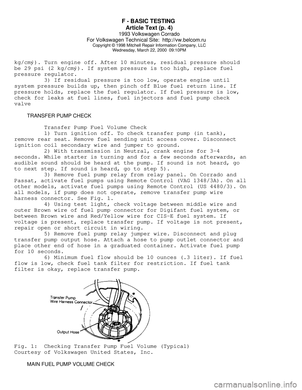
harness connector. See Fig. 1.
4) Using test light, check voltage between middle wire and
outer Brown wire of fuel pump connector for Digifant fuel system, or
between Brown wire and Red/Yellow wire for CIS-E fuel system. If
voltage is present, replace transfer pump. If voltage is not present,
repair open or short circuit in wiring.
5) Remove fuel pump relay jumper wire. Disconnect and plug
transfer pump output hose. Attach a hose to pump outlet connector and
place other end of hose in a graduated container. Activate fuel pump
for 10 seconds.
6) Minimum fuel flow should be 10 ounces (.3 liter). If fuel
flow is low, check fuel tank filter for restriction. If fuel tank
filter is okay, replace transfer pump.Fig. 1: Checking Transfer Pump Fuel Volume (Typical)
Courtesy of Volkswagen United States, Inc.
MAIN FUEL PUMP VOLUME CHECK
Page 570 of 920
F - BASIC TESTING
Article Text (p. 5)
1993 Volkswagen Corrado
For Volkswagen Technical Site: http://vw.belcom.ru
Copyright © 1998 Mitchell Repair Information Company, LLC
Wednesday, March 22, 2000 09:10PM
NOTE: Before testing main fuel pump, check transfer pump. See
TRANSFER PUMP CHECK.
Cabriolet, Fox, Golf & Jetta
Remove fuel pump relay from relay panel. Activate fuel pumps
using Remote Control (US 4480/3). Activate fuel pumps for 30 seconds.
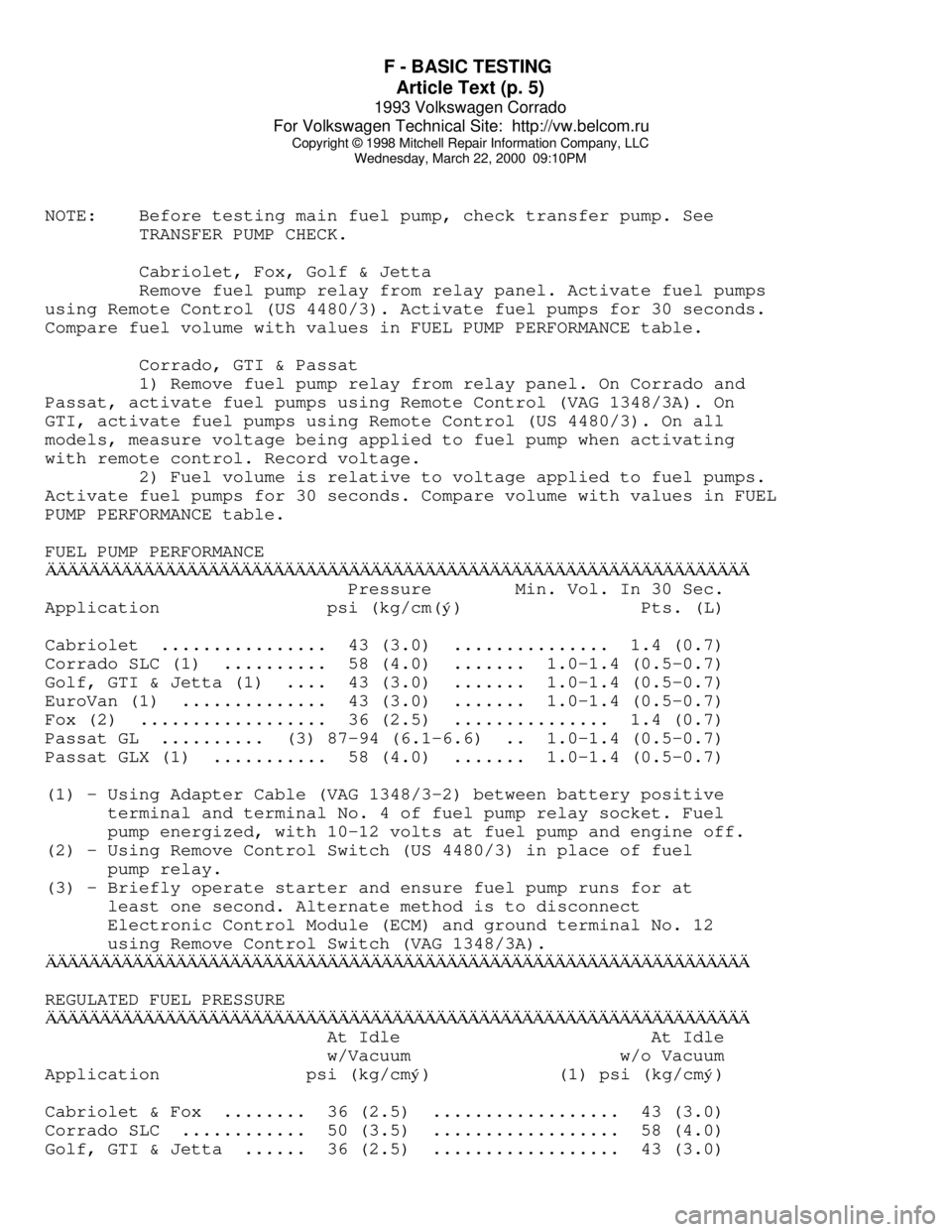
Compare fuel volume with values in FUEL PUMP PERFORMANCE table.
Corrado, GTI & Passat
1) Remove fuel pump relay from relay panel. On Corrado and
Passat, activate fuel pumps using Remote Control (VAG 1348/3A). On
GTI, activate fuel pumps using Remote Control (US 4480/3). On all
models, measure voltage being applied to fuel pump when activating
with remote control. Record voltage.
2) Fuel volume is relative to voltage applied to fuel pumps.
Activate fuel pumps for 30 seconds. Compare volume with values in FUEL
PUMP PERFORMANCE table.
FUEL PUMP PERFORMANCEÄÄÄÄÄÄÄÄÄÄÄÄÄÄÄÄÄÄÄÄÄÄÄÄÄÄÄÄÄÄÄÄÄÄÄÄÄÄÄÄÄÄÄÄÄÄÄÄÄÄÄÄÄÄÄÄÄÄÄÄÄÄÄÄÄ Pressure Min. Vol. In 30 Sec.
Application psi (kg/cm(
ý) Pts. (L)
Cabriolet ................ 43 (3.0) ............... 1.4 (0.7)
Corrado SLC (1) .......... 58 (4.0) ....... 1.0-1.4 (0.5-0.7)
Golf, GTI & Jetta (1) .... 43 (3.0) ....... 1.0-1.4 (0.5-0.7)
EuroVan (1) .............. 43 (3.0) ....... 1.0-1.4 (0.5-0.7)
Fox (2) .................. 36 (2.5) ............... 1.4 (0.7)
Passat GL .......... (3) 87-94 (6.1-6.6) .. 1.0-1.4 (0.5-0.7)
Passat GLX (1) ........... 58 (4.0) ....... 1.0-1.4 (0.5-0.7)
(1) - Using Adapter Cable (VAG 1348/3-2) between battery positive
terminal and terminal No. 4 of fuel pump relay socket. Fuel
pump energized, with 10-12 volts at fuel pump and engine off.
(2) - Using Remove Control Switch (US 4480/3) in place of fuel
pump relay.
(3) - Briefly operate starter and ensure fuel pump runs for at
least one second. Alternate method is to disconnect
Electronic Control Module (ECM) and ground terminal No. 12
using Remove Control Switch (VAG 1348/3A).
ÄÄÄÄÄÄÄÄÄÄÄÄÄÄÄÄÄÄÄÄÄÄÄÄÄÄÄÄÄÄÄÄÄÄÄÄÄÄÄÄÄÄÄÄÄÄÄÄÄÄÄÄÄÄÄÄÄÄÄÄÄÄÄÄÄREGULATED FUEL PRESSURE
ÄÄÄÄÄÄÄÄÄÄÄÄÄÄÄÄÄÄÄÄÄÄÄÄÄÄÄÄÄÄÄÄÄÄÄÄÄÄÄÄÄÄÄÄÄÄÄÄÄÄÄÄÄÄÄÄÄÄÄÄÄÄÄÄÄ At Idle At Idle
w/Vacuum w/o Vacuum
Application psi (kg/cm
ý) (1) psi (kg/cmý)
Cabriolet & Fox ........ 36 (2.5) .................. 43 (3.0)
Corrado SLC ............ 50 (3.5) .................. 58 (4.0)
Golf, GTI & Jetta ...... 36 (2.5) .................. 43 (3.0)
Page 579 of 920
FUSES & CIRCUIT BREAKERS
Article Text
1993 Volkswagen Corrado
For Volkswagen Technical Site: http://vw.belcom.ru
Copyright © 1998 Mitchell Repair Information Company, LLC
Wednesday, March 22, 2000 09:11PM
ARTICLE BEGINNING
1990-94 ELECTRICAL
Volkswagen Fuses & Circuit Breakers
Corrado
FUSES & CIRCUIT BREAKERS
FUSE PANEL LOCATION
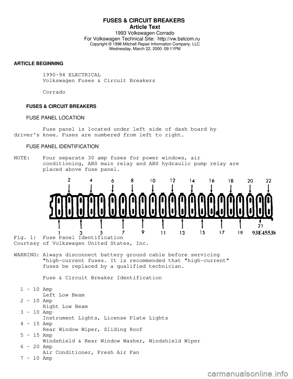
Fuse panel is located under left side of dash board by
driver's knee. Fuses are numbered from left to right.
FUSE PANEL IDENTIFICATION
NOTE: Four separate 30 amp fuses for power windows, air
conditioning, ABS main relay and ABS hydraulic pump relay are
placed above fuse panel.Fig. 1: Fuse Panel Identification
Courtesy of Volkswagen United States, Inc.
WARNING: Always disconnect battery ground cable before servicing
"high-current fuses. It is recommended that "high-current"
fuses be replaced by a qualified technician.
Fuse & Circuit Breaker Identification
1 - 10 Amp
Left Low Beam
2 - 10 Amp
Right Low Beam
3 - 10 Amp
Instrument Lights, License Plate Lights
4 - 15 Amp
Rear Window Wiper, Sliding Roof
5 - 15 Amp
Windshield & Rear Window Washer, Windshield Wiper
6 - 20 Amp
Air Conditioner, Fresh Air Fan
7 - 10 Amp
Page 586 of 920
G - TESTS W/CODES
Article Text (p. 4)
1993 Volkswagen Corrado
For Volkswagen Technical Site: http://vw.belcom.ru
Copyright © 1998 Mitchell Repair Information Company, LLC
Wednesday, March 22, 2000 09:11PM
Exceeded
00585 (2411) ... EGR Temperature Sensor ...... Short Ckt To Ground
Or Faulty Sensor
00586 (----) ........ EGR Control ........ EGR Valve Sticking Open
01025 (----) .. Malfunction Indicator Light .... Open/Short Ckt To
Ground Or Battery
Voltage
01242 (4332) ...... ECM Output Stage ........ Faulty Ckt To Output
Check Controlled
Components
01247 (4343) ... EVAP Frequency Solenoid ...... Open/Short Ckt To
Ground Or Battery
Voltage
01249 (4411) ....... Injector No. 1 ............ Open/Short Ckt To
Ground Or Battery
Voltage
01250 (4412) ....... Injector No. 2 ............ Open/Short Ckt To
Ground Or Battery
Voltage
01251 (4413) ....... Injector No. 3 ............ Open/Short Ckt To
Ground Or Battery
Voltage
01252 (4414) ....... Injector No. 4 ............ Open/Short Ckt To
Ground Or Battery
Voltage
01253 (4415) ....... Injector No. 5 ............ Open/Short Ckt To
Ground Or Battery
Voltage
01254 (4422) ....... Injector No. 6 ............ Open/Short Ckt To
Ground Or Battery
Voltage
01257 (4431) .. Idle Air Control (IAC) Valve ... Open/Short Ckt To
Ground Or Battery
Voltage
01259 (4433) ....... Fuel Pump Relay ....... Open Ckt Or Short Ckt
To Battery Voltage
01265 (4312) .. EGR Frequency (2-Way) Valve .... Open/Short Ckt To
Ground Or Battery
Voltage
65535 (1111) ... Electronic Control Module .... Replace Faulty ECM
(1) - For testing information, see J - PIN VOLTAGE CHARTS article.
(2) - Blink code is 4-digit malfunction indicator CHECK ENGINE
light code.
(3) - Check intake and exhaust systems for leaks. Check for too low
or too high a fuel pressure. Also check for malfunctioning
fuel injectors or engine misfire.
(4) - Check intake and exhaust systems for leaks. Check for mass
airflow sensor hot wire not burning off cleanly. Check for
faulty oxygen sensor control and for EVAP frequency solenoid
sticking open. Also check for malfunctioning fuel injectors or
engine misfire.
Page 588 of 920

G - TESTS W/CODES
Article Text (p. 6)
1993 Volkswagen Corrado
For Volkswagen Technical Site: http://vw.belcom.ru
Copyright © 1998 Mitchell Repair Information Company, LLC
Wednesday, March 22, 2000 09:11PM
Corrado SLC (2.8L)
1) Connect Scan Tester (VAG 1551) to Data Link Connectors
(DLC) located in center console, in front of shift lever. With scan
tester in OUTPUT DIAGNOSTIC TEST MODE, the injectors, Idle Air Control
(IAC) valve, evaporative frequency (solenoid) valve, oxygen sensor
relay, and EGR frequency valve (if equipped) may be actuated in
sequence listed.
2) The injector(s) must click by opening and closing
throttle. To trigger injectors 2 through 6, open and close throttle
once for each injector. If injector(s) do(es) not click, test
circuit(s) using the J - PIN VOLTAGE CHARTS article.
3) If injectors are okay, switch to next output test by
pressing the right arrow button. Press right arrow button to actuate
IAC valve. IAC valve must pulsate noticeably until switched to next
output test by pressing the right arrow button.
4) If IAC valve does not pulsate, turn ignition off.
Disconnect IAC valve and connect LED Tester (US 1115) to IAC valve
wiring harness connector using jumper wires from Adapter Kit (VW
1594).
5) Turn ignition on and repeat IAC valve output test. If LED
blinks, replace IAC valve. If LED does not blink, test circuit using
the J - PIN VOLTAGE CHARTS article in this section. If IAC and circuit
are okay, replace ECM.
6) If IAC valve pulsates properly, locate evaporative
frequency solenoid valve (located behind air cleaner housing, on
wheelwell). Disconnect hose, coming from fuel vapor canister, from
frequency solenoid. Attach auxiliary hose to solenoid.
7) Blow into auxiliary hose, in direction of throttle
housing, while performing solenoid output test (pressing right arrow
button to actuate evaporative frequency solenoid). If solenoid does
not actuate (open and close), disconnect wiring harness from solenoid.
Connect LED tester to solenoid wiring harness connector using jumper
wires from adapter kit.
8) Repeat evaporative solenoid valve output test. If LED
blinks, replace evaporative frequency solenoid valve. If LED does not
blink, test circuit using the J - PIN VOLTAGE CHARTS article. If
evaporative solenoid valve and circuit are okay, replace ECM.
9) If evaporative frequency solenoid operates properly, press
right arrow button to actuate oxygen sensor relay (mounted on
fuse/relay panel with a clip). If relay does not click, test relay and
its circuit using the J - PIN VOLTAGE CHARTS article.
10) If relay operates properly, press right arrow button to
actuate EGR frequency valve. Frequency valve must click until test
mode is switched to next output test by pressing the right arrow
button.
11) If frequency valve does not click, disconnect valve.
Connect LED tester using jumper wires from Adapter Kit (VAG 1594) to
frequency valve wiring harness connector.
12) If LED blinks, replace EGR frequency valve. If LED does
not blink, test circuit using the J - PIN VOLTAGE CHARTS article. If
EGR frequency valve and circuit are okay, replace ECM.
13) If EGR frequency valve operates properly, press right
Page 599 of 920
H - TESTS W/O CODES
Article Text (p. 3)
1993 Volkswagen Corrado
For Volkswagen Technical Site: http://vw.belcom.ru
Copyright © 1998 Mitchell Repair Information Company, LLC
Wednesday, March 22, 2000 09:11PM
NOTE: Symptoms listed are for CIS-E Motronic system. When working
on Digifant and Motronic systems, use symptoms listed only
as a diagnostic guide. A list of specific symptoms for
Digifant and Motronic systems is not available from
manufacturer.
ENGINE DOES NOT START OR IS DIFFICULT TO START WHEN COLD
* Check for insufficient fuel in tank.
* Check fuel pump relay and fuel pump.
* Check fuel system for leaks.
* Check auxiliary air intake system.
* Check fuel system after-start, acceleration enrichment and
warm-up circuits.
* Check cold-start valve.
* Check airflow sensor lever adjustment and control plunger.
* Check sensor plate rest position and idle circuit.
* Check fuel system differential and residual pressures.
* Check fuel injection volume.
* Check engine coolant temperature sensor.
* Check ignition timing, spark plugs, distributor, secondary
ignition wiring and coil.
* Check Hall Effect sensor.
* Check ignition coil power output stage.
ENGINE DOES NOT START OR IS DIFFICULT TO START WHEN WARM
* Check radiator cooling fan after-run circuit.
* Check fuel pump check valve.
* Check fuel evaporative frequency solenoid(s).
* Check fuel system for leaks.
* Check auxiliary air intake system.
* Check idle speed.
* Check fuel system after-start, acceleration enrichment and
warm-up circuits.
* Check cold-start valve.
* Check injector fuel pressure and volume.
* Check sensor plate rest position and idle circuit.
* Check sealing ring under control plunger.
* Check fuel system differential and residual pressures.
* Check engine coolant temperature sensor.
* Check ignition timing, spark plugs, distributor, secondary
ignition wiring and coil.
UNEVEN IDLE OR NO IDLE WITH COLD ENGINE OR DURING WARM-UP
* Check fuel evaporative frequency solenoid(s).
* Check fuel system for leaks.
* Check auxiliary air intake system.
* Check idle speed.
* Check oxygen sensor control circuit.
Page 600 of 920
H - TESTS W/O CODES
Article Text (p. 4)
1993 Volkswagen Corrado
For Volkswagen Technical Site: http://vw.belcom.ru
Copyright © 1998 Mitchell Repair Information Company, LLC
Wednesday, March 22, 2000 09:11PM
* Check cold-start valve.
* Check injector fuel pressure and volume.
* Check throttle potentiometer.
* Check fuel system differential and residual pressures.
* Check idle switch.
* Check engine coolant temperature sensor.
* Check exhaust system.
* Check ignition timing and spark plugs.
ENGINE STARTS BUT STALLS
* Check fuel pump relay and fuel pump.
* Check auxiliary air intake system.
* Check idle speed.
* Check fuel system after-start, acceleration enrichment and
warm-up circuits.
* Check airflow sensor lever adjustment and control plunger.
* Check sensor plate rest position and idle circuit.
* Check fuel system differential and residual pressures.
* Check idle switch.
* Check engine coolant temperature sensor.
IDLE SPEED EXCEEDS SPECIFICATION
* Check throttle cable adjustment.
* Check fuel evaporative frequency solenoid(s).
* Check auxiliary air intake system.
* Check idle speed.
* Check throttle potentiometer.
* Check idle switch.
* Check engine coolant temperature sensor.
* Check throttle body basic adjustment.
* Check ignition timing.
POOR ACCELERATION WITH COLD ENGINE OR DURING WARM-UP
* Check fuel pump.
* Check auxiliary air intake system.
* Check oxygen sensor control circuit.
* Check fuel system after-start, acceleration enrichment and
warm-up circuits.
* Check airflow sensor lever adjustment and control plunger.
* Check throttle potentiometer.
* Check fuel system differential and residual pressures.
* Check injector fuel pressure and volume.
* Check idle switch.
* Check engine coolant temperature sensor.
* Check throttle body basic adjustment.
* Check exhaust system.
* Check ignition timing, spark plugs, distributor, secondary
ignition wiring and coil.