lock VOLKSWAGEN GOLF 1993 1H / 3.G User Guide
[x] Cancel search | Manufacturer: VOLKSWAGEN, Model Year: 1993, Model line: GOLF, Model: VOLKSWAGEN GOLF 1993 1H / 3.GPages: 156, PDF Size: 6.36 MB
Page 17 of 156
Downloaded from www.Manualslib.com manuals search engine L-___________________________________________________~~~_CONTROLS AND EQUIPMENT
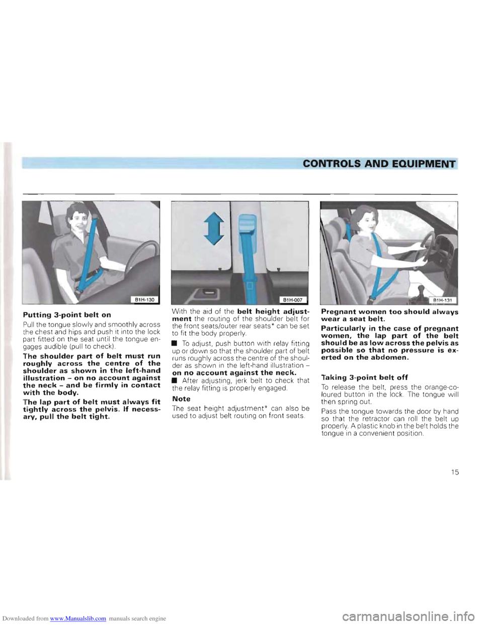
Putting 3-point belt on
Pull the tongue slowly and smoothly across
t he chest and hips and push it into the lock
part fitted on the
seat unti l the tongue en
gages audible (pull to c heck)
The shoulder part of belt must run roughly across the centre of the shoulder as shown in the left-hand illustration -on no account against the neck -and be firmly in contact with the body.
T he lap part of belt must always fit tightly across the pelvis. If necessary, pull the belt tight.
With the aid of the belt height adjustment the routing of the shou lder belt for
the fron t seats/outer rear seat s * can be set
t o fit the body properly.
• T o
adJUSt. push button with re la y fitting
up or down so that the shoulder part of be lt
runs rough ly across the cen tre of the shoul
der as shown i n the le ft-h and illustration on no account against the neck. • After adjustin g, jerk belt to check that
the relay fitting is properly engaged.
Note
The seat height adjustment' can also be
used to adju st be lt routing on front seats.
Pregnant women too should always
wear a seat belt.
Particularly in the case of pregnant
women, the lap part of the belt
should be as low across the pelvis as
possible so that no pressure is ex
erted on the abdomen.
Taking 3-point belt off
To re lease the belt, press the orange-co
l oured button in the lock . T he to ngue will
th en s pring out.
Pass the tongue
towards the door by hand
so that the retractor can roll the belt up
prope
rly . A plastic knob in the belt holds the
t o ngue in a convenient position .
15
Page 18 of 156
Downloaded from www.Manualslib.com manuals search engine CONTROLS AND EQUIPMENT
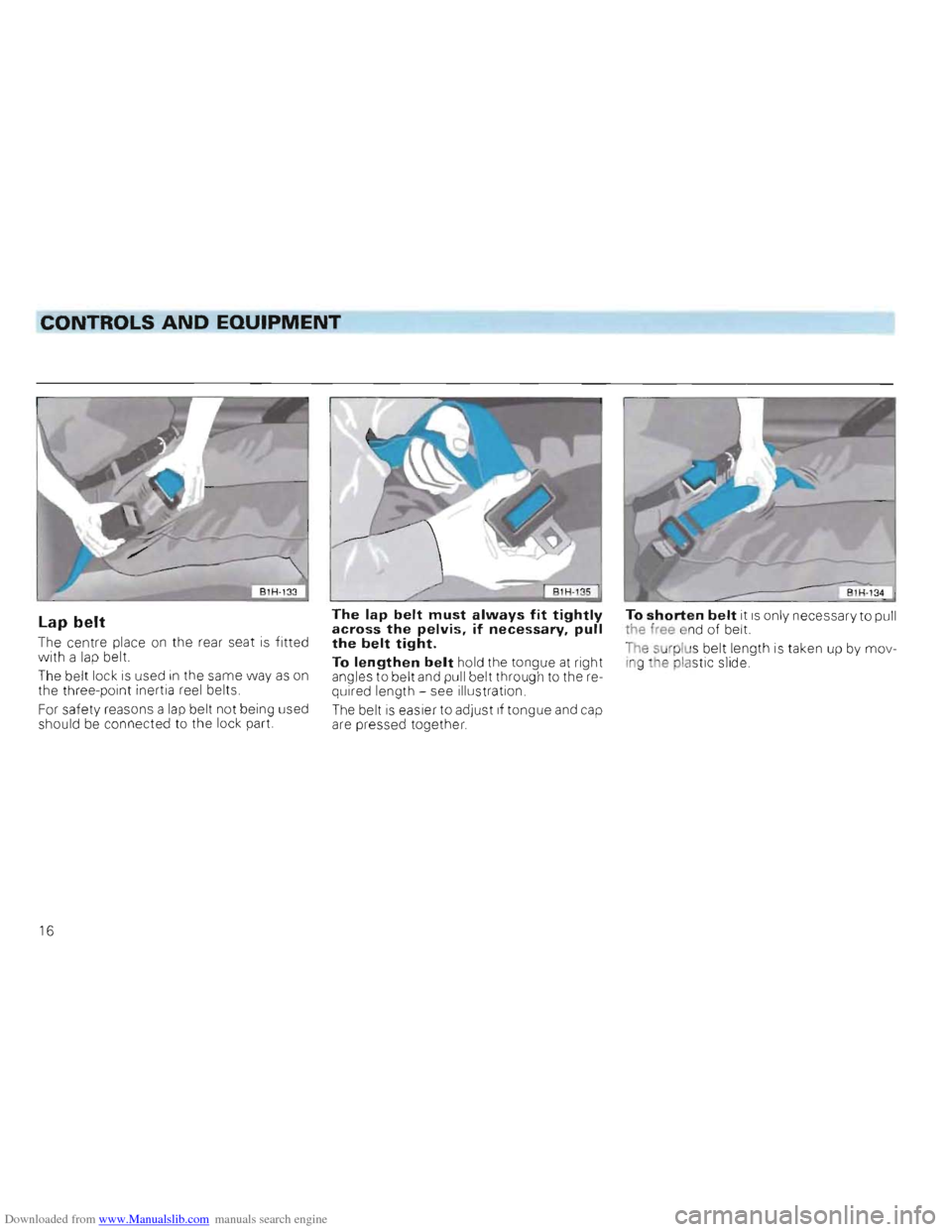
Lap belt
The centre place on the rear seat is fitted
with a lap belt.
Th e belt lock is used in the same way as on
the three-point inertia reel belts.
For safety reasons a
lap belt not being used
shou ld be connected to the lock part.
The lap belt must always fit tightly across the pelvis, if necessary, pull the belt tight.
To lengthen belt hold the tongue at right
angles to belt and pull belt through to the required length -see illustration.
The belt
is easier to adjust if tongue and cap
are pressed together.
To sh orten belt it is only necess ary to pull the free end of belt.
The sur plu s be lt length is taken up by mov
Ing the plastic slid e.
16
Page 28 of 156
Downloaded from www.Manualslib.com manuals search engine CONTROLS AND EQUIPMENT
2 -Adjusting backrest angle
Take weight off back rest and turn knob.
The backrest of the driv er's seat shou ld be adjusted so that the top of the steerin g
whee l can be reached with the arms angled slightly.
Attention
Do not lower the backrest too far
when on the move because the seat belts are then no longer fully effective.
3 -Releasing backrest
(2 door vehicl es only)
Lif t the
lever (also belt holder) and move the
back rest forward. Before releasing the
backrest pull
belt out of the belt holder (see
page 17).
Attention For safety reasons, ensure that the backrest lock is engaged when the vehicle is moving!
4 -Adjusting angle of the seat
cushion*
If the angle of the seat cushion is to be changed, pull lever up and bring seat
cushion to the desired angle by placing
mo
re or less weight on the backrest.
5 -Adjusting seat height*
Take weight off seat cushion and pull up lever. The whole seat cushion moves up
war ds. To adjust the seat cushion down
w ards, push seat downwards with body
weight.
Attention • For safety reasons the height of the driver's seat must only be adjusted when vehicle is stationary. • Be careful when adjusting the seat height! Careless and uncontrolled adjustment can cause injuries.
6 -Adjusting lumbar support
By turn ing the hand-wheel the seat padding in the lumbar area of the spine can be made
to arch forward slightly. This gives effective
support to the natura l curvatu re of the spine
so that t
he sitting position is less fatigui ng ,
particul arly on long trips
26
Page 32 of 156
Downloaded from www.Manualslib.com manuals search engine CONTROLS AND EQUIPMENT
Luggage compartment cover / Folding/sliding cover*
Articles of clothing can be placed on the luggage compartment cover.
Attention Do not place heavy hard articles on the luggage compartment cover or folding/sliding cover they could endanger the vehicle occupants or damage the folding/sliding cover if the brakes are applied suddenly_
Furthermore, the heater element wires in
the heated rear window could be damaged
by articles rubbing against them.
The folding/s liding cover
can be pushed to
gether to the front or rear .
When the tailgate of the saloo n is opened ,
the luggage compartment cover is also
lifted .
If large items of lug gag e are to be carried,
the cover
can be removed:
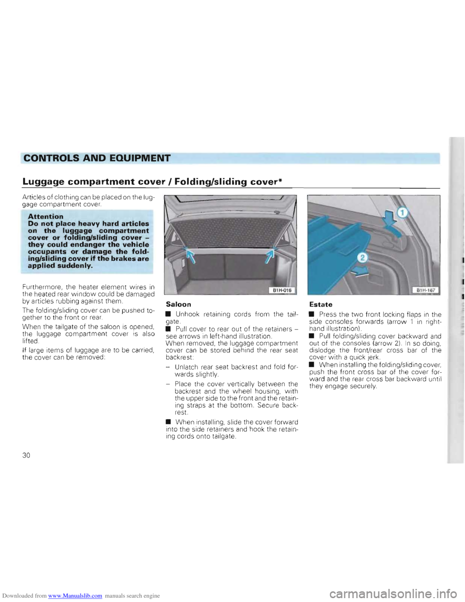
Saloon
• Unhook retaining cords fro m the tailgate.
• Pull cover to rear out of the retainers
see arrow s in left-hand illustration.
When removed, the luggag e co mpartment
cover
can be stored behind the rear seat
backrest:
- Unlat
ch rear seat backrest and fold for
wards slightly.
- Place the cove r vertically between the back rest and the wheel housing, with the upper side to the front and the retain
ing straps at the bottom. Secu re back
r est.
• When installing , slide the cover forward
into the side retainers and hook the retain
ing cords onto tailgate.
Estate
• Press the two front locking flaps in the
side consoles forwards (arrow 1 in right
hand illus tration).
•
Pull fo lding/sliding cover backward and out of the consoles (arrow 2) I n so doing,
dislodge th e front/ rear cross bar of the
cover with a qUi ck jerk.
• When
installing the folding/s liding cover, push the front cross bar of the cover for
ward and the rear cross ba r backward un til
the y engage securely.
30
Page 33 of 156
Downloaded from www.Manualslib.com manuals search engine CONTROLS AND EaUIPMENT ------------------------------~---
Pedals
- _ movement of the peda ls must never be ~S ncted .
::-thIs reason, do not put articles in the '00 well which cou ld roll or slide under
- 3ath th e pedals.
-
he case of defects on the brake sys
'em, a greater pedal travel may be necessa , t should always be possib le to depress
- "'e clut ch and acce le rator pedals fully.
All peda ls must be able to return , unh in-Jere d, to their rest positions. .
= o r these reasons, the only foot mats which e 'Y'\ay be used are those which leave the
ed al area compl ete ly free and which are pre ve nted from slipping .
'11
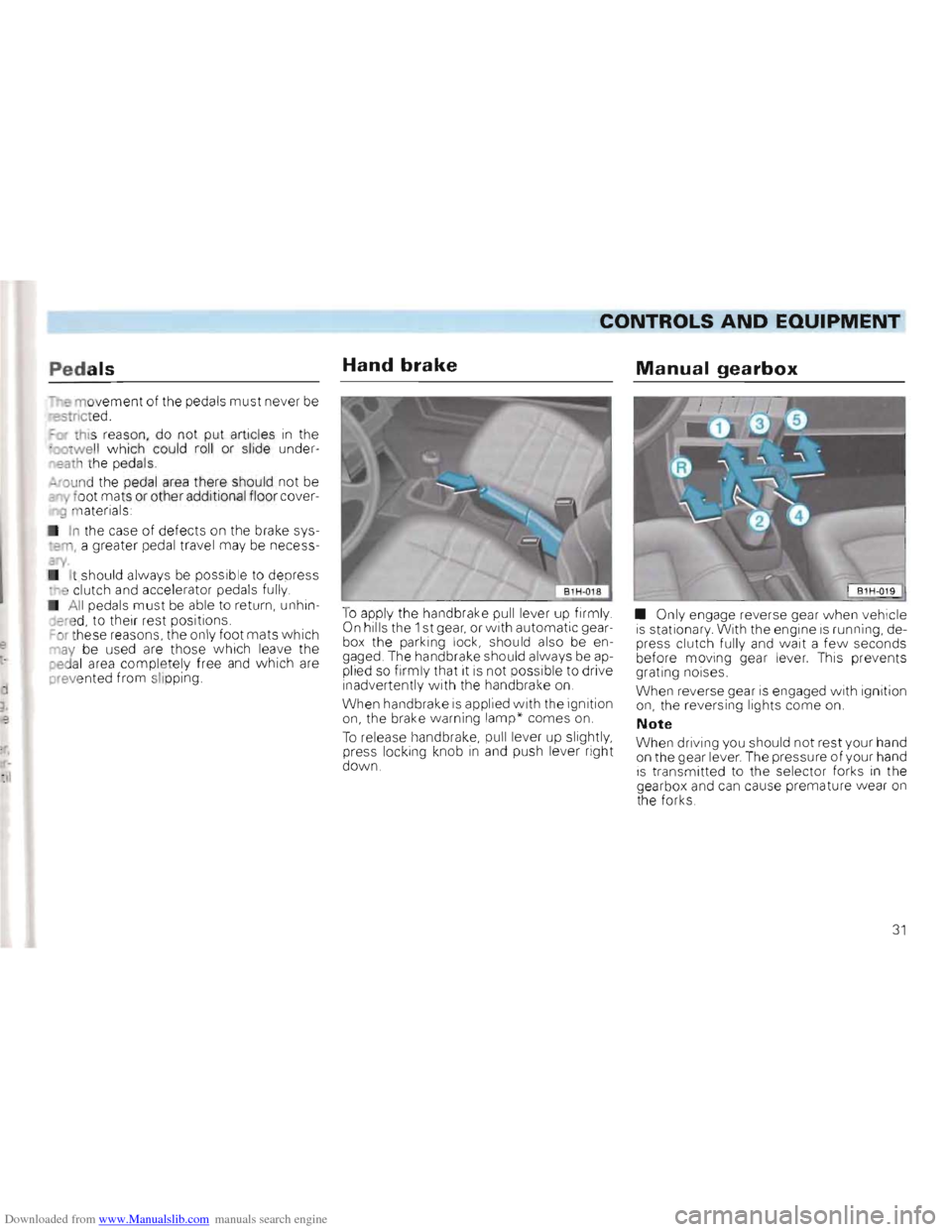
Hand brake
To apply the handbrake pull lever up firmly . On hills th e 1 st gear, or with automatic gear
box the parking lock, sho uld also be en
gaged. The handbrake should a lways be applied so firmly that it is not possible to drive inadve rtentl y with the handbrake on.
W h
en handbrake is applied with the ignition on, the brake warning lam p* comes on.
To release handbrake, pu ll lev er up slightly ,
press locking knob in and push lever right
do w n.
Manual gearbox
• Only engage reverse gear when vehicle is st ationary With the engin e is running, de
press clutch fully and wait a fe w seconds before mo ving gear lever. ThiS prevents
g rating noises .
When
rev erse gear is engaged with ignition on , the reversing lights come on.
Note
When driving you shou ld not rest your hand
on th e gear lever . The pressure of your hand is transmitted to the selector forks In the
gearb ox and can cause premature wear on the forks .
31
Page 34 of 156
Downloaded from www.Manualslib.com manuals search engine Automatic gearbox*
Driving programmes
The gearbox control unit is equipped with two driving programmes:
• Sport programme
• Economy programme
The programme is selected automatically depending on operation of the accel
erator pedal.
The sport programme is selected if the
accelerator pedal is operated rapidly. In this
case the accelerator pedal need not be de
pressed to the point of kick-down (see
Page 33). In the sport programme, full use is made of the engine's power reserves
through delayed change to higher gear
The
economy programme is selected
when the acce lerator, pedal is operated
s lowly or normally. Fuel consumption is reduced by changing early into higher gear and later into lower.
Selector lever lock
In positions "P" and " N" with the ignition
s wi tc h on the selector lever is locked . To move the selector lever out of these posi
t ions the brake pedal must be depressed and the selector lever button pushed in .
This prevents a gear being engaged inadver
tently
and the vehicle unintentional ly mov
ing off .
A de l
ay circuit prevents the selector lever
f rom locking when it is moved quickly past the" N" position (for Instan ce from" R" to "
D " ) This enables for examp
le the vehicle
to be " rocked" out of a "bogged down "
position The shift lock only locks the selec
tor
leve r if it is left in the " N" position for
more than about 1 second without the
brake pedal being depressed.
At speeds above 5 km/h the selector lever
is automatically switched-off in position "N".
Selector lever positions
P -Parking lock
The driving wheels are lock ed mechanically
The parking lock may only be engaged
when the vehicle is stationary. Before mov
ing the lever in or out of the" P" position the
lock button in the selector lever handle
must be pressed. Before moving the selec
tor lever out of
the" P" pOSition, the brake
pedal must also be depressed w hen the
ignition is switched on .
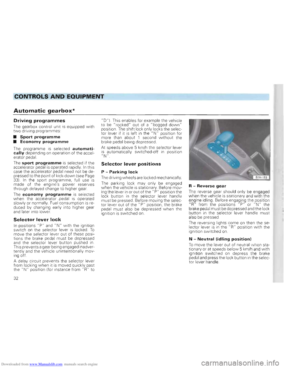
R -Reverse gear
The reverse gear should only be engaged
when the vehicle is station ary and with the
eng ine id ling. Before engaging the position
"R " from the positions "P" or "N " the
brake pedal must be d epr essed and the lock
b u tton in the selecto r lever handle must
also be p re ssed .
The
reversing lights come on then the se
l e cto r leve r is in the "R" position with the
ignition switched on.
N -Neutral (idling position)
To move the leve r out of neutral when sta
tionary or at speeds below 5 km/h and with
ignit ion switc hed on depress the brake
ped al and press the lock button in the selec
t or lever handle .
32
Page 35 of 156
Downloaded from www.Manualslib.com manuals search engine ___________C~NTROLS AND EQUIPMENT"----O_
D -Normal driving position
-e four forward gears are shifted up and
~own automatically depending upon engine
:lad and road speed.
J n d er certain driving condit ions it
is advan
--"geous to engage one of the following de
s "ribed selector lever positions.
3 -Position for hilly regions
ne 1st, 2nd and 3rd gears are shifted up
a'1d down automatically depending upon
~ngine load, road speed and selected pro
gramme (E or S) The 4th gear IS not en
;}aged. This increases the engine braking ef
-e el w hen the accelerator pedal is released.
-
his selector position is recommended in
5. uations where the gearbox alternates frequently between 3rd and 4th gears in the D" position .
2 -Position for steep hills
-h is selector lever position is sUitable for
n g climbs and descents. The
1 st
and 2nd gears are shifted up and
down automatically depending on engine
load and road speed . The 3rd and 4th gears
are not engaged in order to avoid unnecess
ary gear changes. This further increases the
engine braking effect on deceleration .
1 -Position for very steep hills
This selector lever position is recom
mended for very steep climbs and de
scents.
To engage this gear, the lock button in the
selector leve r handle must be pressed in.
The vehicle only moves in 1st gear. The 2nd,
3rd and 4th gears are not engaged. Maxi
mum possible engine braking effect is now
available.
The cruise control
* cannot be used in posi
t ion "1".
Note
When changing down manually the select or
lever can be moved into the lower gear posi
tion, but the automatic will not change
down until it is n o longe r possible to over
rev the engine.
Kick-down device
The kick-down device gives maximum acceleration. When the accelerator pedal is pressed righ t down past the fu ll throttle
position, depending on road speed and en
gine speed, the box changes down into a
lower gear. The shift up into the next higher
gear then takes place as soon as the maxi
mum specified engine speed is reached.
Notes on driving
Starting
The engine can only be started when selec
tor lev er is at "N" or "P". See also " Starting
engine" on page 36 .
Selecting a driving range
When the vehicle is stationary and the engine is running always depress the foot brake when selecting a gear.
When the vehicle is stationary do not depress the accelerator when selecting a gear.
If the lever is moved accidentally into "Nu when driving, release accelerator and let the engine speed drop to idling before selecting a forward gear again.
33
Page 36 of 156
Downloaded from www.Manualslib.com manuals search engine CONTROLS AND EQUIPMENT
• Attention • When the engine is running it is necessary to hold the vehicle with the foot brake in all gears. Because with an automatic gearbox the transfer of power is not fully interrupted even at idling speed -and the vehicle tends to "creep". If a driving range is selected while the vehicle is stationary, the throttle must on no account be opened (e.g. by hand from inside the engine compartment). The vehicle can then start moving, possibly even when the hand brake is applied.
Before working on a running engine, ensure that selector lever is
in position "p" and thatthe handbrake is applied.
Moving off
Select driving range (R, 0, 3, 2, 1) Wait until the gearbox has shifted and the power flow is made to the driving
wheels (light selection jerk perceptible). Then one can accelerate.
Stopping
To stop vehicle temporarily such as at traffic
lights, it is only necessary to apply the
brakes. It is not necessary to move selector
lever to "N". The engine should however on ly be running at idling speed.
Parking
On level ground all you need do is engage
the parking lock. On a gradient the hand
brake should be applied firmly first and then
the parking lock engaged. This will ensure
that the locking mechanism
is not too heav
ily loaded and makes the lock easier to dis
engage .
Tow starting
On vehicles w ith automatic gearbox the en
gine cannot be started by towing or pushing
the vehicle. See page130 .
When the battery
is flat. the engine can be started from the battery of another vehicle
by using jumper cables See" Emergency starting", page 128.
Towing
If the vehicle has to be towed at any time ,
you must read the instructions in the sec
tion "Towing/tow starting on page 129.
Emergency programme
If functional defects occur in the electronic system the gearbox can, amongst other
things, carry on operating in two emergency
programmes: •
The gearbox continues to change up
and
down automatically as before but hard shift
jerks are however noticeable. The vehicle
should
be taken to a Volkswagen dealer.
• The gearbox no longer changes up and
down automatically.
The gearbox can then be shifted manually
but in the selector leve r positions "0", "3"
and "2" only the 3rd gear is available.
I n se lector lever positions " 1 " and " R", the
1 st and reverse gears
are available as nor
mal .
However, the converter must. due to the
absence of 2nd gear work harder ,
and under
certain circumstances this causes the con
verte r to overheat.
In a case such as this the
vehicle should be taken, as soon as poss
ible, to a Volkswagen dealer.
34
Page 37 of 156
Downloaded from www.Manualslib.com manuals search engine CONTROLS AND EQUIPMENT
Height adjustable
steering wheel*
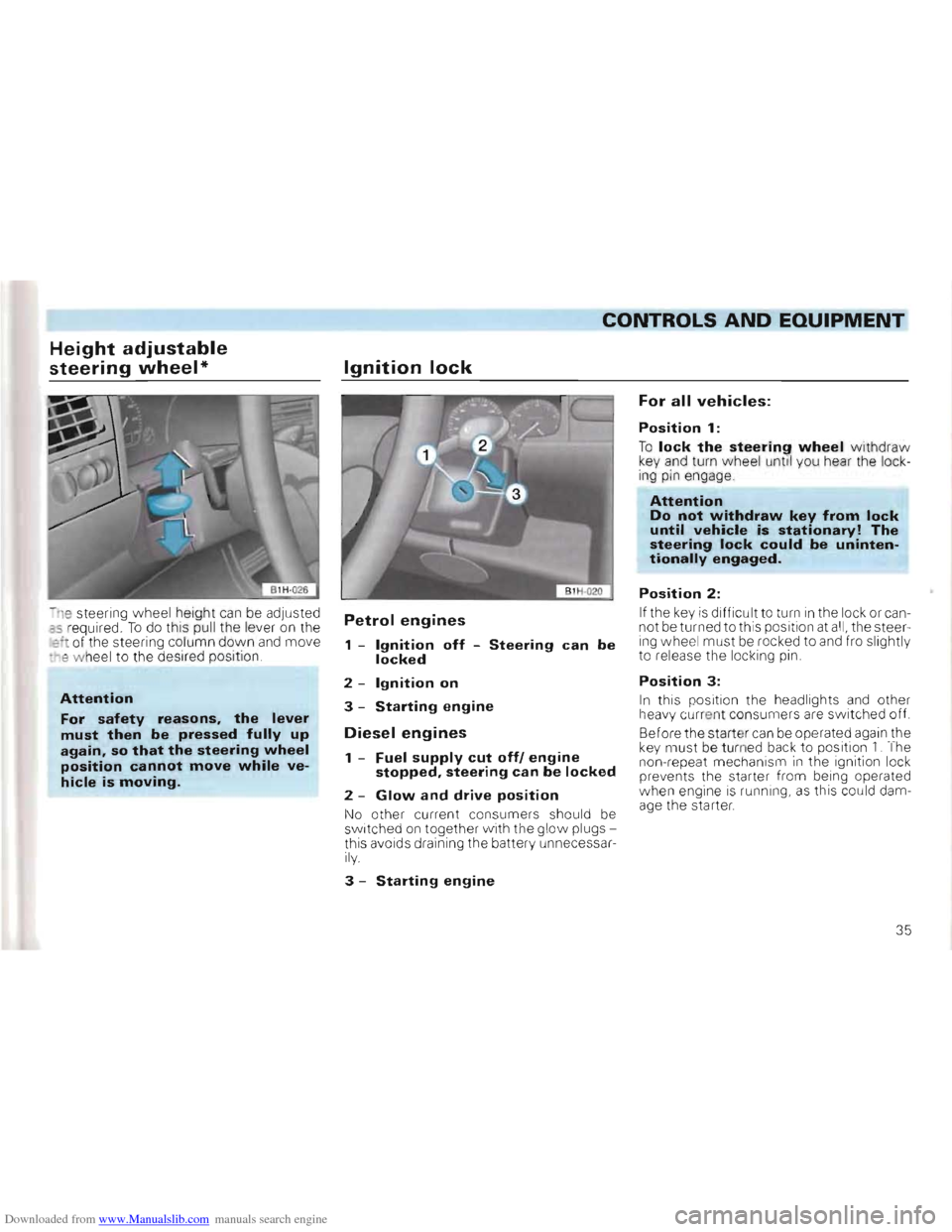
-n e steering wheel height can be adjusted as r equired . To do this pull the lever on the :::1 of th e stee ring co lumn down and move -~e w hee l to the desir ed position
Attention
For safety reasons, the lever
must then be pressed fully up again, so that the steering wheel position cannot move while ve
hicle is moving.
Ignition lock
Petrol engines
1 -Ignition off -Steering can be locked
2 -Ignition on
3 -Starting engine
Diesel engines
1 -Fuel supply cut off! engine stopped, steering can be locked
2 -Glow and drive position
No other current co nsumer s should be sw itc hed on together w ith the glow plugs
this aVOi d s dra ining the batte ry unn ecessa rily.
3 -Starting engine
For all vehicles:
Position 1:
To lock the steering wheel withdraw key and turn wheel unti l you hear the lock
ing pin engage
Attention Do not withdraw key from lock until vehicle is stationary! The steering lock could be unintentionally engaged.
Position 2:
If the key is difficult to turn in the lock or can
not be turned to this position at all, the steer
ing wheel must be rocked to and fro slightly
to release the locking pin .
Position 3:
In this pos ition the headlights and other
h eavy cu rre nt consume rs are switched off.
Before the start er
can be operated again the key must be turned back to position 1. The
non-repeat mechanism in the ignition lock
prevents th e starter from being operated
w hen engine
is ru nning, as this could dam
age the starter.
35
Page 39 of 156
Downloaded from www.Manualslib.com manuals search engine ___CONTROLS AND EQUIPMENT
Diesel engines
Glow plug system
Ith the 47 and 66 kW Diesel engines. ~fter sw itching to the driving position (ignion on ), the required glow plug warm-up
• m e is Indicated by a lamp which is con
:r oll ed by the coolant temperature -see
p ag e 47 .
On he
55 kW Diesel engine the glow pl ug sys tem is automaticall y activated after ~'osing the driver's door. If the engine is not subsequentl y sta rted, the glow plug syst em .111 not be activated by each further opening an closing of the driver's door.
Cold starting aid/idling speed
boost (47 and 55 kW engines only)
-0 facilitate starting from cold, there is a
c old starting device (cold sta rting aid) in the nJec tion pump.
he cold starting device is actuated when "'1e knob on h e left of the steerinq column
s pulle d out fully.
fl addition , the idling speed can be in~reased with the knob to reduce any vehicle
• br ation which may occur .
47 and 55 kW engines
Starting a cold engine
• At ambient temperatures down to -155C, pull the cold start knob out fully before operating the sta rter .
At lower t em pe rature s, the knob should not
be pulle d out until engine is firing regularly -the engine wi ll then start more
readily .
•
Turn the key in the igniti on lock to posi
tion 2 (see page 35) -the glow plug wa rning
lamp comes on. It goes out when the igni
t ion tempera ture is reached (see page 47) While the glow plugs are working do not switch on any other heavy current consumers because this would place an unnecessary load on the battery.
• When the w arning lam p goes out, start
the engine immediatel y
D o not depress the acce lerator while star
ting
If the
engine only fire s irregul arly, continue to ope rate the starter a few seconds longer (30 seconds at maximum) until the engine
runs under its own power. If
the eng ine does not start , switch the g
low plugs on again and try starting it again as de
scr ibed . If th e eng ine still doe s not start the
fuse for the glow plugs may have blown
page 120 .
• Push the cold start aid knob
in fully as soon as the engin e has rea ched its norma l
operating te mper ature.
If ve hicle vibrati on then
occurs whe n i dling,
the knob can be pul led out again until the en
gine runs free of vibration at the lowest
pos sible idling speed
Starting a warm engine
The glow plug lamp does not come on -the engin e can be started straight away. D o not pull the cold s tart aid knob and do not press
the accelerator pedal.
37