lock VOLKSWAGEN GOLF 1993 1H / 3.G Service Manual
[x] Cancel search | Manufacturer: VOLKSWAGEN, Model Year: 1993, Model line: GOLF, Model: VOLKSWAGEN GOLF 1993 1H / 3.GPages: 156, PDF Size: 6.36 MB
Page 92 of 156
Downloaded from www.Manualslib.com manuals search engine GENERAL MAINTENANCE
Bonnet
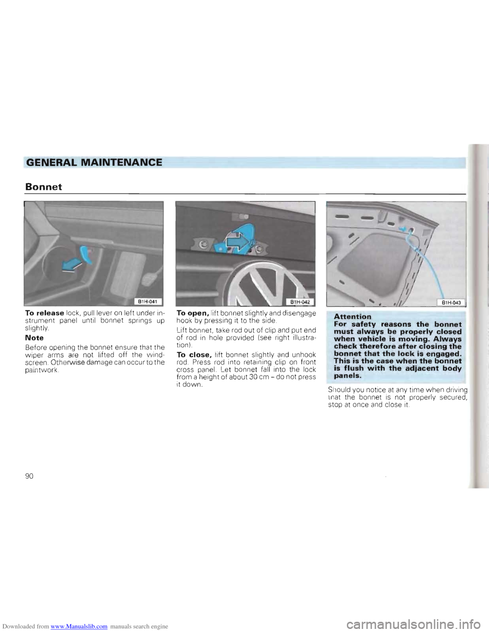
To release lock, pull lever on left under in
strument panel until bonnet springs up slightly.
Note
Before opening the bo nnet ensure that the
wiper arms are not lifted off the wind
screen. Othe rwise damage can occur to the
palntwork. To
open, lift
bonnet slightly and disengage
hook by pressing it to the side.
Lift bonnet, take rod out of
clip
and put end
of rod in hole provided (see right illustra
tion)
To
close, lift bonnet slightly and unhoo k
rod. Press rod into retaining cl ip on front
cross panel. Let bonnet fall into the lock
from a height of about 30 cm -do not press
it down.
B1H -043
Attention For safety reasons the bonnet must always be properly closed when vehicle is moving. Always check therefore after closing the bonnet that the lock is engaged. This is the case when the bonnet is flush with the adiacent body panels.
Should you notice at any time when driving
that the bonnet is not properly secured,
stop at once and close it.
90
Page 118 of 156
Downloaded from www.Manualslib.com manuals search engine DO-lT-YOURSELF
Changing wheels
Park the vehicle as far as possible away
from the traffic flow. If necessary switch on
emergency warning lights
and place the
warning triangle in position -note legal reQuirements,
• A
ll veh icles occupa nts shou ld leave the
vehicle and move to a safe area (e,g, behind
the barrier),
• App ly handbrake firml
y, If the car is on a
slope, block one of the wheels on the oppo
site side with a stone or some similar ob
ject.
•
Take too ls and spare wheel out of lug
gage compartment.
• Remove wheel bolt caps:
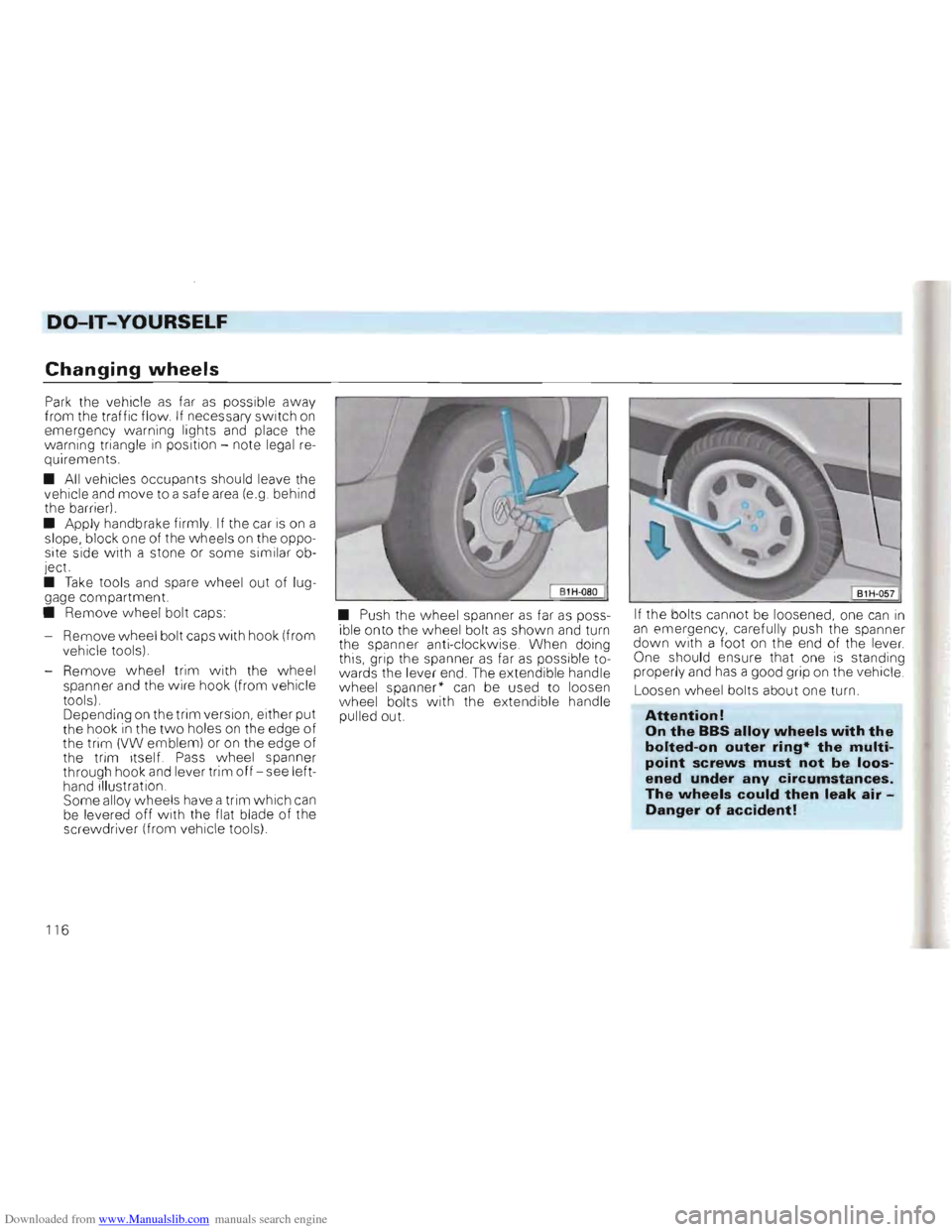
- Remove wheel bolt caps
with hook (from
vehicle tools),
- Remove wheel trim with the
wheel
spanner and the wire hook (from vehicle
tools) ,
Depending
on the trim version , either put
the hook in the two holes on the edge of the trim (VW emblem) or on the edge of
the trim itself, Pass wheel spanner
through hook and lever trim off -see left
hand illustration ,
Some alloy wheels have a trim which can be levered off with the flat blade of the
screwdriver (from vehicle tools) •
Push the wheel spanner
as far as poss
ible onto the wheel bolt as shown and turn
the spanner anti-clockwise, When doing
this, grip the spanner
as far as possib le to
wards the lever end, The extend ib le handle
wheel spanner"
can be used to loosen wheel bolts with the extendible handle
pulled out. If
the bolts cannot be loosened, one can
in an emergency, carefully push the spanner down wi th a foot on the end of the lever.
One should ensure that one is standing
proper ly and has a good grip on the vehic le ,
Loosen
wheel bolts about one turn,
Attention!
On the BBS alloy wheels with the
bolted-on outer ring· the multi
point screws must not be loos
ened under any circumstances.
The wheels could then leak air Danger of accident!
116
Page 122 of 156
Downloaded from www.Manualslib.com manuals search engine DO-lT-YOURSELF
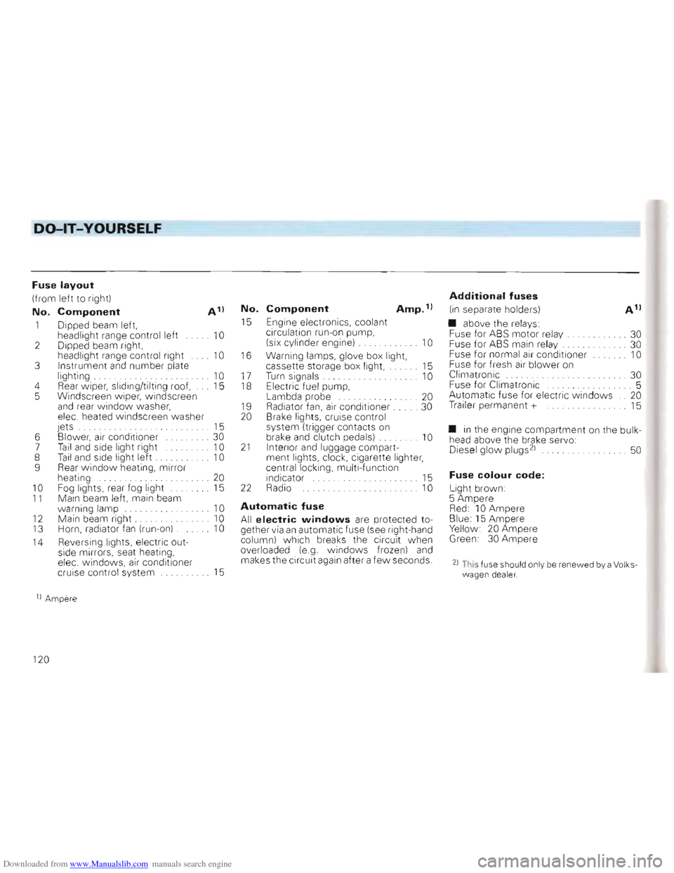
Fuse layout
(from left to rig ht)
No. Component A 1)
1 Dipped beam left,
headlight range control left 10 2 Dipped beam right,
head light ra nge co ntrol right 10 3 Instrument and number plate
light ing . 10 4 Rear w iper, slid ing/tilti ng roo f, 15
5 Windscreen w ipe r, windscr een
a
nd rea r w indo w was her,
ele c. heated windsc reen washer
jets . . . . . . 15
6 Blower,
air co nditi oner ... . 30
7 Tail and side light ri ght 10
8 Tail and side light left . . 10
9 Rear window heating , mirror
heating ... 20 10 F og lights, rear fog light 15 11 Main beam left, main beam
w arnin g lamp 10
12 Mai n bea m right . 10
13 Horn, radiator fan (run- on) . 10
14 Reve
rsi ng lights, electric out
side mirrors, seat heating,
elec. w ind ows,
air conditio ne r
cruis e contro l system 15
No. Component Amp. 1)
15 Engine elec tronics , cool ant
c irculat ion run- on pump,
(six cylinder engine)
.. . .. .. . . . 10
16
Warning lamps, glove box light,
cas sette sto rage box light, 15
17 T urn sig nals. . . . . . . . . . . . .. 10 18 Electri c fue l pum p,
Lambda probe ..... .. ....... 20
1 9 Radiat or fan, air cond itioner. . 30
20 Brake lights, cruise control
syste m (tri gger conta cts
on brake and clutch pedals) . 10 21 Interior and luggage compart
ment lights, clock, cigarette lighter,
ce ntral
locking, multi -function
indicator 15 22 Radio 10
Automatic fuse
All electric windows are protected to
ge ther via an automatic fu se (see rig ht -hand
co lum n) which breaks the circuit when
overloaded (e .g. windows frozen) and makes the circuit again after a few seconds.
Additional fuses
(in separate holders)
• above the
rela ys:
Fu se for ABS motor re lay. ..... . .... 30
Fuse for ABS main relay. ... 30
Fuse for normal air conditioner 10
Fuse for fresh air blower on
Climatronic ... ... ... . 30
Fuse for C1imatronic .. .... ... 5
Automatic fuse for electric w indo ws .. 20
Trailer perma nent + 15
• in the engin e compa rtment on the bulk
head above the brake servo:
Diesel glow plugs 21 . . 50
Fuse colour code:
Light brown :
5 Amper e
Red: 10 Ampere Blue: 15 Ampere Yellow 20 Ampere Green 30 Ampere
21 This fuse shou ld onl y be renewed by a Volks wagen dea ler.
1) Amper e
120
Page 130 of 156
Downloaded from www.Manualslib.com manuals search engine ----DO-lT-YOURSELF
Emergency starting
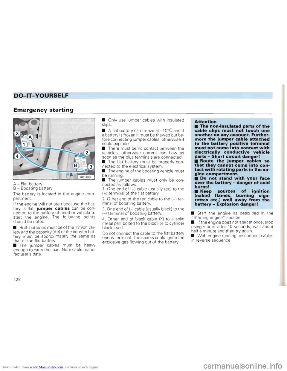
A -Flat battery
B - Boosting battery
The battery
is located in the engine com
partment.
I f the engine will not start because the bat
tery is flat.
jumper cables can be con
nected to the battery of another vehicle to
start the engine . The follow ing points
should be noted
• Both batteries
must be of the 12 Volt var
iety and the capacity (Ah) of the booster bat
tery must be app roximately the same as that of the flat battery .
• The jumper cables must be heavy
enough to carry the load. Note cable manu
facture r's data. •
Only use Jumper cabl
es with insulated
clips.
• A flat battery
can freeze at -1 Ooe and if
a battery is frozen it must be thawed out be
fore connecting Jumper cables, o th erwise it
could explode.
• There
must be no contact between the
vehic les, other wise current can flo w as soon as the plus terminal s are connected .
• The flat battery
must be properly con
nected to the electrical system.
• The engine of the boosting vehicle
must be running.
•
The jumper cables must only be con
nected as follo w s: 1. One end of (+) cable (usually red) to the (+) term inal of the flat battery.
2 . Other end of the red cable to the (+l ter
minal
of boosting battery.
3. One end of H cable (usually black) to the
H terminal of boosting battery.
4. Other end of blac k cable (X) to a solid
metal part bolted to th e block or to cylinder
block itself.
Do not connect the cable to the flat battery
m in us terminal. The sparks could Ignite the
exp losive gas flowing out of the battery
Attention • The non-insulated parts of the cable clips must not touch one another on any account. Furthermore the jumper cable attached to the battery positive terminal must not come into contact with electrically conductive vehicle parts -Short circuit danger! • Route the jumper cables so that they cannot come into contact with rotating parts in the engine compartment. • Do not stand with your face over the battery -danger of acid burns! • Keep sources of igni~ion(naked flames, burning cIgarettes etc.) well away from the battery -Explosion danger!
• Start the engine as described in the
"Starting engine" section.
• If the engine does not start at once, stop
using starter after
10 seconds, wait about
half a minute and then try aga in.
• With engine running, disconnect cables in reverse sequence .
1 28
Page 149 of 156
Downloaded from www.Manualslib.com manuals search engine TECHNICAL DATA
Vehicle identification data
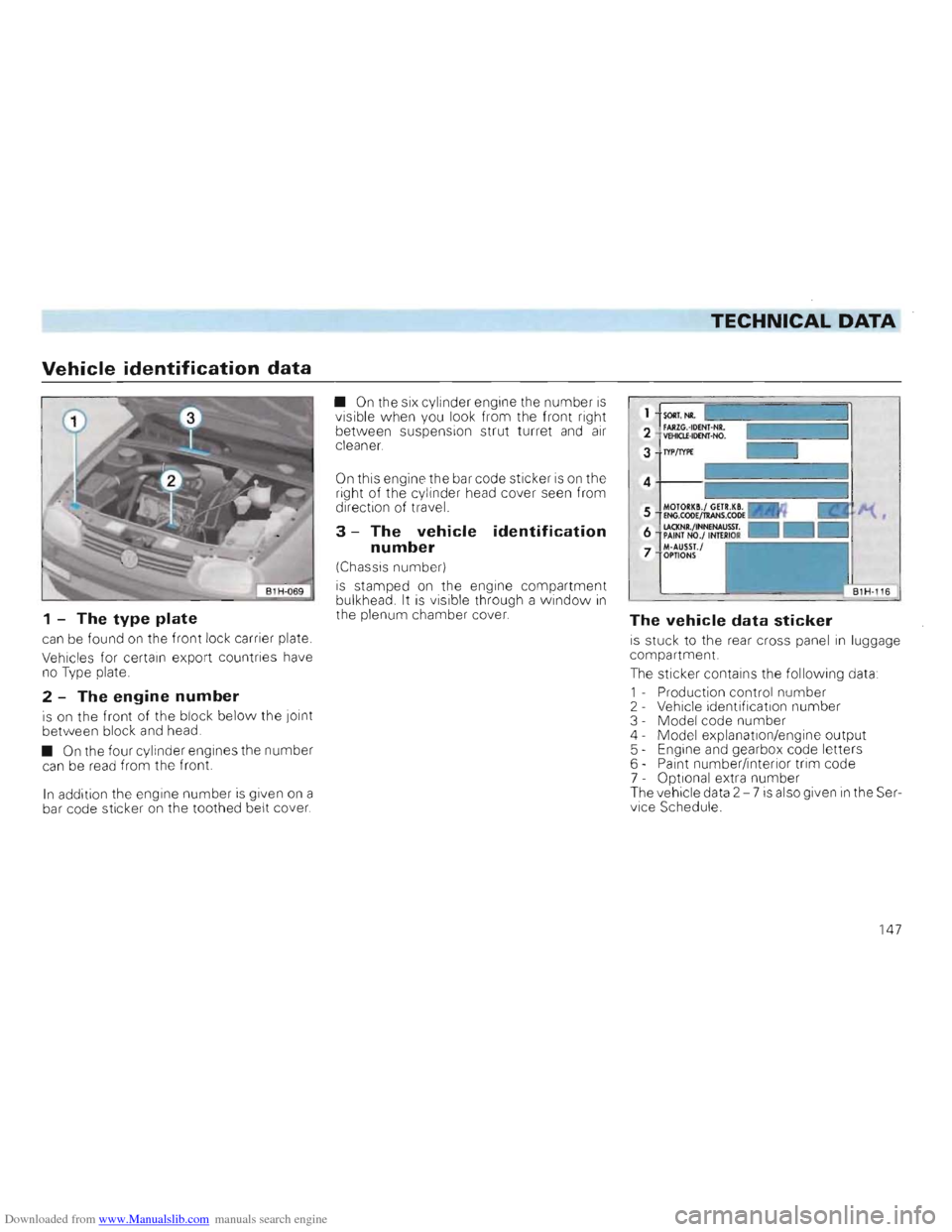
1 -The type plate
can be found on the front lock carrier plate.
Vehicles for certain export countries have
no Type plate.
2 -The engine number
is on the front of the block below the joint
between block and head.
•
On the four cylinder engines the numbe r can be read from the front.
In addition the engine number is given on a
bar code sticker on the toothed belt cover. •
On the six
cyl inder engine the number is visible when you look from the front right
between suspension strut turret and air cleaner.
On this engine the bar code sticker is on the
right of the cy linder head cover seen from
direction of travel.
3 -The vehicle identification
number
(Chassis number)
is stamped on the engine compartment
bulkhead. It is visible through a window in
the plenum chamber cover. The vehicle data sticker
is stuck to the rear cross panel in luggage
compartment.
The sticker contains the follow i
ng data:
1 - Production control nu mber
2 - Vehicle identification number
3 - Mode l code number
4 - Model explanation/engine output
5 - Engine
and gearbox code letters
6 - Paint number/interior trim code
7 - Optional extra number
The vehicle data 2 -7
is also given in the Ser
vice Schedule .
147
Page 150 of 156
Downloaded from www.Manualslib.com manuals search engine ALPHABETICAL INDEX
A Acceleration figu res . . .... . . .
Accessories
Adjusting washer jets
A ir conditioner
.. ....... .
Airbag
Alloy w heels
Analog clock
..
Anti-freeze.
Anti-dazzle inside mirror
Anti-knock properties of the fuel
Anti-locking brake system
(ABS)
Anti-theft warning system
Aq uaplaning .... ..... .
Ashtray .......... . .
ATF.
Automatic gearbox.
Automatic tra ns mission fluid
Automati c was h plants .... . . . .
Axle weights. . ....... .
B Battery . . . ....... . . . . .
Belt height adjustment ... .. . . .
Blower ...
Bonnet.
B rake fluid.
Brake pad wear indicat or
Brake servo .
Brake system
Brake warni
ng I'amp .
B rakes
B ulb changing.
Burglar alarm .
1
36
111
103
59
18
88
41
97
12
82
76
8
106
68
96
32
96
85
143
100
15
56, 59
90
99
48
75
99
48
75
121
8
C Capacities .. . . .... . 146
Care 85
Care of body . . . . . . . . . . . . . 85
Care of vehicle 85
Cavity preservation 89
Central locking system 7
Cetane Number . . . . . . . . . . 84
Changing bulb s . . . . . . . . . . 1
21
Changing wheels 116
Chassis number 147
Child safety . 21
Child seats ........ . . . . . . . 21
Chi ld-proo f catch ......... 9
Cigarette lig hter 68
Cigarette lig h ter socket. 68
Cleaning and anti -corrosion treatment of
engine compartment . . . . . . . . 88
Clean ing veh ic le . . . . . . . . . . 85
C limat ronic 62
Clock .. 41
Cockpit . . . . . . . . . . 4
Cold starting aid 37
Compression rat io 134
Cons umption figures. . 137
Coolant additive 97
Coolant level 46, 97
Coolant tempera ture gauge 45
Cool ing system . . . . . . . . . . 97
Cruise control system 54
Cubic capacity 134
D Dash panel 4
Defrosting windows 57,60,62
Diesel fuel 84
Dimensions. 145
Dip lever 53
Direction indicators 48, 53
Do-it-yourself ......... .
112
Door locks . ..... . . 9
Doors . .. 9
Driver's seat
25
Driving abroad .... . 110
Driving economically 72
Driving tips ...... . ... ..... ..... . 71
Driving with four-wheel drive 79
Dust and pollen filter ...... . .. . . 104
1 48
Page 151 of 156
Downloaded from www.Manualslib.com manuals search engine ALPHABETICAL INDEX
E F H Electri
c windows 10.52 Fan . . .. 98 Hand brake 31 Emergency li ght s 51 Filling the tank ...... . . 81 Head restraints .. ............... 24
E me rgency startin g 128
Filter preheating .......... . . 84 Headlight flasher ........ .. . 53 Engine First
aid kit ........... . . . 112 Headlight range control ........... 51 -Code letters 147
Folding/sliding cover 30 Headlig ht washer system
55
- Data 134 Foot mats ............ . 31 Heated rear window 52 -Number 147 Four wheel drive 79 Heating
56 -Oil .. 92 Fresh air filte r ........ . 104 Height adjustable seat. 26
- Oil capacity. 146 Fresh air venti lation
58, 61 Height adjustable steering wheel
35
- Oil change intervals 2.95 Front fogligh ts ........... . .
50 High beams. ........... 48
- Oil consumption
94 Front
seats
25 Horn
4
- Oil level
..... . . .. . . 94 Fuel ........... . . . 82
- Oil pressure 47 -Additives. 83, 84
- Starting/stopping 36 -
Consumption ........ . 72,137 Engine compartment. 91 -Filter preh eating . 84 Identification
data
147
E ngine number. 147 -Gauge
45 Idling speed boost ......... 37 ~Environment -Saving
72 Ignition lock. . . . . . . . . 35
-Battery. . . . . . . . . . . . .
. . . . . . . .. 102 Fuel gauge Fuses. 45
119 Increasing
luggage space
I nertia reel belts ......... 27 14 -Brake fluid. . . . . . . . . . . . . . . . . . .. 99 InSide mirror . . . . . . . . . . . . 12 -Care ofcar. . . . . . . . . . . . . . . . . . .. -Coolant ...................... 85 98 G Inspection intervals
Instruments 95
39
-Driving with low emissions and n
oise......... ............... 72 Gear change marks
Gear stick ....... . . 39, 71 31 Interior
lights 67
-Engine oil .................... -En vironmentally conscious drivin g . . . . . . . . . . . . . . . . . . . . . .. - Exhaust gas system .... . .. . ...
95
72
74
Glove box light .......... .
Glow plugs
Gross vehicle
weight
67,126 37
143
- Filling th e tank ................ 81 -~~.......................... ~ -Maintenance. . . . . . . . . . . . . . . . . .. 2 - Old oil . ....................... 95 - Old tyres .................... 107 - Tyre pressure ................ 105 - Tvres .... . .. . . ............... 107 - Unfeade d fuel. . . . . . . . . . . . . . . .. 83 - Washing th e vehicle ........... 86 Exha..JS. gas system 74
149
Page 152 of 156
Downloaded from www.Manualslib.com manuals search engine ALPHABETICAL INDEX
J Jack 11 4, 117 Jack sockets . 117
Jumper cable 128
K Keys. 6 Kick-down
33
L Lap belt 16
Leather care ....... .
87
L ifting vehicle . . .......... .
13 1
Lighting ....... .
50
Lighting sw itch .
50
Locks . .
... 9 Lubricant add iti ves .
96
Lubricants .
92
Luggage boot
light
.. 67, 126
Luggage compartment 28
Luggage compartment cover . 30
Luggage compartment light 67, 126
Lumbar support 26
M M + S tyres 109,
139
Maintenance .. 2 M ake-up mirror . . 66 M anual gearbo x 31 Masking headlights 110 Max
imu m speed ..... .. .. . 136 Mesh partition 29
Mileage recorder 39
Mirror heating
..... ... . . . 12
Mirrors . 12
Mobile
telephones. ... . . .. .. 111 Modifications 111 Multi function indicator ......... .
42
150
N Number plate lighting
125
o Octane number .. ... .. . .
82
Oil capacity ...... .. . .
146 011 change intervals
95
Oil change intervals 2 Oil consumption .
94
Oil dipstick
- Automatic gearbox
..... ... . 96 -Engine . . .. ..... . 94 Oil pressure ......... .
47
O il spec ifications
92
O il
s. . .. .... . .
92 Output. . ... . . . .... .. .... .
134
Outside mirrors
12
P Paint care ..... . . .
86
Paint number 147
Par
king. 74 Par . ing lights 53 Par ing lock .. . 32
Pedals 31 Performance .... . ... .... ........ . 136
Petro l,
- Quality .
82
Petrol additives . .
...... .
. 83
Pollen filter . . . . 104
Power assisted steering 96
R Radio ..... 127
Reading light . . . . . . . . . . . . . . . . . . . . 67
Rear foglight . . . . . . . . . . . 50
Rear lights. . . . . . . . . . . . . . . . . . 1 25
Rear seat . 27
Rear
window w ash/wipe 55 Releas ing tank flap . 82
Renewa l of parts ........ .. . ... 111 Restraint systems 13, 21
Rev counter . .... ...... 41 Reverse gear . . . . . . . . . . 32 Reversing lights . . .. 3 1
Roof load . . . . . . . . . . . . .. 70 , 143
Roof load carrying system 70
Roof rack . 70
Roof
ra i ling 70
Running in . . . . . . . . . . . . . . . .. 71