trailer VOLKSWAGEN GOLF 1993 1H / 3.G Owners Manual
[x] Cancel search | Manufacturer: VOLKSWAGEN, Model Year: 1993, Model line: GOLF, Model: VOLKSWAGEN GOLF 1993 1H / 3.GPages: 156, PDF Size: 6.36 MB
Page 5 of 156
Downloaded from www.Manualslib.com manuals search engine CONTROLS AND EQUIPMENT
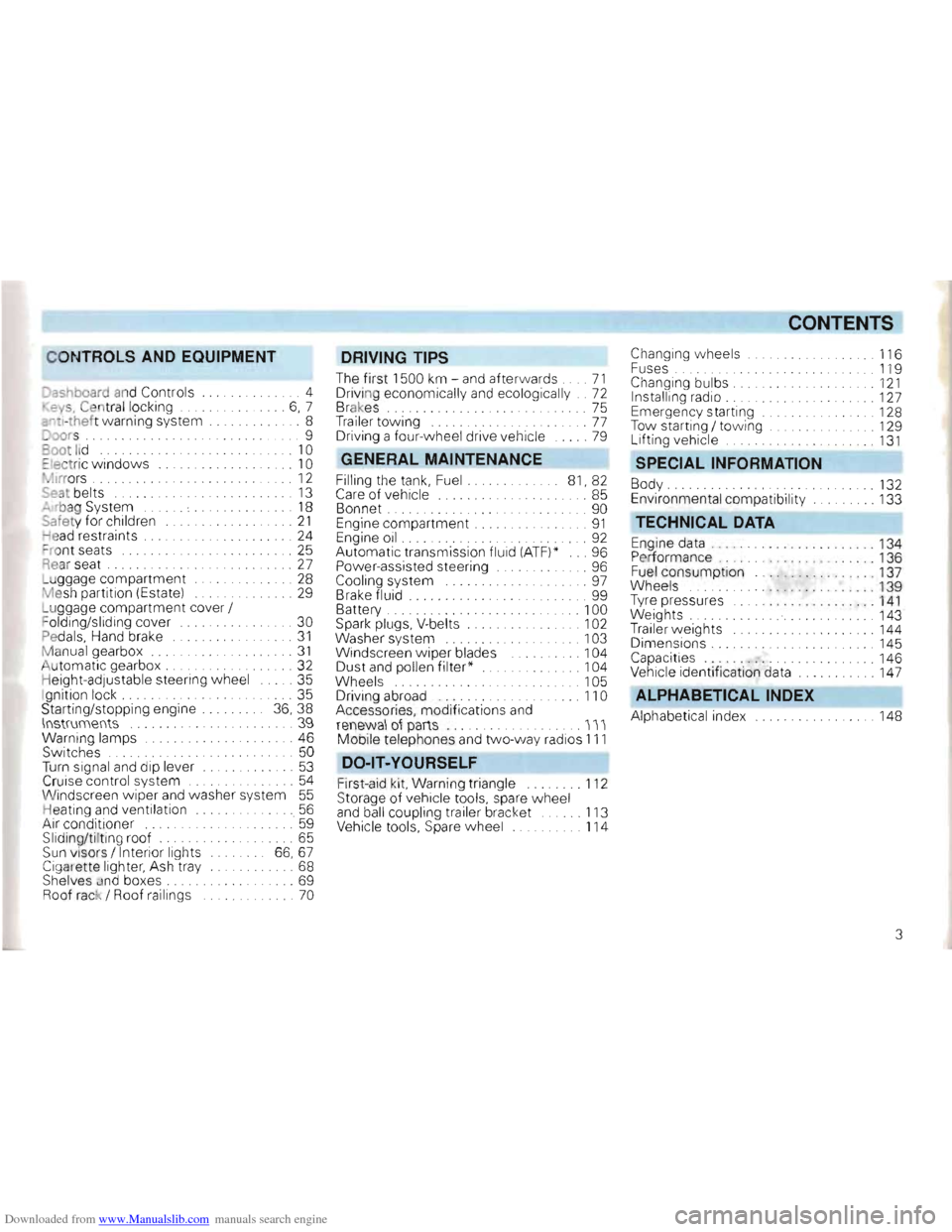
Dashboard and Controls ..... 4
. ey s, Cen tral locking . . .... 6, 7
::"tl-thef t warning system .... 8
Joors .......................... .... 9
oot lid .... ........... . . . . . 10
::Iectric windows .. . .. 10
• ~Irrors . . ..... . ... 12
Seal belts 13
"" rbag System . . . . . 18
Safe ty for children .. ... 21
ead restraints . . . . . .. 24
= ro nt seats . . . . . . . . . . . .. 25
Rear seat . . . 27
L u ggage compartment ... . ... . ...... 28
M esh partition (Estate) ...... 29
L u ggage compartment cover /
F olding/sliding cover
... 30
Pedals, Hand brake .. 31
Manual gearbox .... ... .... 31
Automati c gearbox . . . .. .......... 32
H eig ht-adjustable steering wheel ..... 35
I gnition lock. . . . . .. 35
Starting/stopp ing engine 36, 38
\lIstrumellts .. .... 39
Warning lamps ....... 46
Switches . . . . . . . . . . . . . . 50
Turn signal and dip lever ............. 53
Cruise control system ........... 54
Wi ndscreen wipe r and washer system 55
Heating an d ventilation .. . ...... 56
Air cond itioner ......' 59
Sliding/ti ltin g roof. . . . . . . . . . . . ... 65
Sun visors / Interior lights 66,67
Cigarette lighter, Ash tray ..... 68
Shelves and boxes . . . . . . . . . . . ... 69
Roof rack / Roof ra ilings ... 70
DRIVING TIPS
The firs t 1500 km -and after wards .... 71
Driving economically and ecologically .. 72
Brakes. . . . . . . . . . . . . . . . 75
Tra iler tow ing . .. ..... . .... ... ...... 77
Driving a four- wheel drive vehicle .. 79
GENERAL MAINTENANCE
Filling the tan k, Fuel. 81, 82
Care of vehicle ........ .. . . 85
Bonnet . . ... 90
Engine compartment .. ...... .... .... 91
Engine oil ..... .......... ........... 92
Automatic transmission fluid (ATF)* ... 96
Power-assisted steering .. 96
Cooling system . . . . . . . . . . .. . 97
B rake fluid ...... 99
Battery . . . . .. 100
Spark plugs. V-belts . . . . . . . . . 102
Washer system
... . .. 103
Windscreen w iper blades . . . 104
Dust a
nd pollen filter * . 104
Wheel s . 105
D riving abroad ..... ............... 110
Accessories, modifications and
renewa l ot parts .............. III
Mobile telephones and tw o-way rad ios 111
DO -lT-YOURSELF
First -aid kit, Warn ing triangle ........ 112
Storage of vehicle tools, spare wheel
a n d ball coupling trailer bracket ...... 113
Vehicle tools, Spare wheel 114
CONTENTS
Changing w heels . 116
F uses . ........ .. .. . . . ... . .... 119
Changing bulbs. . .... .. . 121
Installing radio . . . . .. 127
E mergency starting .. .. 128
Tow starting / to wing . . .. 129
L ift ing vehicle ......... 131
SPECIAL INFORMATION
Body ..... .... . .......... 132
Environmental compatibility ... 133
TECHNICAL DATA
Engine data . .. , .... .... . 134
P er forman ce .. ... ... ... . .. 136
Fuel consump tion .. 137
Wh eels
. . 139
T yre pressures
.. .. ... .. . . .. ... 1 4 1
Weights ... 143
Trailer weights .. 144
Dimensions. ...... .. ... 145
Capacities " ..... 146
Vehicle identification data ... 147
ALPHABETICAL INDEX
Alph abetical index ... 148
3
Page 50 of 156
Downloaded from www.Manualslib.com manuals search engine CONTROLS AND EQUIPMENT
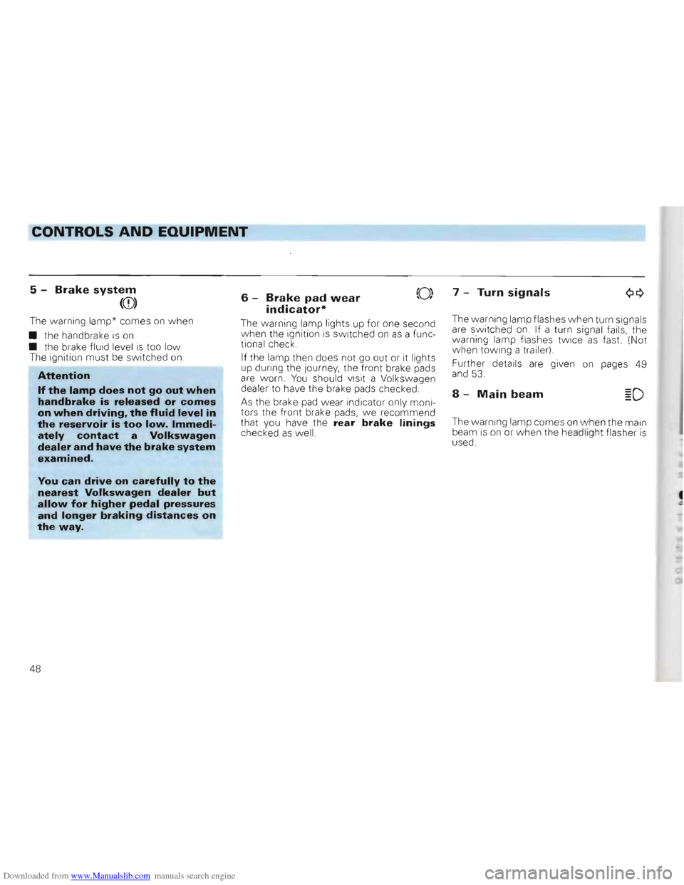
5 -Brake system
(CD)
The warning lamp* co mes on when
• the handb rake is
on • the brake fluid level is too low The ignition must be switched on.
Attention
If the lamp does not go out when handbrake is released or comes on when driving, the fluid level in the reservoir is too low. Immedi
ately contact a Volkswagen dealer and have the brake system
examined.
You can drive on carefully to the
nearest Volkswagen dealer but allow for higher pedal pressures and longer braking distances on
the way.
I6 -Brake pad wear I,'0',
indicator*
The wa rning lamp lights up for one second when the ignition is switched on as a func
tiona l check.
If the lamp then does not go out or it lights
up dur ing the Journey , the front brake pads
are worn. You should visit a Volkswagen
dealer to have the brake pads checked.
As the brake pad wea r indicator only moni
t ors the front brake pads, we recommend
that you have the rear brake linings checked as well.
7 -Turn signals
The warn ing lamp flashe s when turn signals are sWitched on. If a turn signal fails, the
warning lamp flashes tw ice as fast. (Not
w hen towing a trailer )
Fur ther details are given
on pages 49 and 53.
8 -Main beam
The warning lamp come s on when th e main
beam is on or when the headligh t flas her is used.
48
Page 51 of 156
Downloaded from www.Manualslib.com manuals search engine ----CONTROLS AND EQUIPMENT
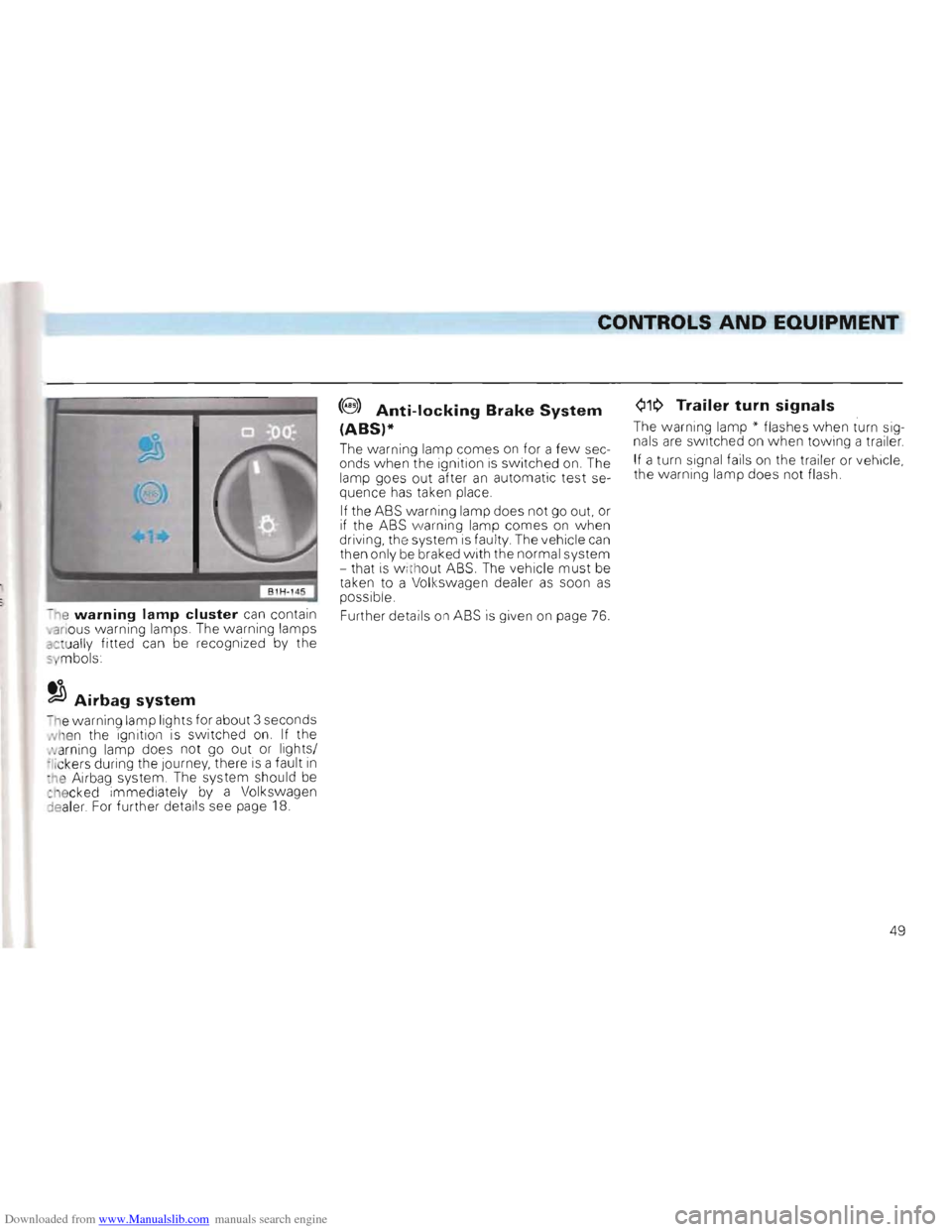
Q1~ Trailer turn signals(8 ) Anti-locking Brake System
(ABS)* The warning lamp" flashes when turn sig
nals are switched on when towing a trailer. The warning lamp comes on for a few sec
onds when the ignition is switched on. The If a turn signal fai ls on the trailer or vehicle,
lamp goes out after
an automatic test se the
warning lamp does not flash.
quence has taken place,
If the ASS warning lamp does not go out. or if the ASS warning lamp comes on when
driving, the system is fau lty The vehicle can then only be braked with the normal system
- that is w ith out ASS. The vehicle must be taken to a Vol kswagen dealer as soon as possible .
- ne
warning lamp cluster can contain Further details on ASS is given on page 76 . •anous warning lamps. The warning lamps actually fitted can be recognized by the 5 mbols
to ~Airbag system
n e warning lamp lights for about 3 seconds Nhen the ignition is switched on. If the
N arning lamp does not go out or lights/
;Iickers during the Journey, there is a fault in :he Airbag system , The system should be ct16cked immediately by a Volkswagen
:lealer For further details see page 18.
49
Page 73 of 156
Downloaded from www.Manualslib.com manuals search engine DRIVING TIPS
The first 1500 km -and afterwards
Running-in
D Uring the first few opera ting hours the engine interna l friction is hig her than later on
w hen all the moving parts have b edded
d own . How well this running-in process is
d one depe nds to a considerab le exten t on th e w ay the vehicle is dri ven during the first
1 500 km (1000 miles)
Up to 1000 kilometers
the follo win g general rules apply :
• Do not use full throttle • Do not drive faster than 3/4 of top speed • Avoid high engine speeds
• Trailer towing should if possib le be
avoided .
Attention • New tyres must also be .. run in" because they do not have maximum adhesion at the start. This must be taken into account by driving carefully during the first 100 km_ •
•
New brake linings must also be run in and do not have the optimum friction properties during the first 200 km. The slightly reduced braking effect can be compensated for by more pressure on the brake pedal. This also applies when new linings have been fitted.
From 1000 -1500 km
The speed can gradu ally be increased to the
road or eng in e maximum.
During and after the running-in
period the following applies:
• Do not overre v th e engine when cold
eithe r in neutra l or in th e gears .
All speeds and revs given are only valid
w hen engine is properly warm.
r:Gb Do not drive with the engine C!!t) speed unnecessarily high changing up early helps to save fuel, reduces noise and protects the environment -see also page 72.
• Do not let engine labour -ch ange down
when eng ine no lo nger runs s m oothly .
After the running-in period
• On v ehic les with a rev counter* th e maxim um perm issib le e ngine speed is shown by the begin ning of the red zone on
the rev counter scale. The needle of the
c o unter must not mov e into this zone.
E xtreme ly
hig h engine revs w ill be auto
matically go verned.
71
Page 74 of 156
Downloaded from www.Manualslib.com manuals search engine DRIVING TIPS
Driving economically and ecologically
Various factors de te rmi ne the fuel c on
sumption, the bur de n on the environment
a n d the w ear on the engi ne, brake s an d
t y res .
The personal style of driving
Determine s to a g reat extent th e eco nomical asp ect and the e xha u st an d no ise deve lo pmen t:
r:Q,., Do not warm up the engine with '(!t!5 the vehicle stationary.
At idling speed it takes a very long time until the engine becomes operationally warm. However, in the warm-up phase, wear and the discharge of pollutants is particularly high. For this reason, drive off immediately the engine has started and avoid high engine speeds.
QiP Avoid full throttle acceleration.
N'6t only is the fuel consumption reduced considerably if one accelerates with feel
ing, but the disturbance to the environment and the wear are also reduced.
r:Q,., Do not drive with unnecessarily '(!t!5 high engine revs -change up as soon as possible, only change down when the engine no longer runs smoothly.
The fuel consumption is for example more than twice as high in 2nd gear than it is in top gear. At the same time, the reduced engine speed means a reduction in engine noise.
r:Q,., Try not to drive at m aximum '(!t!5 speed.
The fuel consumption, exhaust pollution and noise increase disproportionately at high speeds. If approximately only 3 quarters of top speed is utilised, the fuel consumption will be reduced by about half. Experience has shown that the loss
in time is only marginal.
r:Q,., Drive as smoothly as possible '(!t!5 and look well ahead.
Unnecessary acc eleration and braking must be paid for with higher fuel consumption and more disturbance to the environment.
r:Q,., Switch the engine off during '(!t!5 traffic hold-Ups.
The individual operating condi
tions
N atur ally also affect fuel cons umption .
T he fo
llowing facto rs fo r in sta n ce are not fa
vo urable to good fuel c on sumption:
• Hig h traff ic de ns it y , par ticularly larg e
t o w ns w ith numero us traffi c lig ht s
• Freq ue nt sto p/s tart d
riving, alw ay s re
s ta rti ng a nd warmin g up t he eng ine
• D riving
in heavy , slow moving traff ic in
l o w gear so that the eng ine sp eed is rela
ti vel y high in relati on to the distan ce cov
e red.
r:Q,., One should, therefore, p la n trips
'(!t!5 in advance and try to a void l ocal
traffic and overcrowded motor
ways.
O bvio usly the fuel consumption is also af
fec ted by facto rs o ve r w hich the drive r has
n o control. It is for exampl e no rma l for th e con sumpti o n t o increase in th e ,,\linte r or in arduous cond iti ons ( bad roads, trailer towing etc)
72
Page 79 of 156
Downloaded from www.Manualslib.com manuals search engine DRIVING TIPS
Trailer towing
The vehicle is intended main ly for the trans
portation of persons and luggage but it can, with the appropriate technical equipment,
also be used to tow a trailer.
Technical requirements
• If the vehicle is suppl ied with a factoryfi tted towing bracket, all that is technically
a nd legally necessary for trailer towing wil l
have been taken into account.
• If the trailer to be towed
has a 7 pin plug, an adapte r cable can be used whi ch IS ob
tained from a Volkswagen dealer.
• Volkswagen dealers have
all the necessary information on the In stallation of towing
brackets and the fitti ng of a heavy-duty cooling system. The installation should there
f ore be done by them .
Operations instructions
• On the Golf saloon with a factory
fitted towing bracket* the removable ball
coupling will
be fitted. Fitting/remo ving in
struc tions and instructions on correct stowage of the ball coupling in the spare wheel
well can be found in a linen bag in the ve
hicle luggage compartment.
•
On the Golf estate with a factory fitted
towing bracket* the remova ble ball coupl
ing is stored inside the vehicle next to the
spare wheel, together w ith instructions on
fitting.
• Pitching movements between towing
vehicle
and trailer can be reduced by hea vy
duty springs and shock absorbers on the
rear axle. If these springs and shock absorbers have not alread y been fitted at the
factory, they can, in many cases, be service
installed by a Volkswagen dealer.
• The permissible trailer weight -see
page 144 -m ust not
be exceeded on any account.
• If the the trailer weight
is below the
permissible maximum, a correspondingly
steeper gradient
can be climbed. •
The given trailer weights
are only appli
cable for altitudes up to 1000 m above sea level. As the engine output and thus the
climbing ability drops due to the decreasing
air density , the weight of vehic le and trailer
must also be reduced by 10 % for each
further 1000 m or part thereof.
• Where possible make full use of the
maximum permissible drawbar weight
on ball of the towing bracket -see page 144
but do not exceed it.
• While observing the permissible trailer
and drawbar weight, distribute the load in the trailer so that heavy objects are as nea r as possible to the axle. The objects must
also be secured so that they cannot slip
about.
• Check the ty
re pressures on the towing
v ehicle, and adjust for full load conditions,
and also check the pressures on the trailer
• T he headlight settings, should
be checked w ith trailer attached before mov
ing off and adjusted as necessary. On vehicles with headlight beam control it is on ly necessary to turn the knurled disc in dash in the appropriate directIOn .
77
Page 80 of 156
Downloaded from www.Manualslib.com manuals search engine DRIVING TIPS
Driving instructions
To obtain the best possible handling of ve
hicle and trailer, the following should be
noted :
•
Try to avoid driving w ith an unladen ve
hicle and a loaded trailer. If this cannot be
avoided, only drive
slowly to allow for the
unfavourable weight distribution .
• As driving stability
of vehicle and trailer
decreases when the speed increases do not drive at the maximum permissible top speed in unfavourable road, weather or wind conditions -particularly when going
downhill.
In any case the speed must be reduced im
mediately the trailer shows the slightest
sign of snaking . On no account try to stop
the snakin g by accelerating.
• For safety reasons one should not drive
faster than 80
km/h (50 mph). This also
applies in countries where higher speeds
are permitted. •
Al
ways brake in good time. If the trailer
has an overrun brake, apply the brakes gen
tl y at firs t then firmly. This will avoid the Je rk
ing caused by the trailer wheels loc king. Change down before going down a steep
hill so that the engine can act as a braka.
•
When a lon g climb in a low gear with ex
tremel y high engine revs must be nego
tiated at exceptionally high ambient temperatures the coolant temperature gauge must be observed. When the gauge needle
moves to the upper end of the scale, the
road speed must be reduced immediately
If nevertheles s the warning lamp flashes,
stop
immediatel y and allow the engine to
cool off at id l ing speed for several minutes.
• The coo ling
effect of the radiator fan can
not be increased by changing down, be
cause the speed of the fan is not dependent
on the engine speed. One should the refore
not change down even when towing a
trailer as 10ll g as the engine can cope without the vehicle speed dropping too much .
General notes
• It is advisable to hav e the vehicle serviced between the Insp ection in tervals it it
is used frequently for towing a trailer .
• The trailer and draw
bar load figures on
the data plate of the towing bracke t are for test ce rtific ation only. The correct figures
for the vehicle, which may be lower t han
th ese figures, are given in the eh icle documents and in this manual.
78
Page 96 of 156
Downloaded from www.Manualslib.com manuals search engine GENERAL MAINTENANCE
Checking oil level
Every eng ine uses a certain amount of oil. The oil consumption can be up to 1.0
litr es per 1000 km -see also page 73. The
engine oil l eve l must therefore be ch ecke d
a t regula r int ervals, preferab ly w hen fillin g
the tank and before a long Journey.
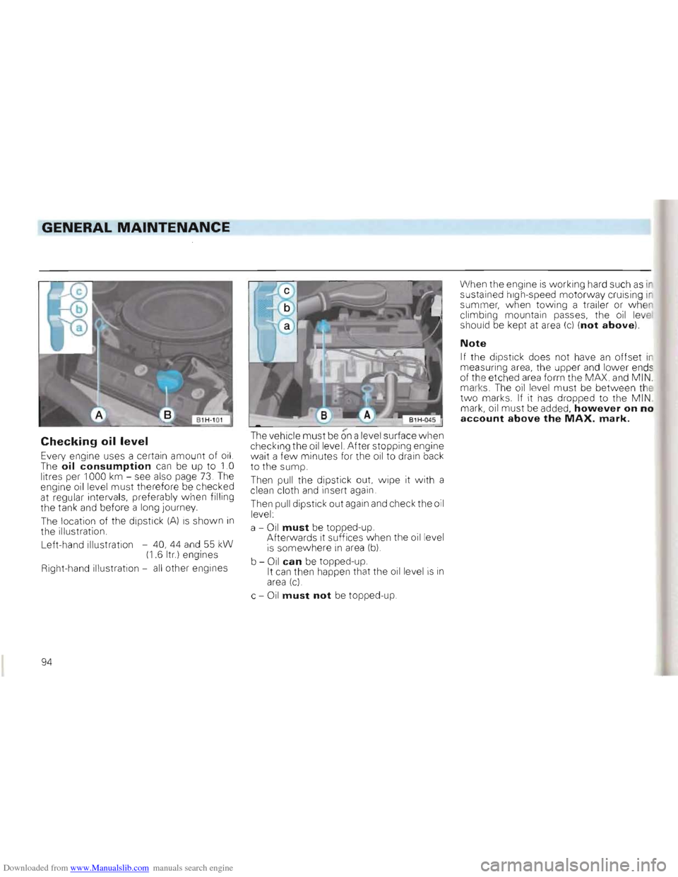
The locat ion of the dipst ick (A) IS shown in th e illustration.
Left-hand illustration -40 , 44 an d
55 kW (1 .6 Itr) en gi nes
Right-hand illustration -
all other engines
The ve hicle must be on a leve l surface when checking the oil level. A fter stopping engine
wa it a fe w minutes for the oil to drain back
to the sum p.
T hen pu ll the dipstick out, wipe it with a
clean cloth and insert again
Then pull dipstick out again
and check th e oi l
level :
a -
Oil must be topped-up.
Afterwards it suffices when the oil level
is somewhere in area (b)
b -Oil can be topped-up.
I t can then happen that the oil level is in area (c)
c -Oil must not be topped-up. When
the engine
is working hard such as ir
sustained high-speed motorway cruisin g in
summer, when towing a trailer or w he n
c limbing mountain passes , the o
il lev e! should be kept at area (c) (not above).
Note
If t he dipstick does not have an offset in
meas uring area, the upper and lower ends
of the etched area forrn the MAX. and MIN .
marks. The oil level must be between the two marks. If it has dropped to the M I N . mark, oil mu st be added, however on no account above the MAX. mark.
94
Page 115 of 156
Downloaded from www.Manualslib.com manuals search engine DO-lT-YOURSELF
Storage of vehicle tools, spare wheel and
ball coupling* of trailer bracket
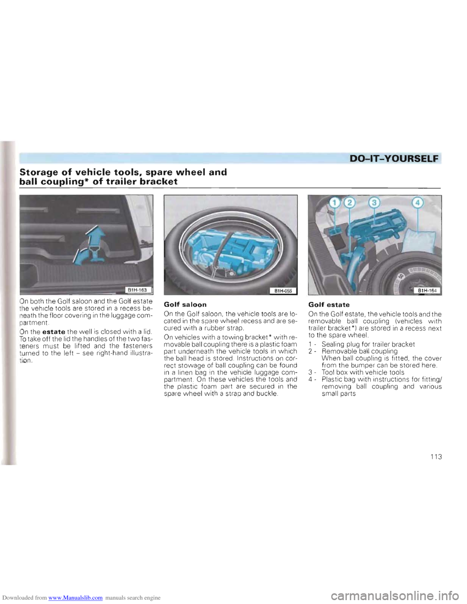
On both the Golf saloon and the Golf estate
t h e vehicle tools are stored in a rece ss be
n e ath the floor covering in the luggage com
p a rtment.
O n the
estate the w ell is closed with a lid. To take off the lid the handles of the two fas
t ener s must be lifted and the fasteners
t u rned to the left -see right-hand illustra
i
on.
Golf saloon
On the Golf saloon, the vehicle tools are lo
cated in the spare wheel recess and are se
cured with a rubber strap.
On vehicles with a to wing bracket* with removable ball coupling there is a plastic foam
part underneath the vehicle tools in w hich
the ball head is stored . Instructions on cor
rect stowage of ball coupling can be found in a linen bag in the vehicle luggage com
partment. On these vehicles the tools and the plastic foam part are secured in the
spare wheel with a stra p and buckle .
Golf estate
On the Golf estate, the vehicle tools and the
remo vable ball coupling (vehicles with trailer bracket*) are stored in a recess next
to the spare w heel.
1 - Sealing plug for trailer bracket
2 - Remo vable ball coupling
When ball coupling
is fitted , the cover
from the bumper can be stored here.
3 -Tool box with vehicle tools
4 - Plastic bag with instructions for fitting/
removing ball coupling and various
small parts
113
Page 122 of 156
Downloaded from www.Manualslib.com manuals search engine DO-lT-YOURSELF
Fuse layout
(from left to rig ht)
No. Component A 1)
1 Dipped beam left,
headlight range control left 10 2 Dipped beam right,
head light ra nge co ntrol right 10 3 Instrument and number plate
light ing . 10 4 Rear w iper, slid ing/tilti ng roo f, 15
5 Windscreen w ipe r, windscr een
a
nd rea r w indo w was her,
ele c. heated windsc reen washer
jets . . . . . . 15
6 Blower,
air co nditi oner ... . 30
7 Tail and side light ri ght 10
8 Tail and side light left . . 10
9 Rear window heating , mirror
heating ... 20 10 F og lights, rear fog light 15 11 Main beam left, main beam
w arnin g lamp 10
12 Mai n bea m right . 10
13 Horn, radiator fan (run- on) . 10
14 Reve
rsi ng lights, electric out
side mirrors, seat heating,
elec. w ind ows,
air conditio ne r
cruis e contro l system 15
No. Component Amp. 1)
15 Engine elec tronics , cool ant
c irculat ion run- on pump,
(six cylinder engine)
.. . .. .. . . . 10
16
Warning lamps, glove box light,
cas sette sto rage box light, 15
17 T urn sig nals. . . . . . . . . . . . .. 10 18 Electri c fue l pum p,
Lambda probe ..... .. ....... 20
1 9 Radiat or fan, air cond itioner. . 30
20 Brake lights, cruise control
syste m (tri gger conta cts
on brake and clutch pedals) . 10 21 Interior and luggage compart
ment lights, clock, cigarette lighter,
ce ntral
locking, multi -function
indicator 15 22 Radio 10
Automatic fuse
All electric windows are protected to
ge ther via an automatic fu se (see rig ht -hand
co lum n) which breaks the circuit when
overloaded (e .g. windows frozen) and makes the circuit again after a few seconds.
Additional fuses
(in separate holders)
• above the
rela ys:
Fu se for ABS motor re lay. ..... . .... 30
Fuse for ABS main relay. ... 30
Fuse for normal air conditioner 10
Fuse for fresh air blower on
Climatronic ... ... ... . 30
Fuse for C1imatronic .. .... ... 5
Automatic fuse for electric w indo ws .. 20
Trailer perma nent + 15
• in the engin e compa rtment on the bulk
head above the brake servo:
Diesel glow plugs 21 . . 50
Fuse colour code:
Light brown :
5 Amper e
Red: 10 Ampere Blue: 15 Ampere Yellow 20 Ampere Green 30 Ampere
21 This fuse shou ld onl y be renewed by a Volks wagen dea ler.
1) Amper e
120