ignition VOLKSWAGEN GOLF 2011 Owner´s Manual
[x] Cancel search | Manufacturer: VOLKSWAGEN, Model Year: 2011, Model line: GOLF, Model: VOLKSWAGEN GOLF 2011Pages: 138, PDF Size: 49.24 MB
Page 62 of 138
Downloaded from www.Manualslib.com manuals search engine f!l In cool or damp wea her, the mtenor of the
L!J headltgh s. rear lights and turn stgnals may
m1st up bm.:fly Thts 1s normal and does not affect
the serv•ce life of the hghts on your vehicle
l'('n First read and observo the Introductory
L-..kJ.J Information and safety warnings.&. on
page 105 .
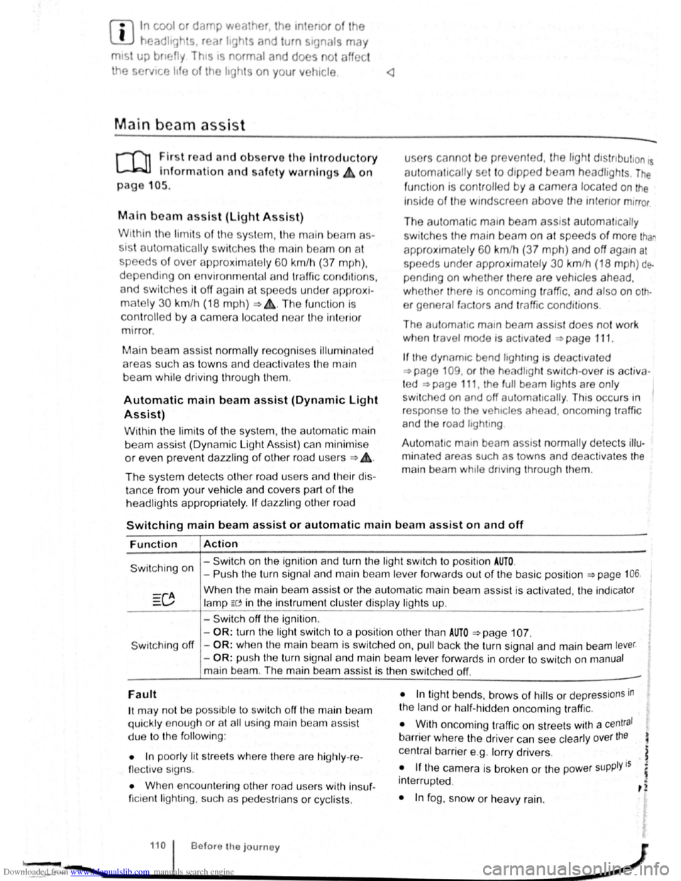
Main beam assist (Light Assist)
W•thtn the limit s of th e sy s te m , th e main b eam as
sis t au t
omatically swi tc h es the main bea m on at
speeds o f o ve r approxim ate ly 60 km/h (3 7 m ph) ,
depending on environm ent al a nd traffic condttions,
and swi tc hes it off again at spee ds und er appr oxi
mately 30 km /h (18 mph) ~&.The fun ction is
controlled by a came ra lo ca te d nea r the int erior
mirro r.
Main beam ass is t n ormall y recog nises illumin ate d
areas such as to wn s and deac tivates
the main
beam while driving throug h th em .
Automatic main beam assist (Dynamic Light
Assist)
W ithin the limits of the sys tem , the aut omatic main
beam assist (Dynamic Light A ssist) ca n minimi se
or even prevent dazzling of other road use rs ~ &.
The system detects other road users and their dis
tan ce from your vehic le and covers part o f th e
he adlights appropriately .
If dazz ling other road u
so rs canno t be
pre vented , th e ligh t dtstnbution rs
automa ticall y se t to d1pped beam headlights . The
func tion is controlled by a camera located on the
in side of th e wind screen above the mterior m~rror
The automatic m am beam assist automati cally
s w it c hes the main beam on at speeds
of more than
approximately 60 km /h (37 m ph) and off again at
speeds under approxima te ly 30 km /h (18 mph ) de
pending on whether there a re vehicles ahead.
wh eth er t here is oncoming traffic, and also on
oth
e r g eneral factors and traffic conditions .
Th e
automat1c main beam assist does no t work
w hen
travel mode is ac tt v ated ~page 111.
If the dynamt c bend llgh ttng is deac tivate d
~page 109 , or t he headltgh t switc h -ove r is acti va
t ed
~page 111, the f ull beam lights are only
s w it ched on and off automa ttcall y. This occurs i n
r esponse to
the v ehtcles ahead, oncoming traffic
a nd
the road lighting
Aut oma t
1c main beam assist normally dete cts illu
min ate d areas such as to wns and deac tiv a tes the
mai n beam wh ile dnving throug h them .
Switching main beam assist or automatic main beam assist on and off
Function Action
- Switch on the ignition and turn the light switch to positio n AUTO.
Switching on -Push the turn signal and main be am le ve r forwards out of the basic position ~page 106.
Wh en the m ain beam assis t or the au tom atic main beam assist is activ ated, the indica tor
la mp W in the instrument clu ste r display ligh ts up .
- Swi tc h off
the ignition .
-
OR : turn the light swit ch to a position other than AUTO ~page 107.
S wit ching off -OR : when the main bea m is swi tc h ed on, pull back the turn signal a nd main beam lever.
- OR : push the turn signa l and main beam le ver forwards in order to switch on manual
main bea m. The main beam assist is then switched off. -
Fault
1t may not be pos sibl e to switch off the main beam
qui ckly e nou gh or at all using main bea m assist
due to
the follo win g:
• In poo rly lit
str ee ts whe re the re are highly -re
flec tiv e sig ns.
• Wh en enco unt ering other road u sers with insuf
ficie nt lighting , su ch as p ed es trian s or cyc lis ts .
• In tigh t bends, brows of hills or dep ressions in
the land or h alf-h idde n oncomi ng traffic.
• W ith oncoming traff ic on str eets with a central
barrier where the driver can see clearly over the
central barrier e .g . lo rry drivers .
• If the came ra is broken or the pow er supply is
interrupt ed .
• In fog , sno w or hea vy rain.
... ~.==~~~~~~------1•1•0.i .. B .. ef•o •re .. th •e• j•o •u •rn•e•y._ .................. __________________ .............. ~ -.,
Page 64 of 138
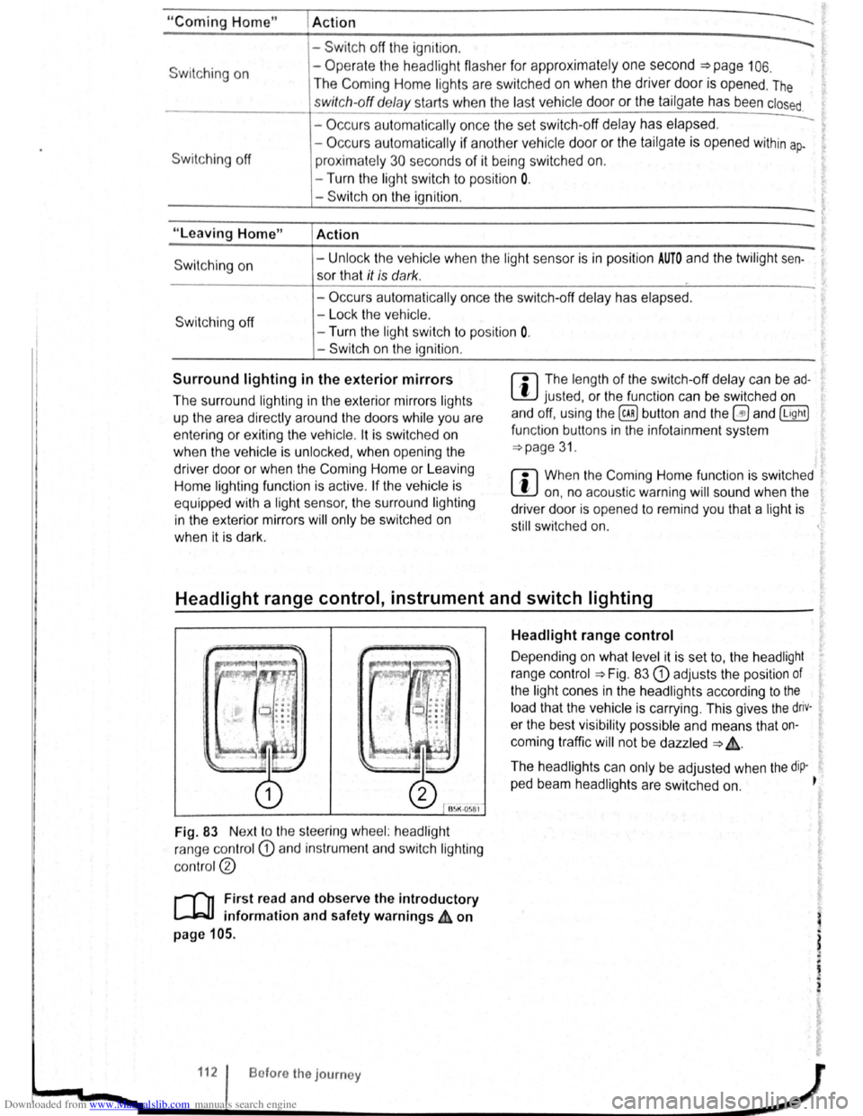
Downloaded from www.Manualslib.com manuals search engine "Coming Home"
Switching on
Switching off
"Leaving Home"
Switch ing on
Switc h ing off
I Action
------Swit c h off the ignit io n .
- Operate the headlight flashe r for approximately one second ~page 106.
The Coming Home lights are switched on when the driver door is opened . The
swi tc h-off de lay starts when the last vehicle door or the tailgate has been closed
-Occurs automatica lly once the set switch-off delay has elapsed .
-Occurs automatica lly if another ve h icle door or the tailgate is opened within ap-
proximately 30 seco nds of it being swit ched on.
- Turn the
ligh t switc h to positio n 0.
- Swit ch o n the ignition .
Action
-Unl ock the vehicle when the ligh t senso r is in position AUTO and the twilight sen
sor that it is d ar k.
- Occ urs autom atically once the switch-off delay has elapsed .
- Lo ck
the vehicle.
-Turn the light switc h to positi on 0.
-Switch on the ignition .
Surround lighting in the exterior mirrors m The length of the switch-off delay can be ad
L!:J justed , o r the function can be switched on
and off, u sing the
(ill) button and the~ and (Light)
functio n buttons in the infota inment system
=:.page 31.
Th e surround lighting in the exterior mirrors ligh ts
up the area directly around
the doors while you are
ente ring or ex iting the vehicle . lt is sw itc h ed on
when th e ve hi cle is unlo cked, when opening the
driver door or wh en
the Coming Home or Leav ing
Hom e lighting function is ac tiv e .
If the veh icle is
eq uipp ed with a ligh t sensor , the surround lighting
i n th e exterior mirrors
will only be switched on
wh en it is dark.
m When the Com ing Home function is switched .
L!:J on, no acoustic warning will sound when the t
driver d oor is opened to remind you that a light is
still switched on.
Headlight range control, instrument and switch lighting
Fig. 83 Nex t to the stee ring wheel: head light
ra nge contr ol
CD and in strum ent and swit ch lighting
co ntr ol@
r-('n First read and observe the introductory
~ information and safety warnings ~ on
page 105.
112 Bofore the journey
Headlight range control
D epending on what level it is se t to, the head light
rang e co ntrol
:::.Fig . 83 CD adjusts the position of
the light cones in the head lights according to the
load that the vehi cle is carrying. This gives the driv·
er the best visibilit y possible and means that on
coming traffic
will not be dazzle d :::. &.
The hea dlights ca n on ly be adjust ed when the dip-
ped beam headlights are switched on. ~
t
Page 65 of 138
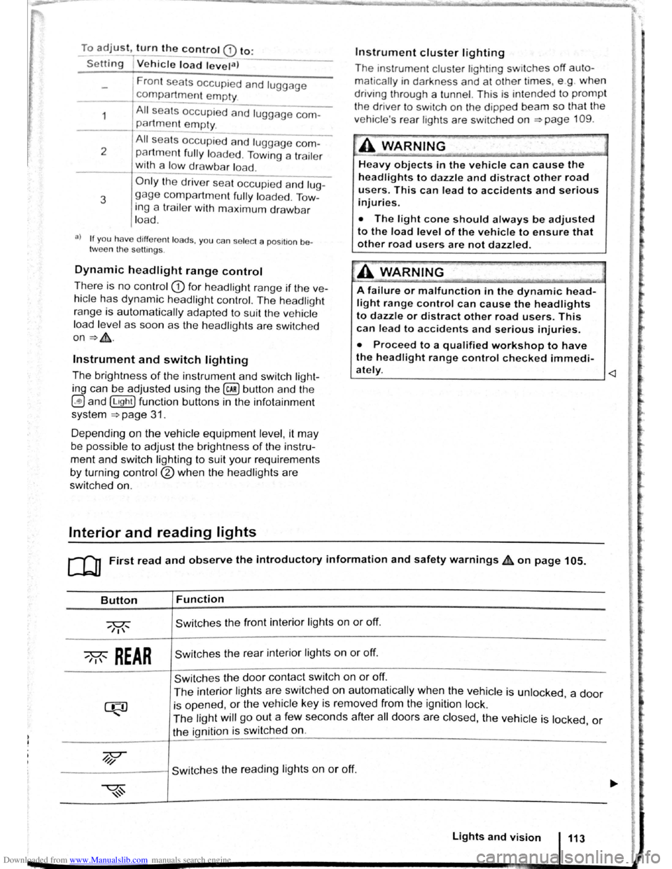
Downloaded from www.Manualslib.com manuals search engine To adjust, turn the control CD to:
-Set~ng I Vehicle load lev~la) -------
1
2
3
Fron t seats occupied and luggage
compa rtment
empty.
All seats occupied and luggage com
partment empty.
All sea ts occ upi ed and luggage com
partm ent fully loaded . Towing a trai le r
wit h a
lo w drawbar load .
Only the driver sea t occupi ed and lug
ga ge compartm ent fully load ed . Tow
ing a trai le r w ith maximum drawbar
l
oad.
a) If you have diff ere nt loads. you can select a positi on be
tween th e settings.
Dynamic headlight range control
Th ere is no control CD for headlight range if the ve
hicle
has dynamic headli ght control. The head light
r ange is
automatically adapted to suit the ve hicle
load level as soon as the headli ghts are switched
on~&.
Instrument and switch lighting
The brightness of the in strument and switch li gh t
ing can be adjusted using the @ill button and the
~and !Ltght] function buttons in the infot ainm ent
system
~page 31 .
Depending on the vehicle equipment level, it may
be possible to adjust the brightness of the instru
ment and switch lighting to suit your requirements
by turning control® when the headlights are
switched on.
Interior and reading lights
Instrument cluster lighting
The instrumen t cl uste r ligh ting sw it c hes off auto
mati cally
in darkness and at other times, e.g . when
driving through a tunnel. This is in tended to prompt
the driver to switch on the dipped beam so that the
v e hi cle' s rea r l
ights are swit c hed on ~page 109.
.A WARNING
-
Heavy objects in the vehicle can cause the
headlights to dazzle and distract other road
users. This can lead to accidents and serious
injuries.
• The light cone should always be adjusted
to the load level of the vehicle to ensure that
other road users are not dazzled.
A WARNING
A failure or malfunction in the dynamic head
light range control can cause the headlights
to dazzle or distract other road users. This
can lead to accidents and serious injuries.
• Proceed to a qualified workshop to have
the headlight range control checked immedi
I
ately. ~--------------- --------------------~
ClJ] First read and observe the introductory information and safety warnings & on page 105.
Button
~REAR
Function
Switches the front interior lights on or off.
Switches the rear interior lights on or off.
Switches the door contact switch on or off.
The interior lights are switche d on automatically when the vehicle is unlocked , a door
is opened, or the ve hicle key is removed from the ignition lock.
The light will go out a few seconds after all doors are closed, the vehicle is locked, or
the ignition is switched on.
/q'j/
---------j Switches the reading lights on or off.
Lights and vision 113
Page 68 of 138
Downloaded from www.Manualslib.com manuals search engine Windscreen wiper lever
@
c©
c@
C@
~®
B5K ~18
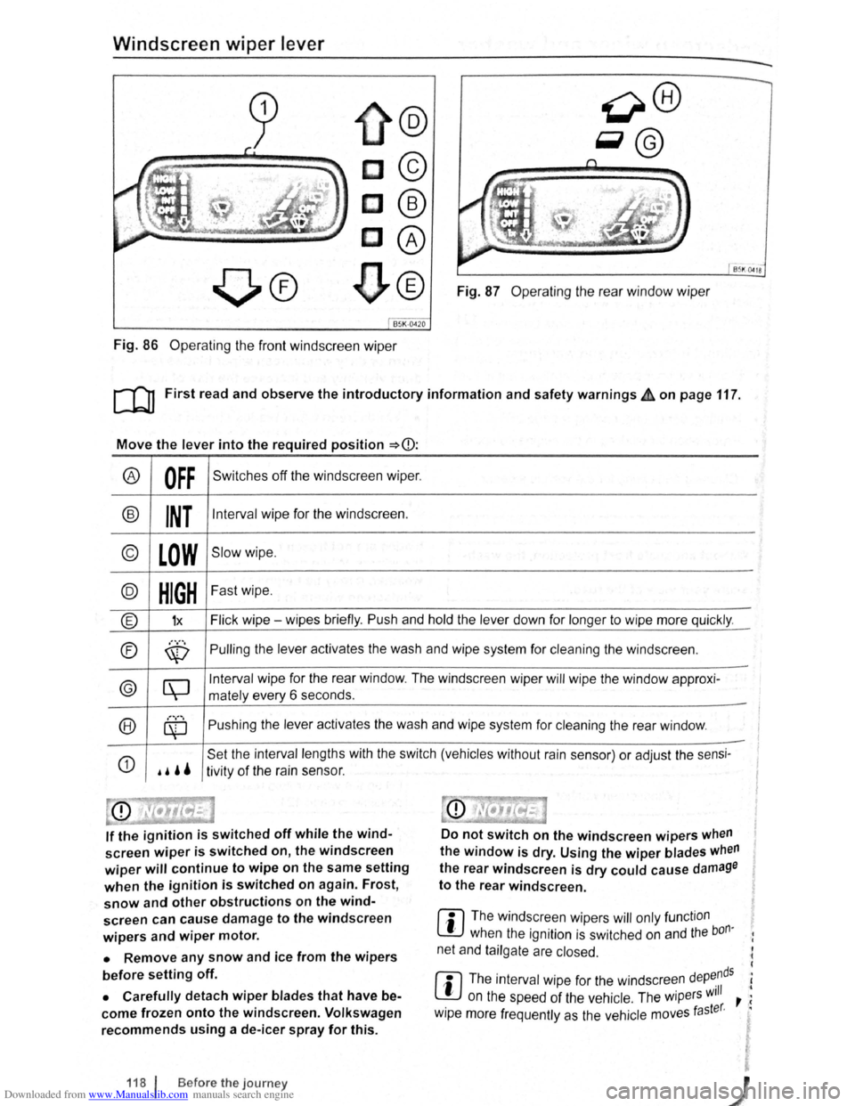
Fig. 87 Operating the rear window wiper
Fig. 86 Operating the front windscreen wiper
[Q] First read and observe the introductory information and safety warnings£ on page 117.
Move the lever into the required position ~CD:
® OFF Switches off the windscreen wiper.
® INT Interval wipe for the windscreen.
© LOW Slow wipe .
@ HIGH Fast wipe.
® 1x Flick wipe - wipes briefly. Push and hold the lever down for longer to wipe more quickly .
®
............. Pulling the lever activates the wash and wipe system for cleaning the windscreen . \V
© [\J
Interval wipe for the rear window. The windscreen wiper will wipe the window approxi-
mately every 6 seconds .
®
............
Pushing the lever activates the wash and wipe system for cleaning the rear window . ~ -
G)
.. ''
Set the interval lengths with the switch (vehicles without rain sensor) or adjust the sensi-
tivity of the rain sensor.
If the ignition is switched off while the wind
screen wiper is switched on, the windscreen
wiper will continue to wipe on the same setting
when the ignition is switched on again. Frost,
snow and other obstructions on the wind
screen can cause damage to the windscreen
wipers and wiper motor.
• Remove any snow and ice from the wipers
before setting off.
• Carefully detach wiper blades that have be
come frozen onto the windscreen. Volkswagen
recommends using a de-icer spray for this.
118 f Before the journey
Do not switch on the windscreen wipers when
the window is dry. Using the wiper blades when
the rear windscreen is dry could cause damage
to the rear windscreen .
r:l The windscreen wipers will only function
lJJ when the ignition is switched on and the bon·
net and tailgate are closed.
r:l The interval wipe for the windscreen depe.nds
l!:J on the speed of the vehicle . The wipers will , ;
· taster. · w1pe more frequently as the vehicle moves
i I
Page 70 of 138
Downloaded from www.Manualslib.com manuals search engine Place the windscreen wiper arms back onto the
winds creen before driving away. With the ignition
swit ched on, briefly press the windscreen wiper
lever
down to bring the windscreen wiper arms
ba ck
to the original position.
Lifting the windscreen wiper blades
• Move the wiper arms to the service position be
fore lifting ~CD.
• When lifting a wiper arm hold it only by the wip
er blade mounting .
Rain sensor
1}®
c®
85K ·0419
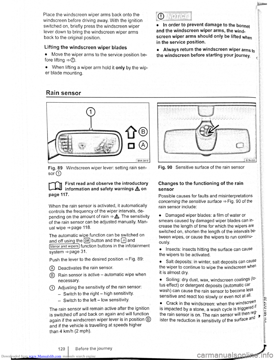
Fig. 89 Windscreen wiper lever: setting rain sen
sor G)
r-('n First read and observe the introductory
L-J,::JJ information and safety warnings & on
page
117.
When the rain sensor is activated , it automatically
controls the frequency
of the wiper intervals, de
pending on the amount of rain ~ ,&. The sensitivity
of the rain sensor can be adjusted manually. Man
ual
wipe ~page 118 .
The automatic wipe function can be switched on
and off using the
(ill) button and the 0 and
[Mirror and wipers ] function buttons in the infotainment
system
~page 31.
Push the lever to the desired position ~Fig. 89:
® Deactivat es the rain sensor.
@ Rain sensor is active -automatic wipe when
necessary .
G) Adjusting the sensitivity of the rain sensor :
-
Switch to the right -high sensitivity.
-
Switch to the left -low sensitivity .
The rain sensor
will remain active after the ignition
is switched off and back on again and
will function
again
if the windscreen wiper lever is in position @
and if the vehicle is travelling at speeds higher
than 4 km/h
(2 mph).
• In order to prevent damage to the bonnet
and the windscreen
wiper arms, the wind
screen wiper arms should only be lifted when
in the service position.
• Always return the windscreen wiper arms to
the windscreen before starting your journey.
Fig. 90 Sensitive surface of the rain sensor
Changes to the functioning of the rain
sensor
Possible causes for faults and misinterpretations
concerning the sensitive surface~ Fig. 90 of the
rain sensor include:
• Damaged wiper blades: a film of water or
smears caused by damaged wiper blades
can in
crease the length of time for which the wipers are
switched on, shorten the length of the intervals be
tween wipes, or cause the wipers to run continu
ously.
• Insects: insects hitting the surface can cause
the wipers to be activated.
• Salt deposits : in winter, salt deposits can cause
the wiper to continue to wipe the windscreen when
it is almost dry.
• Soiling : dry dust, wax, windscreen coatings (lo·
tus effect) or detergent deposits (automatic car
wash) can cause the rain sensor to become less
sensitive and react too slowly or even not at all.
• Crack
in the windscreen : when the windscree~
is impacted by a stone, a wash cycle is triggered If ....
~he rain sensor is on . The rain sensor will then reg-,. ~
1ster the reduction in sensitivity of the surface and ~
120 I Before the journey _,}
~----~------------------~~
Page 74 of 138
Downloaded from www.Manualslib.com manuals search engine sockets in the vehicle
....
-c, r-, o o o o o CJ 0 o
I
(_; 0 () () () (j () (J f')
® l
0 (J (_) () () f') 0 0 u 0 c) ( J (j 0 ( j () 0 0 (J 0 () f) u f) f) 0 () (; 0 000(;00000 ) 0 0 0 (J 0 0 0 0 0 0
-............ .--. --'
--J.> ,, B~K-0578
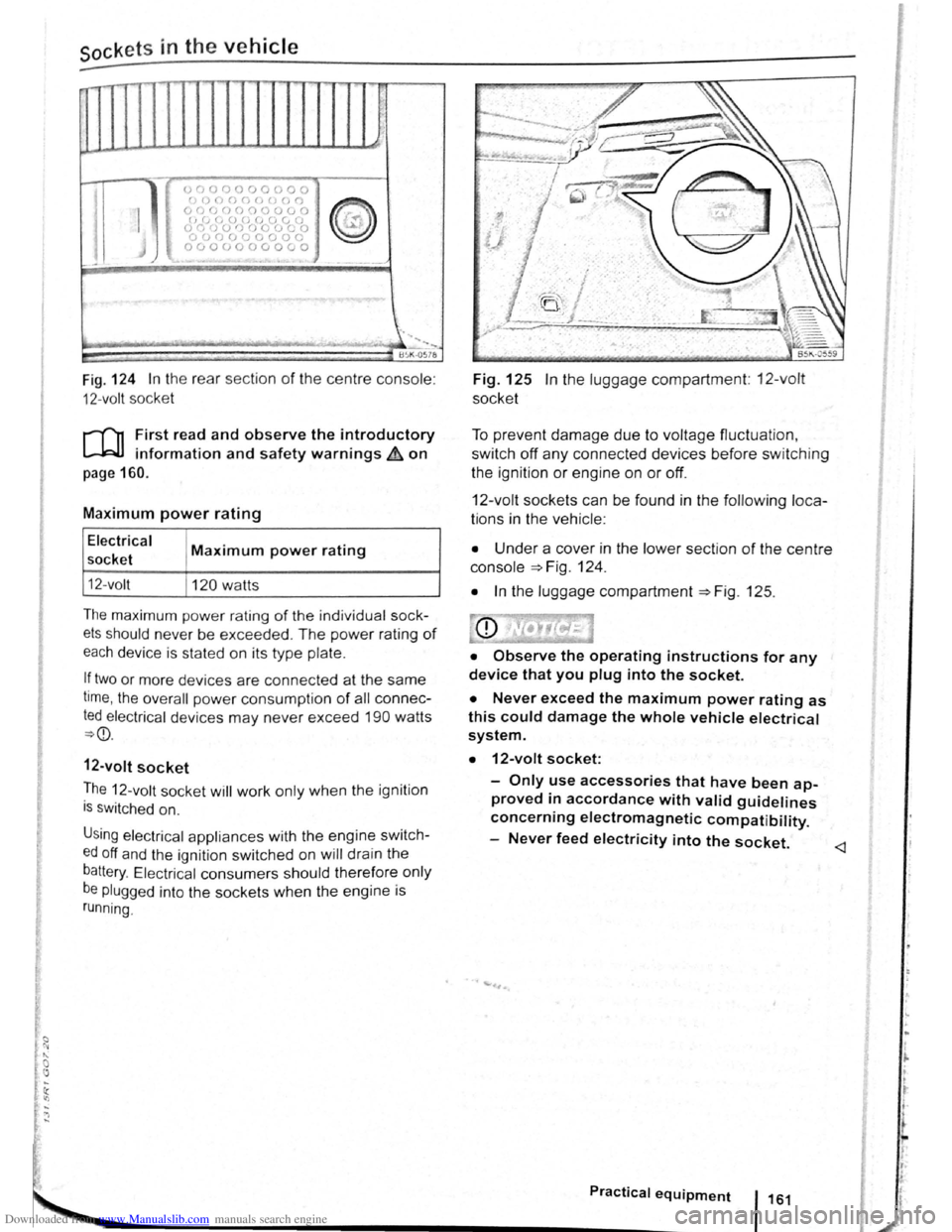
Fig . 124 In the rear sect ion of the centre console :
12-volt socket
l'('n First read and observe the introductory
l-bJ.J information and safety warnings&. on
page 160.
Maximum power rating
Electrical
socket
12- volt
Maximum power rating
120 watts
The maxim um power rating of the individ ua l sock
ets should never be exceeded . The power rating of
each device is stated on its type plate.
If two or more devices are connected at the same
time, the overall power consump tion of all con nec
ted electrical devices may never exceed 190 watts
~CD.
12-volt socket
The 12-volt socket will work only when the ignition
is switc hed on.
Using elec tric al app liances with the engine swit ch
ed off and the ignition switched on will drain the
battery. Electrical consumers should therefore only
be plugged into the sockets when the engine is
running.
Fig. 125 In the luggage compartment: 12-volt
socket
To prevent damage due to voltage fluctuation ,
switch
oft any connected devices before switching
the ignition
or engine on or off.
12-volt socket s can be found in the following loca
tions in the vehicle :
• Under a cover in the lower section of the centre
console =>Fig. 124 .
• In the luggage compartment =>Fig. 125.
• Observe the operating instructions for any
device that you plug into the socket.
• Never exceed the maximum power rating as
this could damage the whole vehicle electrical
system.
• 12-volt socket:
-Only use accessories that have been ap
proved in accordance with valid guidelines
concerning electromagnetic compatibility.
-
Never feed electricity into the socket.
Practical equipment 1161
Page 75 of 138
Downloaded from www.Manualslib.com manuals search engine CD
Please note the following to help avoid damag o
and premature wear:
• Do not rest your hand on the g ear le ve r
when
driving. The pressure from your hand is
passed onto the selector forks in the gearbox.
Automatic gearbox: selecting a gear
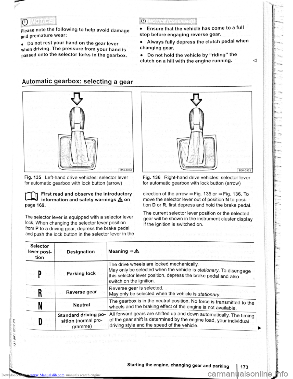
Fig . 135 Left-hand drive vehicles : selector lever
for automatic gearbox with lock button (arrow)
r-('n First read and observe the introductory
~ information and safety warnings & on
page 169.
The selector lever is equipped with a selector lever
lock .
When changing the selector lever position
from P to a driving gear, depress the brake pedal
and push the lock button in the selector lever in the
Selector
lever posi-Designation Meaning ~ .&.
tion
stop bofore engaging re verse gear.
• Always fully d epress the clutch pedal when
changing gear.
• Do not hold the vehicle by "riding" the
clutch on a hill with the engine running.
Fig. 136 Right-hand drive vehicles : selector lever
for automatic gearbox with lock button (arrow)
direction
of the arrow ~Fig. 135 or ~Fig. 136. To
move the selector
lever out of position N to posi
tion D
or R, first depress and hold the brake pedal.
The current selector lever position or the selected
gear
will be shown in the instrument cluster display
if the ignition is switched on.
The drive wheels are locked mechanically .
p Parking lock May only be selected ~hen the vehicle is stationary. To disengage
this selector lever pos1t1on, depress the brake pedal and also
switch on the ignition .
R Reverse gear Reverse gear is selected.
May only be selected when the vehicle is
stationary.
N Neutral The gearbox is in the neutral position . No force is transmitted to the
wheels and the braking effect
of the engine is not available .
Standard driving po-All forward ge~r~ are shift~d up and down automatically . The timing
D sition (normal pro-of the gear sh1ft 1s determmed by the engine load, your individual
gramme) driving
style and the speed
of the vehicle . -
Starting the engine, changing gear and parking 173
Page 79 of 138
Downloaded from www.Manualslib.com manuals search engine • Please note that the driven wheels can
\start to spin and the vehicle can skid If the
lCS i w1tched off, especially If the road Is
slippery.
•
Switch the TCS back on after acceleration.
attempt to stop it from rolling back by depress·
lng the accelerator while a position is still se
lected. The automatic gearbox could overheat
and be damage d .
• Never allow the vehicle to roll In posi tion N ,
particularly If the Ignition is s w itched off. The
automatic gearbox w ill not be lubricated and
could be damaged .
r-'('n F irst read and observe the introductory
L-Wl Information and safety warnings .&. on
page 169 .
Emergency programme
There is a fault in the system if all the displays on
the mstrument clu ste r for the se lector le ve r posi
tions have a light background. The automatic gear
box is running in an emergency programme. The
vehicle can still be driven in the eme rg ency pro
gramme, but only at reduced speed and not in all
gear s.
In vehicles with a dual clutch gearbox DSG®, y o u
may
no longer be able to select reverse gear.
In all cases the automatic gearbox should be
checke d
by a qualified workshop immediately.
Overheating of the dual clutch gearbox
DSG®
The dual clutch gearbox can overheat when th e
vehicle pulls off re
gularly, travels at a crawl for long
penods, or in s
top and go traffic . Gearbox over- .
heating
is i ndi cate d by the w arning lamp 0 and tn
some cases by a text m essage in the instrument
cluste r d1splay . An acoustic warni ng may also be
heard . Stop the ve hi cle and allow th e gea rbox to
cool down
~CD.
The vehicle will not move forwards or
backwards even though a gear has been
selected
If the veh1cle w11l not move in the requi red direc
tio n, the system may have selected the pos1tion m
correctly Depress the bra e pedal and reselect the
pOSitiOn
If th e vehicle st1ll does not move tn the requ1red di
re ction , th ere IS a system fault. Seek expert assis
tance and have the system checked
• If the display indicates that the gearbox is
overheating for the first time, the vehicle will
have to be parked safely or driven faster than
20 km/h (12 mph) .
• If the text message and acoustic warning
are repeated approximately every 10 seconds,
the vehicle must be parked safely immediately
and the engine switched off. Allow the gearbox
to cool down.
•
In order to prevent damage to the gearbox,
you should not drive on unti l the acousti c
warning stops. You should not pull away or
drive the vehicle at very low speeds while the
gearbox is overheated.
' 177
~
l
I
i
t
Page 81 of 138
Downloaded from www.Manualslib.com manuals search engine • o;;--"cc A WAR'I'G (Contmued)
tf the brake warning lamp 0 does not go
'Jt or if it lights up when driving, the brake Ol , . • fluid level in the reservoir IS too low or there
is a fault in the brake system. Stop the vehi
c le immediately and seek expert assistance
=>page 188 , Brake fluid.
, tf the brake warning lamp ID lights up to
gether with the ABS indicator lamp 8, the
control function of the ABS may have failed.
This can cause the rear wheels to lock quick
ly when you brake. Locked rear wheels can
lead to a loss of control of the vehicle. If pos
s ible, reduce your speed and drive carefully
at low speed to the nearest qualified work
shop in order to have the brake system tes
ted . Avoid sudden braking and driving ma
noeuvres on the way.
• The ABS is not functioning correctly if the
ABS indicator lamp Et does not go out or
com es on while the vehicle is in motion. The
Electronic parking brake
BSIV)•~9
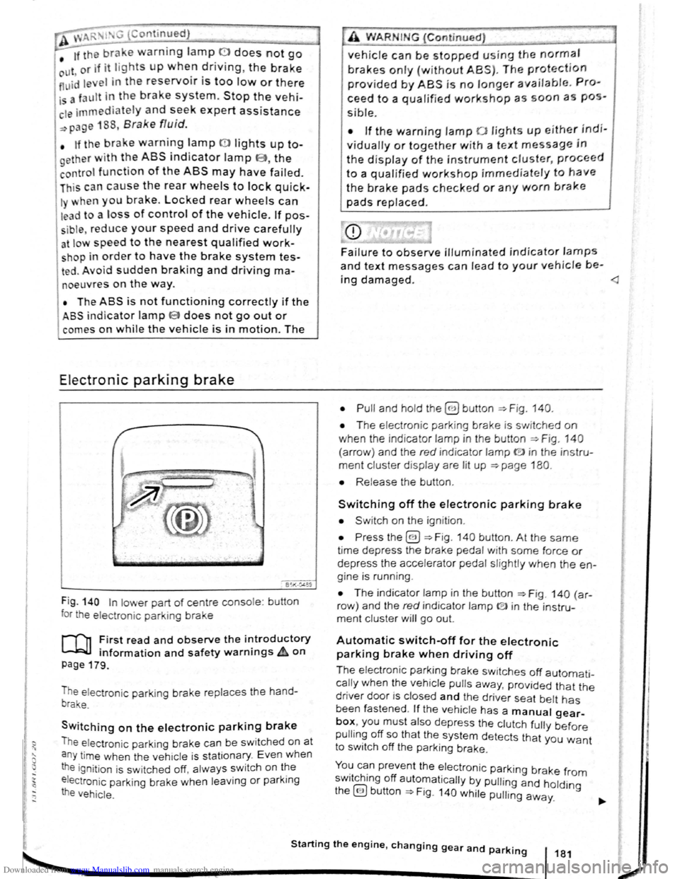
Fig . 140 In lower part of centre console : bu tton
for the electron ic parkin g brake
rf'n First read and observe the i~troductory
~ information and safety warnmgs A on
page 179.
The electronic parking brake replaces the hand
brake.
Switching on the electronic parking brake
The elec tron ic park ing brake can be swit ched on at
a n y time when the vehic le
is stationary . Even when
the ignition is sw itched off, always switch on the
e lectroni c parking brake when leaving
or parking
the vehicle .
_,
A WARN IN.G (Continued) .,~ ,1
vehicle can be stopped using the normal
brakes only {without ABS). The protection
provided by ABS is no longer available. Pro
ceed to a qualified workshop as soon a s pos
s ible.
• If the warning lamp 0 lights up either indi
vidually or together with a text message in
the d isplay of the instrument cluster, proceed
to a qualified workshop immediately to have
the brake pads checked or any worn brake
pads replaced.
Fa i
lure to observe illuminated indicator lamps
and text messages can lead to your vehicle be-
ing damaged.
• T he electron ic park ing brake is switched on
when the indicato r lamp in the button ::;;. Fig. 140
(a rro w) and the red indicator lamp ID in the instru
ment cluster displ ay are lit up ::;;. page 180.
• Release the button .
Switching off the electronic parking brake
• Swit ch on the ignition .
• Press the@) ::;;. Fig . 140 button . At the same
time depress the brake pedal with some force or
depress the accele rator pedal slightly when the en
gine is run ning .
• The indicator lamp in the button =:;.Fig . 140 (a r
row ) and the red indicator lamp ® in the instru
ment cluster will go out.
Automatic switch-off for the electronic
parking brake when driving off
The elec tronic parking brake switches off automati
cally when the vehi cle pulls away, prov ided that the
driver door is closed and the drive r sea t belt has
been fastened . If the vehicle has a manual gear
box, you must also depress the clutch fully before
pulling off so that the system detects that you want
to switch off the parking brake.
You can prevent the electronic parking brake f 0 . h. ff r m sw1tc 1ng o automat ically by pulling and hold.
the@) button::;;. Fig. 140 while pulling away. lng
Starting the engine, changing gear and parking 181
2
Page 87 of 138
Downloaded from www.Manualslib.com manuals search engine CD
• The ultrasound sensors should only be
sprayed briefly when cleaning with pressure
hoses and steam cleaners. A distance
of more
than
10 cm between the ultrasound sensors
and the steam/hose nozzle must
be observed.
• Sources of noise can lead to errors in the
ParkPilot system, e.g. rough asphalt, cobble
stones, induction loops, building equipment,
or
interference from other vehicles.
• Any equipment that has been retrofitted to
the vehicle, e.g . bicycle carriers, can prevent
the ParkPilot from functioning properly.
Operating ParkPilot
If an ultrasound sensor fails, the corrrespond.
ing area of the ultrasound sensor cluster is
switched off and cannot be reactivated until th
fault has been rectified. Consult a qualified
workshop in the event
of a system fault. Volks.
wagen recommends using a Volkswagen deal.
ership for this purpose .
r::l Volkswagen recommends that drivers prac
L!J tise using the ParkPilot in a traffic-calmed
area or car park to allow them to familiarise them
selves with the system and its functions.
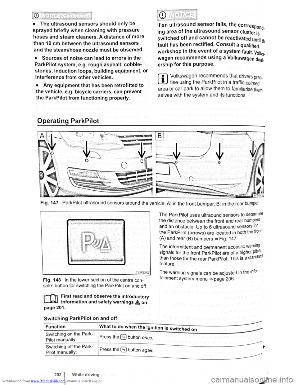
Fig. 147 ParkPilot ultrasound sensors around the vehicle, A: in the front bumper , B : in the rear bumper
BTT.Q530
Fig. 148 In the lower section of the centre con
sole: button for switching the ParkPilot on and off
r-('n First read and observe the introductory
l.-JRlJ information and safety warnings ,£ on
page 201.
Switching ParkPilot on and off
The ParkPilot uses ultraound sensors to determine
the distance between the front and rear bumpers
and an obstacle. Up to 6 ultrasound sensors for
the ParkPilot (arrows) are located in both the front
(A) and rear (B) bumpers :::.Fig. 147.
The intermittent and permanent acoustic
warn~ng
signals for the front ParkPilot are of a higher pitch d
than those for the rear ParkPilot. This
is a standar
feature.
The warning signals can be adjusted
in the info
tainment system menu :::.page 206.
Function What to do when the ignition is switched on
Switching on the Park
Pilot manually :
Switching off the Park
Pilot manually :
202 l While driving
Press the ~ button once.
Press the 5) button again.
,